0298 ailb titel.411 07.03.2005 13:37 uhr seite 2 amphenol ... · gehäusegröße-polbild / shell...
TRANSCRIPT
VG 95234Amphenol
GCB-BGCA-B
0298_ailb_titel.411 07.03.2005 13:37 Uhr Seite 2
1Inhaltsverzeichnis
Wir sind bestrebt, unsere Produkte weiter zu entwickeln undbehalten uns maßliche und technische Änderungen an denSteckverbindern vor.
Our products are the subject of continuous development andwe reserve the right to introduce changes in their design.
Ce document n’est pas contractuel. Les informationscontenues dans ce catalogue sont susceptible d’évolution.
Allgemeine Beschreibung / General description / Description générale 2
Elektrische Eigenschaften / Electrical properties / Propriétés électriques 3
Mechanische Eigenschaften / Mechanical properties / Propriétés mécaniques 4
Bestellschlüssel / How to order / Système de référence 5 – 7
VG95234 / GCB-B – Polbilder / Contact arrangements / Arrangements 8 – 13
Einbaumaße / Mounting dimensions / Cotes d’encombrement 13 – 14
Gehäuseformen / Shell style / Style de boîtier 15
VG95234 Form A / VG95234 Style A • VG95234 Form B1, B2 / VG95234 Style B1, B2 16
VG95234 Form D / VG95234 Style D • VG95234 Form E, E1 / VG95234 Style E, E1 17
VG95234 Form F / VG95234 Style F • VG95234 Form G / VG95234 Style G 18
VG95234 Form H / VG95234 Style H • VG95234 Form J1, J2 / VG95234 Style J1, J2 19
VG95234 Form K / VG95234 Style K • VG95234 Form L / VG95234 Style L 20
VG95234 Form M / VG95234 Style M • VG95234 Form N1, N2 / VG95234 Style N1, N2 21
VG95234 Form R1 / VG95234 Style R1 • VG95234 Form S1, S2 / VG95234 Style S1, S2 22
VG95234 Form T / VG95234 Style T • VG95234 Form U1, U2 / VG95234 Style U1, U2 23
VG95234 Form KR, KA / VG95234 Style KR, KA • VG95234 Form KB, KC / VG95234 Style KB, KC 24
VG95234 Blinddosen / VG95234 Dummies / VG95234 Support de serrageVG95234 Klemme / VG95234 Clamp / VG95234 Porte brides 25
VG95234 Knickschutztüllen / VG95234 Bushings / VG95234 ManchonsVG95234 Blindstopfen / VG95234 Sealing plug / VG95234 Obturateurs 26
VG95234 Dichtungen / VG95234 Gaskets / VG95234 Joints d’embase 27
GCB-B 3100 PG – PM / GCA-B 3100 PG – PM • GCB-B 3101 PG – PM / GCA-B 3101 PG – PM 28
GCB-B 3106 PG – PM / GCA-B 3106 PG – PM • GCB-B 3107 / GCA-B 3107 29
VG95234 / GCB-B – Stiftkontakte / Pin contacts / Contacts mâles 30
VG95234 / GCB-B – Buchsenkontakte / Socket contacts / Contacts femelles 31
VG95234 / GCB-B – Kontakte / Contacts / Contacts • VG95234 / GCB-B – Werkzeuge / Tools / Outillages 32
GCA-B – Polbilder / Contact arrangements / Arrangements 33 – 50
GCA-B – Werkzeuge / Tools / Outillages 50
GCA-B – Stiftkontakte / Pin contacts / Contacts mâles 51
GCA-B – Buchsenkontakte / Socket contacts / Contacts femelles 52
0298_ailb_kat.neu.411 04.03.2005 14:21 Uhr Seite 1
2 Allgemeine Beschreibung / General description / Description générale
GCB-B BaureiheDie Steckverbinder der GCB-B Baureihe mit Reverse-Bajonett-Verschluss entsprechen der Norm VG95234.Sie bieten eine hohe Zuverlässigkeit, sind wasserdicht, verschleiß- und vibrationsfest.Sie haben die gleichen Befestigungsmaße und Polanordnungen wie Steckverbinder nach MIL-C-5015, sind jedoch mitReverse-Bajonett-Verriegelung und Wellfeder versehen, was schnelles, müheloses Ver- und Entriegeln garantiert und bei starker Vibration einen großen Schutz gegen ungewolltes Entriegeln bietet.
Die nach VG95234 zugelassenen Bauformen sind grundsätzlich mit Einzeladerabdichtung ausgerüstet.Werden bei Steckverbindern nach VG95234 Modifikationen gewünscht, wie z.B. andere Oberflächenbehandlung, Kontaktausführungen oder Endgehäuse, so haben diese grundsätzlich eine GCB-B Bezeichnung.
Typische Anwendungen für diese Baureihen sind Wehrtechnik, industrielle Anlagen und Schienenfahrzeuge, sowie Antriebstechnik, Werkzeugmaschinen, Messtechnik und Robotik.
GCA-B BaureiheDie GCA-B Steckverbinder sind 100% austauschbar- und steckkompatibel mit den Steckverbindern der GCB-B Serieund bieten eine große Auswahl zusätzlicher Polbilder, die nicht in der VG95234 beschrieben sind.Sie besitzen den gleichen technischen Aufbau wie die GCB-B Serie, bis auf die Kontakte, welche ein anderes Design haben.
GCB-B SeriesThese connectors with reverse bayonet coupling are conform to the VG95234 standard.Offering a high liability, they are coevally waterproof and resistant to vibrations and wear.They use the same installation dimensions and contact arrangements as connectors according to MIL-C-5015. However theyare provided with reverse bayonet coupling and ondular washer, which guarantee a fast and effortless locking/unlocking andavoid an unintentional unlatch due to heavy vibrations.
All VG95234 designs are basically equipped with an individual wire sealing grommet.If VG95234 connectors are required with modifications, e.g. with solder contacts or other shell- or contact plating, they have tobe ordered with GCB-B designation.
Common applications include military sector, industrial plants and railway vehicles as well as propulsion technologies,machine tools, measurement and robotics.
GCA-B SeriesThe GCA-B connectors are fully interchangeable and intermateable with GCB-B connectors and offer a variety of additionalarrangements not described in the VG95234.They have the same technical setup as GCB-B series except the contacts that have a special design.
Gamme GCB-B Ces connecteurs à accouplement « Reverse Bayonet » répondent à la norme VG95234.Ils présentent une bonne résistance à l´usure, sont étanches et ont une très bonne tenue aux vibrations.Ils ont les mêmes dimensions de fixation et les mêmes arrangements que les connecteurs conformes à la norme MIL-C-5015.Ils possèdent un système d’accouplement « Reverse Bayonet » incluant une bague ondulée qui garanti un verrouillage /déverrouillage rapide et empêche, lors de vibrations importantes, un désaccouplement intempestif.
Tous les connecteurs VG95234 possèdent un grommet assurant l´étanchéité des conducteurs.Si des modifications sont requises sur les connecteurs VG95234 (traitement de surface, type de contacts, raccord arrière,etc…), ils ne seront livrables que sous la désignation GCB-B.
Les domaines d´utilisation de ces gammes sont le militaire, l’industriel, le ferroviaire, les machines-outils et la robotique.
Gamme GCA-BLes connecteurs GCA-B sont à 100% interchangeables et intermariables avec les connecteurs GCB-B et offrent ungrand nombre d’arrangements supplémentaires non décrits dans la norme VG95234.Ces connecteurs ont les mêmes caractéristiques techniques que la gamme GCB-B, à l’exception des contacts qui ont undesign spécifique.
0298_ailb_kat.neu.411 04.03.2005 14:21 Uhr Seite 2
3Elektrische Eigenschaften / Electrical properties / Propriétés électriques
Nennstrom bei 20°C / Nominal current at 20°C /Courant nominal à 20°C
Kontaktgröße /Contact size /
Taille de contact
Max. Nennstrom /Max. nominal current /Courant nominal maxi
(A)
10 8
15S / 16S 22
15 / 16 22
25 / 12 41
60 / 100 / 8 74
160 / 4 135
500 / 0 245
Betriebsstrom / Rated current / Courant d’utilisation
In Abhängigkeit von der Umgebungstemperatur / Dependingon ambient temperature / En fonction de la température ambiante
Isolationswiderstand / Insulation resistance / Résistance d’isolement
≥ 1000 MΩ
Température Contact 15 Contact 25 Contact 60 Contact 16020 8 22 41 73 135 224530 7,5 21 39 70 130 223240 7,3 20 37 66 123 221850 7 19 35 62 115 220260 6,7 18 32 58 108 18870 6,4 17 30 53 98 17080 6 16 27 47 88 15390 5,6 15 23 40 75 132100 5 13 19 32 60 110110 4 10 14 22 42 80115 3 8 11 17 30 60120 2 5 7 10 18 32125 0 0 0 0 0 0
0
10
20
30
40
50
60
70
80
90
100
110
120
130
140
150
160
170
180
190
200
210
220
230
240
250
20 40 60 80 100 120(°C)
(A)
500/0
25/12
60/100/8
15S/16S/15/16
160/4
10
500/0
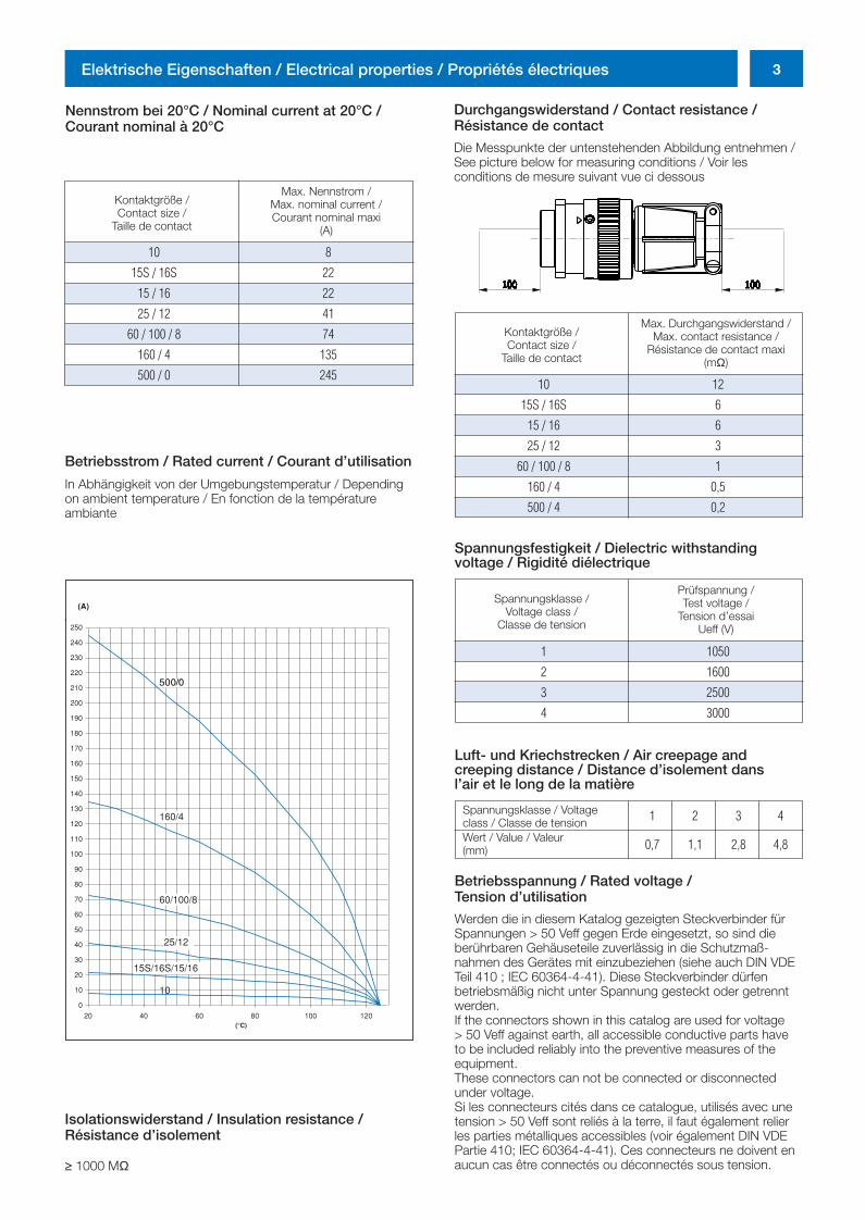
Durchgangswiderstand / Contact resistance / Résistance de contact
Die Messpunkte der untenstehenden Abbildung entnehmen /See picture below for measuring conditions / Voir les conditions de mesure suivant vue ci dessous
Kontaktgröße /Contact size /
Taille de contact
Max. Durchgangswiderstand /Max. contact resistance /
Résistance de contact maxi(mΩ)
10 12
15S / 16S 6
15 / 16 6
25 / 12 3
60 / 100 / 8 1
160 / 4 0,5
500 / 4 0,2
Spannungsfestigkeit / Dielectric withstanding voltage / Rigidité diélectrique
Spannungsklasse /Voltage class /
Classe de tension
Prüfspannung /Test voltage /
Tension d’essaiUeff (V)
1 1050
2 1600
3 2500
4 3000
Luft- und Kriechstrecken / Air creepage andcreeping distance / Distance d’isolement dans l’air et le long de la matière
Spannungsklasse / Voltageclass / Classe de tensionWert / Value / Valeur(mm)
1 2 3 4
0,7 1,1 2,8 4,8
Betriebsspannung / Rated voltage / Tension d’utilisation
Werden die in diesem Katalog gezeigten Steckverbinder fürSpannungen > 50 Veff gegen Erde eingesetzt, so sind dieberührbaren Gehäuseteile zuverlässig in die Schutzmaß-nahmen des Gerätes mit einzubeziehen (siehe auch DIN VDETeil 410 ; IEC 60364-4-41). Diese Steckverbinder dürfenbetriebsmäßig nicht unter Spannung gesteckt oder getrenntwerden.If the connectors shown in this catalog are used for voltage > 50 Veff against earth, all accessible conductive parts have to be included reliably into the preventive measures of the equipment.These connectors can not be connected or disconnectedunder voltage. Si les connecteurs cités dans ce catalogue, utilisés avec unetension > 50 Veff sont reliés à la terre, il faut également relierles parties métalliques accessibles (voir également DIN VDEPartie 410; IEC 60364-4-41). Ces connecteurs ne doivent enaucun cas être connectés ou déconnectés sous tension.
0298_ailb_kat.neu.411 04.03.2005 14:21 Uhr Seite 3
4 Mechanische Eigenschaften / Mechanical properties / Propriétés mécaniques
Umgebungstemperatur / Operating temperature /Température d’utilisation-55 / 125°C
Steckzyklen / Cycles / Endurance
500 min.
Schutzart / IP code / Indice de protection
Alle Endgehäuse mit Grommet erfüllen IP67 (bei Einzeladernnur in vollbestücktem Zustand). Bei Steckern mit PG- odermetrischem Endgehäuse ist die Schutzart von der Schutzartdes Adapters abhängig.All backshells with grommet are IP 67 (only if all cavities areused). For connectors with PG- or metrical backshell, the IPcode depends on the IP code of the adapter which will beused.Tous les raccords avec grommet sont IP 67 (uniquement sitoutes les cavités sont obturées). Pour les connecteurs avecraccord PG- ou métrique, le degré d’étanchéité dépend decelui du serre câble utilisé.
Schwingung / Vibration / Vibration
200 m/s2 bei 10 bis 2000 Hz200 m/s2 at 10 to 2000 Hz200 m/s2 pour 10 à 2000 Hz
Kontakthalterung / Contact retention / Rétention des contacts
Kontaktgröße /Contact size /
Taille de contact
Prüfkraft / Test force /Force de test
(N)
10 30
15S / 16S 35
15 / 16 35
25 / 12 55
60 / 100 / 8 80
160 / 4 90
500 / 0 95
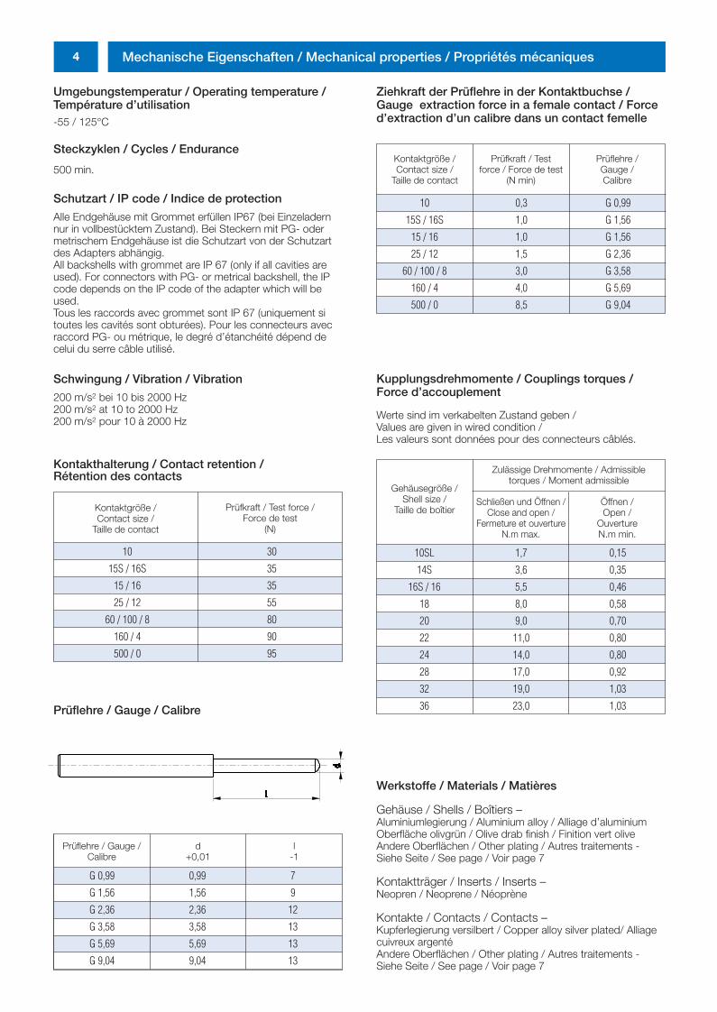
Prüflehre / Gauge /Calibre
d+0,01
l-1
G 0,99 0,99 7
G 1,56 1,56 9
G 2,36 2,36 12
G 3,58 3,58 13
G 5,69 5,69 13
G 9,04 9,04 13
Prüflehre / Gauge / Calibre
Ziehkraft der Prüflehre in der Kontaktbuchse /Gauge extraction force in a female contact / Forced’extraction d’un calibre dans un contact femelle
Kontaktgröße /Contact size /
Taille de contact
Prüfkraft / Testforce / Force de test
(N min)
Prüflehre / Gauge / Calibre
10 0,3 G 0,99
15S / 16S 1,0 G 1,56
15 / 16 1,0 G 1,56
25 / 12 1,5 G 2,36
60 / 100 / 8 3,0 G 3,58
160 / 4 4,0 G 5,69
500 / 0 8,5 G 9,04
Kupplungsdrehmomente / Couplings torques /Force d’accouplementpriétés électriquesWerte sind im verkabelten Zustand geben / Values are given in wired condition / Les valeurs sont données pour des connecteurs câblés.
Gehäusegröße /Shell size /
Taille de boîtier
Zulässige Drehmomente / Admissibletorques / Moment admissible
10SL 1,7 0,15
14S 3,6 0,35
16S / 16 5,5 0,46
18 8,0 0,58
20 9,0 0,70
22 11,0 0,80
24 14,0 0,80
28 17,0 0,92
32 19,0 1,03
36 23,0 1,03
Schließen und Öffnen /Close and open /
Fermeture et ouvertureN.m max.
Öffnen /Open /
OuvertureN.m min.
Werkstoffe / Materials / Matières
Gehäuse / Shells / Boîtiers –Aluminiumlegierung / Aluminium alloy / Alliage d’aluminiumOberfläche olivgrün / Olive drab finish / Finition vert oliveAndere Oberflächen / Other plating / Autres traitements - Siehe Seite / See page / Voir page 7
Kontaktträger / Inserts / Inserts –Neopren / Neoprene / Néoprène
Kontakte / Contacts / Contacts –Kupferlegierung versilbert / Copper alloy silver plated/ Alliagecuivreux argentéAndere Oberflächen / Other plating / Autres traitements - Siehe Seite / See page / Voir page 7
0298_ailb_kat.neu.411 04.03.2005 14:21 Uhr Seite 4
5Bestellschlüssel / How to order / Système de référence
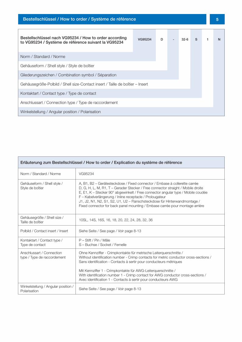
Bestellschlüssel nach VG95234 / How to order accordingto VG95234 / Système de référence suivant la VG95234
Norm / Standard / Norme
Gehäuseform / Shell style / Style de boîtier
Gliederungszeichen / Combination symbol / Séparation
Gehäusegröße-Polbild / Shell size-Contact insert / Taille de boîtier – Insert
Kontaktart / Contact type / Type de contact
Anschlussart / Connection type / Type de raccordement
Winkelstellung / Angular position / Polarisation
VG95234 D - 32-6 S 1 N
Erläuterung zum Bestellschlüssel / How to order / Explication du système de référence
Norm / Standard / Norme VG95234
Gehäuseform / Shell style / A, B1, B2 – Gerätesteckdose / Fixed connector / Embase à collerette carréeStyle de boîtier D, G, H, L, M, R1, T – Gerader Stecker / Free connector straight / Mobile droite
E, E1, K – Stecker 90° abgewinkelt / Free connector angular type / Mobile coudéeF – Kabelverlängerung / Inline receptacle / ProlougateurJ1, J2, N1, N2, S1, S2, U1, U2 – Flanschsteckdose für Hinterwandmontage / Fixed connector for back panel mounting / Embase carrée pour montage arrière
Gehäusegröße / Shell size / Taille de boîtier 10SL, 14S, 16S, 16, 18, 20, 22, 24, 28, 32, 36
Polbild / Contact insert / Insert Siehe Seite / See page / Voir page 8-13
Kontaktart / Contact type / P – Stift / Pin / MâleType de contact S – Buchse / Socket / Femelle
Anschlussart / Connection Ohne Kennziffer - Crimpkontakte für metrische Leiterquerschnitte / type / Type de raccordement Without identification number - Crimp contacts for metric conductor cross-sections /
Sans identification - Contacts à sertir pour conducteurs métriques
Mit Kennziffer 1 - Crimpkontakte für AWG-Leiterquerschnitte / With identification number 1 - Crimp contact for AWG conductor cross-sections / Avec identification 1 - Contacts à sertir pour conducteurs AWG
Winkelstellung / Angular position /Polarisation Siehe Seite / See page / Voir page 8-13
0298_ailb_kat.neu.411 04.03.2005 14:21 Uhr Seite 5
6 Bestellschlüssel / How to order / Système de référence
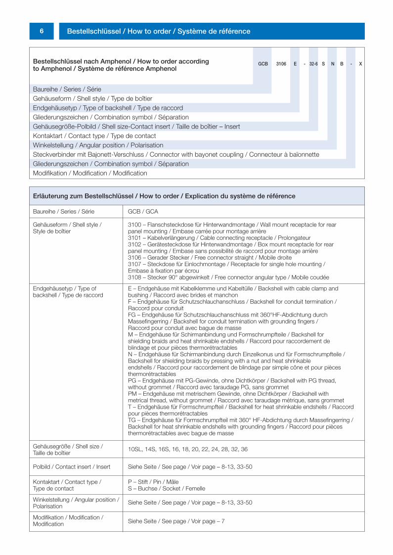
Bestellschlüssel nach Amphenol / How to order accordingto Amphenol / Système de référence Amphenol
Baureihe / Series / SérieGehäuseform / Shell style / Type de boîtierEndgehäusetyp / Type of backshell / Type de raccordGliederungszeichen / Combination symbol / SéparationGehäusegröße-Polbild / Shell size-Contact insert / Taille de boîtier – InsertKontaktart / Contact type / Type de contactWinkelstellung / Angular position / PolarisationSteckverbinder mit Bajonett-Verschluss / Connector with bayonet coupling / Connecteur à baïonnetteGliederungszeichen / Combination symbol / SéparationModifikation / Modification / Modification
GCB 3106 E - 32-6 S N B - X
Erläuterung zum Bestellschlüssel / How to order / Explication du système de référence
Baureihe / Series / Série GCB / GCA
Gehäuseform / Shell style / 3100 – Flanschsteckdose für Hinterwandmontage / Wall mount receptacle for rear Style de boîtier panel mounting / Embase carrée pour montage arrière
3101 – Kabelverlängerung / Cable connecting receptacle / Prolongateur3102 – Gerätesteckdose für Hinterwandmontage / Box mount receptacle for rear panel mounting / Embase sans possibilité de raccord pour montage arrière3106 – Gerader Stecker / Free connector straight / Mobile droite3107 – Steckdose für Einlochmontage / Receptacle for single hole mounting / Embase à fixation par écrou 3108 – Stecker 90° abgewinkelt / Free connector angular type / Mobile coudée
Endgehäusetyp / Type of E – Endgehäuse mit Kabelklemme und Kabeltülle / Backshell with cable clamp and backshell / Type de raccord bushing / Raccord avec brides et manchon
F – Endgehäuse für Schutzschlauchanschluss / Backshell for conduit termination / Raccord pour conduitFG – Endgehäuse für Schutzschlauchanschluss mit 360°HF-Abdichtung durch Massefingerring / Backshell for conduit termination with grounding fingers / Raccord pour conduit avec bague de masseM – Endgehäuse für Schirmanbindung und Formschrumpfteile / Backshell for shielding braids and heat shrinkable endshells / Raccord pour raccordement de blindage et pour pièces thermorétractablesN – Endgehäuse für Schirmanbindung durch Einzelkonus und für Formschrumpfteile / Backshell for shielding braids by pressing with a nut and heat shrinkable endshells / Raccord pour raccordement de blindage par simple cône et pour pièces thermorétractablesPG – Endgehäuse mit PG-Gewinde, ohne Dichtkörper / Backshell with PG thread, without grommet / Raccord avec taraudage PG, sans grommetPM – Endgehäuse mit metrischem Gewinde, ohne Dichtkörper / Backshell with metrical thread, without grommet / Raccord avec taraudage métrique, sans grommetT – Endgehäuse für Formschrumpfteil / Backshell for heat shrinkable endshells / Raccord pour pièces thermorétractablesTG – Endgehäuse für Formschrumpfteil mit 360° HF-Abdichtung durch Massefingerring / Backshell for heat shrinkable endshells with grounding fingers / Raccord pour pièces thermorétractables avec bague de masse
Gehäusegröße / Shell size / Taille de boîtier
10SL, 14S, 16S, 16, 18, 20, 22, 24, 28, 32, 36
Polbild / Contact insert / Insert Siehe Seite / See page / Voir page – 8-13, 33-50
Kontaktart / Contact type / P – Stift / Pin / MâleType de contact S – Buchse / Socket / Femelle
Winkelstellung / Angular position /Polarisation
Siehe Seite / See page / Voir page – 8-13, 33-50
Modifikation / Modification / Siehe Seite / See page / Voir page – 7 Modification
0298_ailb_kat.neu.411 04.03.2005 14:21 Uhr Seite 6
7Bestellschlüssel / How to order / Système de référence
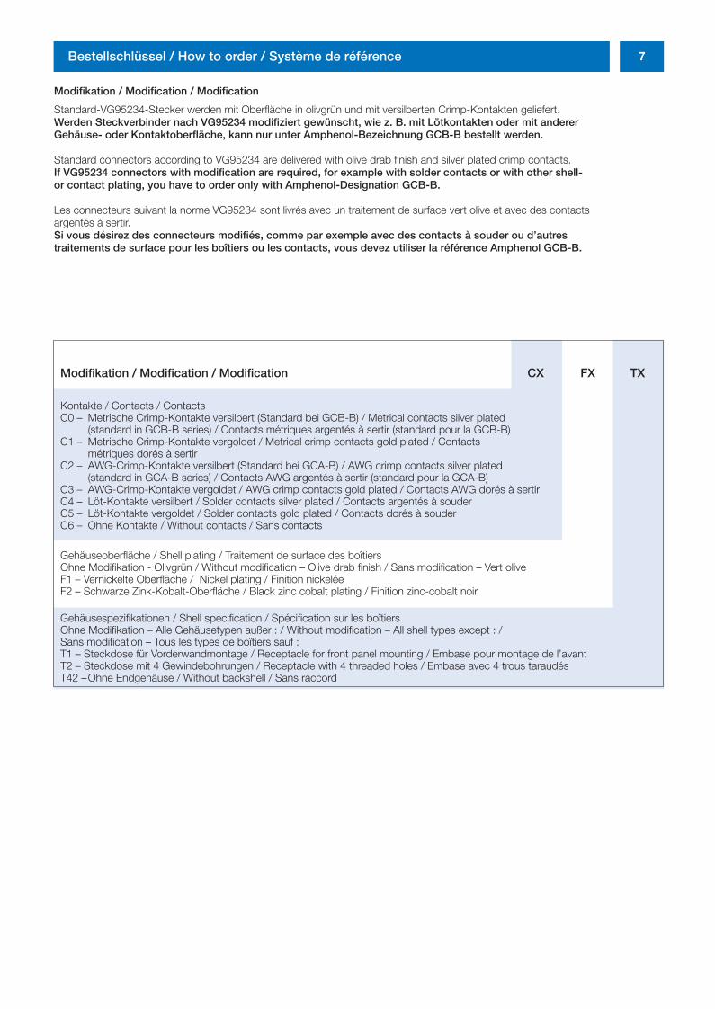
Modifikation / Modification / Modification
Standard-VG95234-Stecker werden mit Oberfläche in olivgrün und mit versilberten Crimp-Kontakten geliefert.Werden Steckverbinder nach VG95234 modifiziert gewünscht, wie z. B. mit Lötkontakten oder mit anderer Gehäuse- oder Kontaktoberfläche, kann nur unter Amphenol-Bezeichnung GCB-B bestellt werden.
Standard connectors according to VG95234 are delivered with olive drab finish and silver plated crimp contacts.If VG95234 connectors with modification are required, for example with solder contacts or with other shell- or contact plating, you have to order only with Amphenol-Designation GCB-B.
Les connecteurs suivant la norme VG95234 sont livrés avec un traitement de surface vert olive et avec des contacts argentés à sertir.Si vous désirez des connecteurs modifiés, comme par exemple avec des contacts à souder ou d’autres traitements de surface pour les boîtiers ou les contacts, vous devez utiliser la référence Amphenol GCB-B.
Modifikation / Modification / Modification CX FX TX
Kontakte / Contacts / ContactsC0 – Metrische Crimp-Kontakte versilbert (Standard bei GCB-B) / Metrical contacts silver plated
(standard in GCB-B series) / Contacts métriques argentés à sertir (standard pour la GCB-B) C1 – Metrische Crimp-Kontakte vergoldet / Metrical crimp contacts gold plated / Contacts
métriques dorés à sertirC2 – AWG-Crimp-Kontakte versilbert (Standard bei GCA-B) / AWG crimp contacts silver plated
(standard in GCA-B series) / Contacts AWG argentés à sertir (standard pour la GCA-B)C3 – AWG-Crimp-Kontakte vergoldet / AWG crimp contacts gold plated / Contacts AWG dorés à sertirC4 – Löt-Kontakte versilbert / Solder contacts silver plated / Contacts argentés à souderC5 – Löt-Kontakte vergoldet / Solder contacts gold plated / Contacts dorés à souderC6 – Ohne Kontakte / Without contacts / Sans contacts
Gehäuseoberfläche / Shell plating / Traitement de surface des boîtiersOhne Modifikation - Olivgrün / Without modification – Olive drab finish / Sans modification – Vert oliveF1 – Vernickelte Oberfläche / Nickel plating / Finition nickeléeF2 – Schwarze Zink-Kobalt-Oberfläche / Black zinc cobalt plating / Finition zinc-cobalt noir
Gehäusespezifikationen / Shell specification / Spécification sur les boîtiersOhne Modifikation – Alle Gehäusetypen außer : / Without modification – All shell types except : / Sans modification – Tous les types de boîtiers sauf : T1 – Steckdose für Vorderwandmontage / Receptacle for front panel mounting / Embase pour montage de l’avantT2 – Steckdose mit 4 Gewindebohrungen / Receptacle with 4 threaded holes / Embase avec 4 trous taraudésT42 –Ohne Endgehäuse / Without backshell / Sans raccord
0298_ailb_kat.neu.411 04.03.2005 14:21 Uhr Seite 7
8 VG95234 / GCB-B – Polbilder / Contact arrangements / Arrangements
Winkelstellung / Angular position / Polarisation
Winkelstellung der Kontakteinsätze / Angular position of the contact inserts / Polarisation des inserts
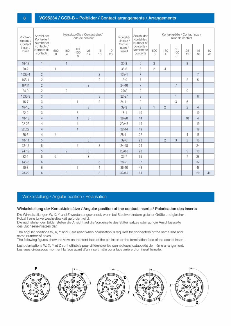
Die Winkelstellungen W, X, Y und Z werden angewendet, wenn bei Steckverbindern gleicher Größe und gleicher Polzahl eine Unverwechselbarkeit gefordert wird.Die nachstehenden Bilder stellen die Ansicht auf die Vorderseite des Stifteinsatzes oder auf die Anschlussseite des Buchseneinsatzes dar.
The angular positions W, X, Y and Z are used when polarisation is required for connectors of the same size and same number of poles.The following figures show the view on the front face of the pin insert or the termination face of the socket insert.
Les polarisations W, X, Y et Z sont utilisées pour différencier les connecteurs juxtaposés de même arrangement.Les vues ci-dessous montrent la face avant d’un insert mâle ou la face arrière d’un insert femelle.
Kontakt-einsatz /Contactinsert /Insert
Anzahl derKontakte /Number ofcontacts /Nombre de
contacts
Kontaktgröße / Contact size /Taille de contact
5000
1604
601008
2512
1516
1020
Kontakt-einsatz /Contactinsert /Insert
Anzahl derKontakte /Number ofcontacts /Nombre de
contacts
Kontaktgröße / Contact size /Taille de contact
5000
1604
601008
2512
1516
1020
16-12 1 1 36-3 6 3 3
20-2 1 1 36-6 6 2 4
10SL-4 2 2 16S-1 7 7
16S-4 2 2 18-9 7 2 5
16A11 2 2 24-10 7 7
24-9 2 2 20A9 9 9
10SL-3 3 3 22-27 9 1 8
16-7 3 1 2 24-11 9 3 6
16-10 3 3 32-3 9 1 2 2 4
22-2 3 3 18-1 10 10
18-13 4 1 3 28-20 14 10 4
22-22 4 4 20A48 19 19
22B22 4 4 22-14 19 19
36-5 4 4 28-11 22 4 18
18-11 5 5 32-6 23 2 3 2 16
22-12 5 2 3 24-28 24 24
24-12 5 2 3 28A63 28 9 19
32-1 5 2 3 32-7 35 7 28
14S-6 6 6 28-21 37 37
20-8 6 2 4 36-10 48 48
28-22 6 3 3 32A69 61 20 41
0298_ailb_kat.neu.411 04.03.2005 14:21 Uhr Seite 8
9VG95234 / GCB-B – Polbilder / Contact arrangements / Arrangements
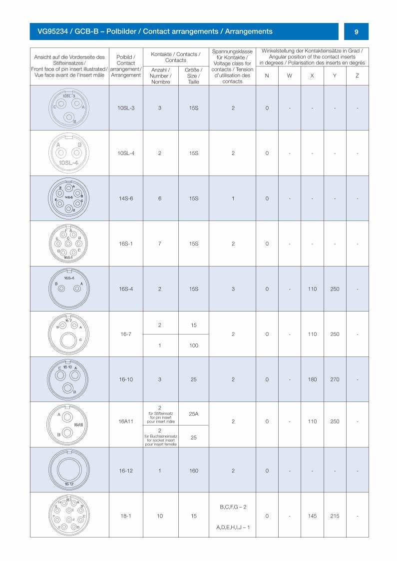
Ansicht auf die Vorderseite desStifteinsatzes/
Front face of pin insert illustrated/Vue face avant de l’insert mâle
Polbild /Contact
arrangement/Arrangement
Kontakte / Contacts /Contacts
Spannungsklassefür Kontakte /
Voltage class forcontacts / Tension
d’utilisation descontacts
Winkelstellung der Kontakteinsätze in Grad /Angular position of the contact inserts
in degrees / Polarisation des inserts en degrésAnzahl /
Number /Nombre
Größe /Size /Taille
N W X Y Z
10SL-3 3 15S 2 0 - - - -
10SL-4 2 15S 2 0 - - - -
14S-6 6 15S 1 0 - - - -
16S-1 7 15S 2 0 - - - -
16S-4 2 15S 3 0 - 110 250 -
16-7
2 15
2 0 - 110 250 -
1 100
16-10 3 25 2 0 - 180 270 -
16A11
225A
2 0 - 110 250 -
225
16-12 1 160 2 0 - - - -
18-1 10 15
B,C,F,G – 2
0 - 145 215 -
A,D,E,H,I,J – 1
für Stifteinsatzfor pin insert
pour insert mâle
für Buchseneinsatz for socket insert
pour insert femelle
0298_ailb_kat.neu.411 04.03.2005 14:21 Uhr Seite 9
10 VG95234 / GCB-B – Polbilder / Contact arrangements / Arrangements
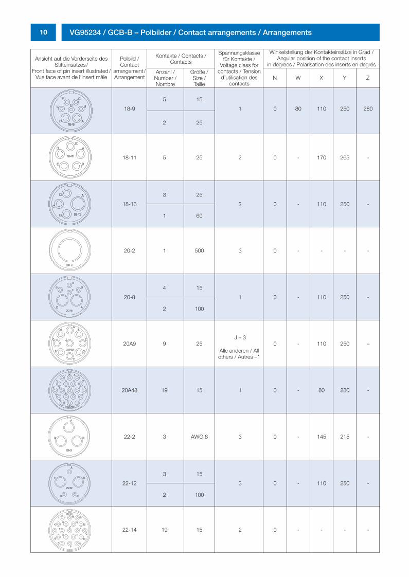
Ansicht auf die Vorderseite desStifteinsatzes/
Front face of pin insert illustrated/Vue face avant de l’insert mâle
Polbild /Contact
arrangement/Arrangement
Kontakte / Contacts /Contacts
Spannungsklassefür Kontakte /
Voltage class forcontacts / Tension
d’utilisation descontacts
Winkelstellung der Kontakteinsätze in Grad /Angular position of the contact inserts
in degrees / Polarisation des inserts en degrésAnzahl /
Number /Nombre
Größe /Size /Taille
N W X Y Z
18-9
5 15
1 0 80 110 250 280
2 25
18-11 5 25 2 0 - 170 265 -
18-13
3 25
2 0 - 110 250 -
1 60
20-2 1 500 3 0 - - - -
20-8
4 15
1 0 - 110 250 -
2 100
20A9 9 25J – 3
0 - 110 250 –
20A48 19 15 1 0 - 80 280 -
22-2 3 AWG 8 3 0 - 145 215 -
22-12
3 15
3 0 - 110 250 -
2 100
22-14 19 15 2 0 - - - -
Alle anderen / Allothers / Autres –1
0298_ailb_kat.neu.411 04.03.2005 14:21 Uhr Seite 10
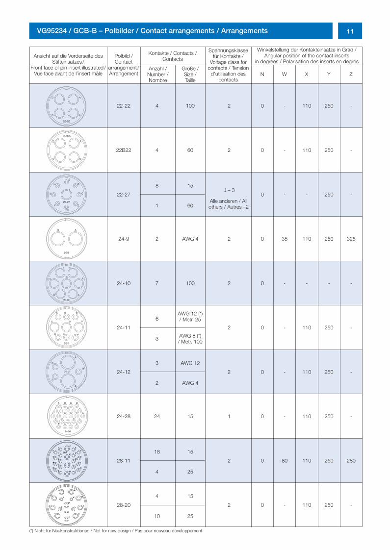
11VG95234 / GCB-B – Polbilder / Contact arrangements / Arrangements
Ansicht auf die Vorderseite desStifteinsatzes/
Front face of pin insert illustrated/Vue face avant de l’insert mâle
Polbild /Contact
arrangement/Arrangement
Kontakte / Contacts /Contacts
Spannungsklassefür Kontakte /
Voltage class forcontacts / Tension
d’utilisation descontacts
Winkelstellung der Kontakteinsätze in Grad /Angular position of the contact inserts
in degrees / Polarisation des inserts en degrésAnzahl /
Number /Nombre
Größe /Size /Taille
N W X Y Z
22-22 4 100 2 0 - 110 250 -
22B22 4 60 2 0 - 110 250 -
22-27
8 15J – 3
0 - - 250 -
1 60
24-9 2 AWG 4 2 0 35 110 250 325
24-10 7 100 2 0 - - - -
24-11
6
2 0 - 110 250 -
3
24-12
3 AWG 12
2 0 - 110 250 -
2 AWG 4
24-28 24 15 1 0 - 110 250 -
28-11
18 15
2 0 80 110 250 280
4 25
28-20
4 15
2 0 - 110 250 -
10 25
(*) Nicht für Neukonstruktionen / Not for new design / Pas pour nouveau développement
Alle anderen / Allothers / Autres –2
AWG 12 (*)/ Metr. 25
AWG 8 (*)/ Metr. 100
0298_ailb_kat.neu.411 04.03.2005 14:21 Uhr Seite 11
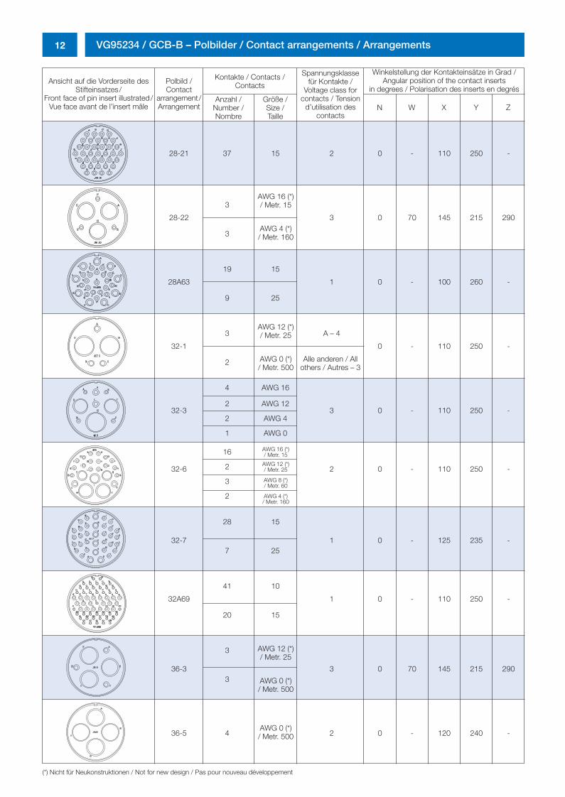
12 VG95234 / GCB-B – Polbilder / Contact arrangements / Arrangements
Ansicht auf die Vorderseite desStifteinsatzes/
Front face of pin insert illustrated/Vue face avant de l’insert mâle
Polbild /Contact
arrangement/Arrangement
Kontakte / Contacts /Contacts
Spannungsklassefür Kontakte /
Voltage class forcontacts / Tension
d’utilisation descontacts
Winkelstellung der Kontakteinsätze in Grad /Angular position of the contact inserts
in degrees / Polarisation des inserts en degrésAnzahl /
Number /Nombre
Größe /Size /Taille
N W X Y Z
28-21 37 15 2 0 - 110 250 -
28-22
3
3 0 70 145 215 290
3
28A63
19 15
1 0 - 100 260 -
9 25
32-1
3 A – 4
0 - 110 250 -
2
32-3
4 AWG 16
3 0 - 110 250 -2 AWG 12
2 AWG 4
1 AWG 0
32-6
16
2 0 - 110 250 -2
3
2
32-7
28 15
1 0 - 125 235 -7 25
32A69
41 10
1 0 - 110 250 -
20 15
36-3
3
3 0 70 145 215 2903
36-5 4 2 0 - 120 240 -
(*) Nicht für Neukonstruktionen / Not for new design / Pas pour nouveau développement
Alle anderen / Allothers / Autres – 3
AWG 16 (*)/ Metr. 15
AWG 4 (*)/ Metr. 160
AWG 12 (*)/ Metr. 25
AWG 0 (*)/ Metr. 500
AWG 12 (*)/ Metr. 25
AWG 0 (*)/ Metr. 500
AWG 0 (*)/ Metr. 500
AWG 16 (*)/ Metr. 15
AWG 12 (*)/ Metr. 25
AWG 8 (*)/ Metr. 60
AWG 4 (*)/ Metr. 160
0298_ailb_kat.neu.411 04.03.2005 14:21 Uhr Seite 12
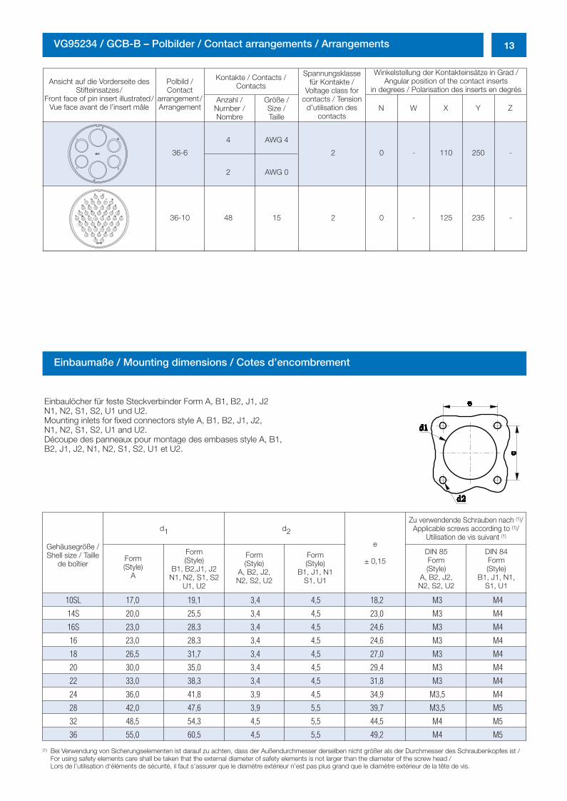
13VG95234 / GCB-B – Polbilder / Contact arrangements / Arrangements
Ansicht auf die Vorderseite desStifteinsatzes/
Front face of pin insert illustrated/Vue face avant de l’insert mâle
Polbild /Contact
arrangement/Arrangement
Kontakte / Contacts /Contacts
Spannungsklassefür Kontakte /
Voltage class forcontacts / Tension
d’utilisation descontacts
Winkelstellung der Kontakteinsätze in Grad /Angular position of the contact inserts
in degrees / Polarisation des inserts en degrésAnzahl /
Number /Nombre
Größe /Size /Taille
N W X Y Z
36-6
4 AWG 4
2 0 - 110 250 -
2 AWG 0
36-10 48 15 2 0 - 125 235 -
Einbaumaße / Mounting dimensions / Cotes d’encombrement
Einbaulöcher für feste Steckverbinder Form A, B1, B2, J1, J2N1, N2, S1, S2, U1 und U2.Mounting inlets for fixed connectors style A, B1, B2, J1, J2,N1, N2, S1, S2, U1 and U2.Découpe des panneaux pour montage des embases style A, B1,B2, J1, J2, N1, N2, S1, S2, U1 et U2.
Gehäusegröße /Shell size / Taille
de boîtierForm(Style)
A
Form(Style)
B1, B2,J1, J2N1, N2, S1, S2
U1, U2
Form(Style)
A, B2, J2,N2, S2, U2
Form(Style)
B1, J1, N1S1, U1
e
± 0,15DIN 85Form(Style)
A, B2, J2,N2, S2, U2
DIN 84Form(Style)
B1, J1, N1,S1, U1
Zu verwendende Schrauben nach (1)/Applicable screws according to (1)/
Utilisation de vis suivant (1)d1 d2
(1) Bei Verwendung von Sicherungselementen ist darauf zu achten, dass der Außendurchmesser derselben nicht größer als der Durchmesser des Schraubenkopfes ist /For using safety elements care shall be taken that the external diameter of safety elements is not larger than the diameter of the screw head /Lors de l’utilisation d‘éléments de sécurité, il faut s’assurer que le diamètre extérieur n’est pas plus grand que le diamètre extérieur de la tête de vis.
10SL 17,0 19,1 3,4 4,5 18,2 M3 M4
14S 20,0 25,5 3,4 4,5 23,0 M3 M4
16S 23,0 28,3 3,4 4,5 24,6 M3 M4
16 23,0 28,3 3,4 4,5 24,6 M3 M4
18 26,5 31,7 3,4 4,5 27,0 M3 M4
20 30,0 35,0 3,4 4,5 29,4 M3 M4
22 33,0 38,3 3,4 4,5 31,8 M3 M4
24 36,0 41,8 3,9 4,5 34,9 M3,5 M4
28 42,0 47,6 3,9 5,5 39,7 M3,5 M5
32 48,5 54,3 4,5 5,5 44,5 M4 M5
36 55,0 60,5 4,5 5,5 49,2 M4 M5
0298_ailb_kat.neu.411 04.03.2005 14:21 Uhr Seite 13
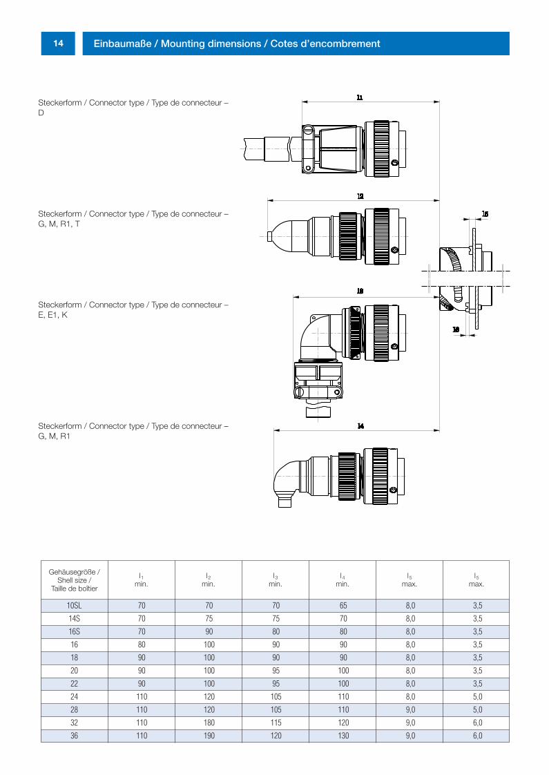
14 Einbaumaße / Mounting dimensions / Cotes d’encombrement
Gehäusegröße /Shell size /
Taille de boîtier
l1min.
l2min.
l3min.
l4min.
l5max.
l5max.
Steckerform / Connector type / Type de connecteur –D
Steckerform / Connector type / Type de connecteur –G, M, R1, T
Steckerform / Connector type / Type de connecteur –E, E1, K
Steckerform / Connector type / Type de connecteur –G, M, R1
10SL 70 70 70 65 8,0 3,5
14S 70 75 75 70 8,0 3,5
16S 70 90 80 80 8,0 3,5
16 80 100 90 90 8,0 3,5
18 90 100 90 90 8,0 3,5
20 90 100 95 100 8,0 3,5
22 90 100 95 100 8,0 3,5
24 110 120 105 110 8,0 5,0
28 110 120 105 110 9,0 5,0
32 110 180 115 120 9,0 6,0
36 110 190 120 130 9,0 6,0
0298_ailb_kat.neu.411 04.03.2005 14:21 Uhr Seite 14
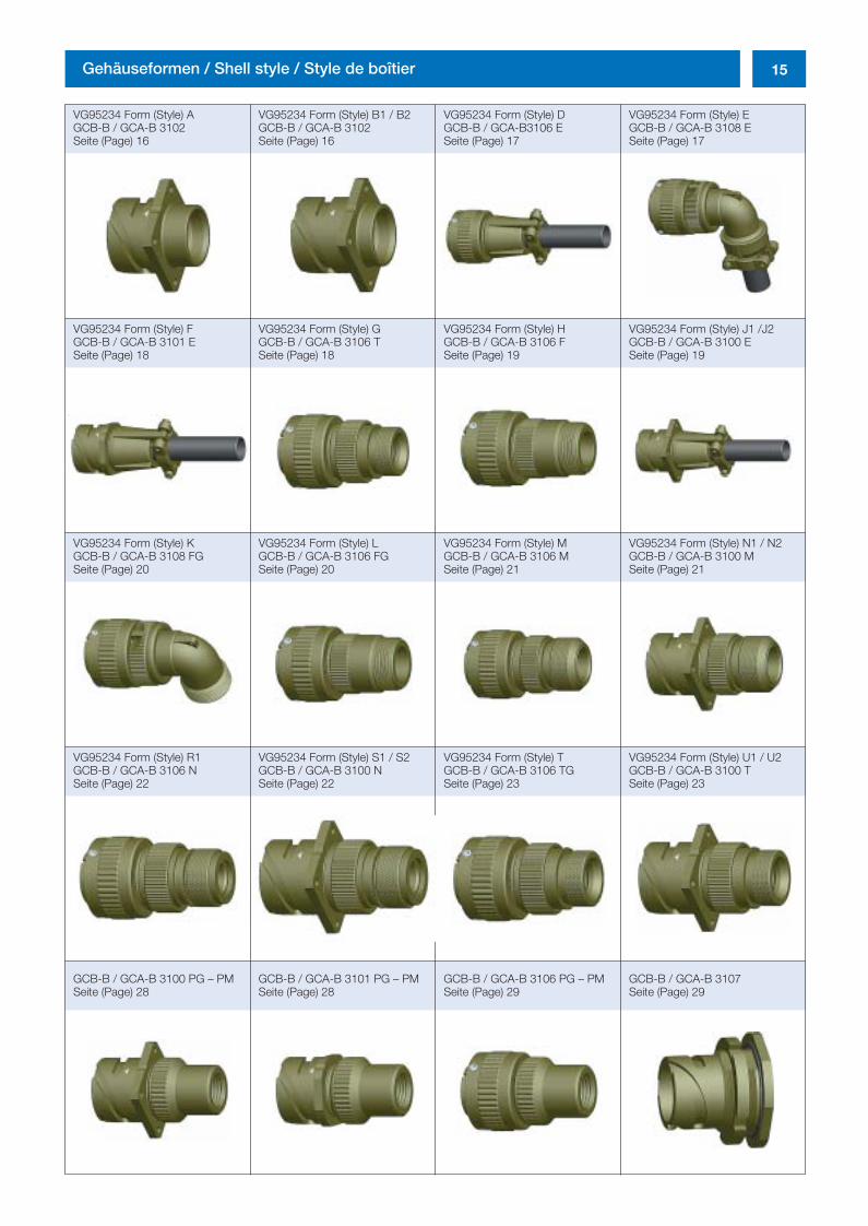
15Gehäuseformen / Shell style / Style de boîtier
VG95234 Form (Style) AGCB-B / GCA-B 3102Seite (Page) 16
VG95234 Form (Style) B1 / B2GCB-B / GCA-B 3102Seite (Page) 16
VG95234 Form (Style) DGCB-B / GCA-B3106 ESeite (Page) 17
VG95234 Form (Style) EGCB-B / GCA-B 3108 ESeite (Page) 17
VG95234 Form (Style) FGCB-B / GCA-B 3101 ESeite (Page) 18
VG95234 Form (Style) GGCB-B / GCA-B 3106 TSeite (Page) 18
VG95234 Form (Style) HGCB-B / GCA-B 3106 FSeite (Page) 19
VG95234 Form (Style) J1 /J2GCB-B / GCA-B 3100 ESeite (Page) 19
VG95234 Form (Style) KGCB-B / GCA-B 3108 FGSeite (Page) 20
VG95234 Form (Style) LGCB-B / GCA-B 3106 FGSeite (Page) 20
VG95234 Form (Style) MGCB-B / GCA-B 3106 MSeite (Page) 21
VG95234 Form (Style) N1 / N2GCB-B / GCA-B 3100 MSeite (Page) 21
VG95234 Form (Style) R1GCB-B / GCA-B 3106 NSeite (Page) 22
VG95234 Form (Style) S1 / S2GCB-B / GCA-B 3100 NSeite (Page) 22
VG95234 Form (Style) TGCB-B / GCA-B 3106 TGSeite (Page) 23
VG95234 Form (Style) U1 / U2GCB-B / GCA-B 3100 TSeite (Page) 23
GCB-B / GCA-B 3100 PG – PMSeite (Page) 28
GCB-B / GCA-B 3101 PG – PMSeite (Page) 28
GCB-B / GCA-B 3106 PG – PMSeite (Page) 29
GCB-B / GCA-B 3107 Seite (Page) 29
0298_ailb_kat.neu.411 04.03.2005 14:21 Uhr Seite 15
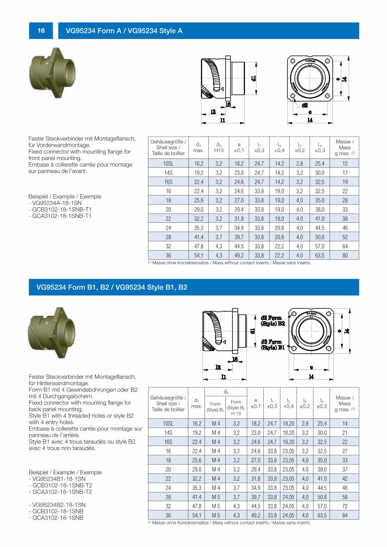
16 VG95234 Form A / VG95234 Style A
Fester Steckverbinder mit Montageflansch,für Vorderwandmontage.Fixed connector with mounting flange forfront panel mounting.Embase à collerette carrée pour montagesur panneau de l’avant.
Beispiel / Example / Exemple - VG95234A-18-1SN- GCB3102-18-1SNB-T1- GCA3102-18-1SNB-T1
Gehäusegröße /Shell size /
Taille de boîtier
d1
max.d2
H13e
±0,1l2
+0,4l1
±0,3l3
±0,2l4
±0,3
Masse /Mass
g max. (1)
(1) Masse ohne Kontakteinsätze / Mass without contact inserts / Masse sans inserts
10SL 16,2 3,2 18,2 24,7 14,2 2,8 25,4 12
14S 19,2 3,2 23,0 24,7 14,2 3,2 30,0 17
16S 22,4 3,2 24,6 24,7 14,2 3,2 32,5 19
16 22,4 3,2 24,6 33,8 19,0 3,2 32,5 22
18 25,6 3,2 27,0 33,8 19,0 4,0 35,0 28
20 29,0 3,2 29,4 33,8 19,0 4,0 38,0 33
22 32,2 3,2 31,8 33,8 19,0 4,0 41,0 38
24 35,3 3,7 34,9 33,8 20,6 4,0 44,5 46
28 41,4 3,7 39,7 33,8 20,6 4,0 50,8 52
32 47,8 4,3 44,5 33,8 22,2 4,0 57,0 64
36 54,1 4,3 49,2 33,8 22,2 4,0 63,5 80
VG95234 Form B1, B2 / VG95234 Style B1, B2
Fester Steckverbinder mit Montageflansch,für Hinterwandmontage.Form B1 mit 4 Gewindebohrungen oder B2mit 4 Durchgangslöchern.Fixed connector with mounting flange forback panel mounting.Style B1 with 4 threaded holes or style B2with 4 entry holes.Embase à collerette carrée pour montage surpanneau de l’arrière.Style B1 avec 4 trous taraudés ou style B2avec 4 trous non taraudés.
Gehäusegröße /Shell size /
Taille de boîtier
d1
max.e
±0,1l2
+0,4l1
±0,3l3
±0,2l4
±0,3
Masse /Mass
g max. (1)
(1) Masse ohne Kontakteinsätze / Mass without contact inserts / Masse sans inserts
10SL 16,2 M 4 3,2 18,2 24,7 18,20 2,8 25,4 14
14S 19,2 M 4 3,2 23,0 24,7 18,20 3,2 30,0 21
16S 22,4 M 4 3,2 24,6 24,7 18,20 3,2 32,5 22
16 22,4 M 4 3,2 24,6 33,8 23,05 3,2 32,5 27
18 25,6 M 4 3,2 27,0 33,8 23,05 4,0 35,0 33
20 29,0 M 4 3,2 29,4 33,8 23,05 4,0 38,0 37
22 32,2 M 4 3,2 31,8 33,8 23,05 4,0 41,0 42
24 35,3 M 4 3,7 34,9 33,8 23,05 4,0 44,5 48
28 41,4 M 5 3,7 39,7 33,8 24,05 4,0 50,8 58
32 47,8 M 5 4,3 44,5 33,8 24,05 4,0 57,0 72
36 54,1 M 5 4,3 49,2 33,8 24,05 4,0 63,5 84
Beispiel / Example / Exemple - VG95234B1-18-1SN- GCB3102-18-1SNB-T2- GCA3102-18-1SNB-T2
- VG95234B2-18-1SN- GCB3102-18-1SNB- GCA3102-18-1SNB
d2
Form(Style) B1
Form(Style) B2
H 13
0298_ailb_kat.neu.411 04.03.2005 14:21 Uhr Seite 16
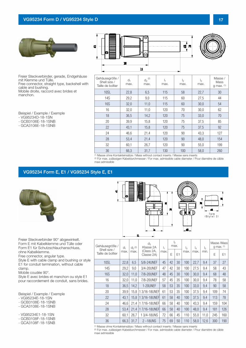
17VG95234 Form D / VG95234 Style D
Freier Steckverbinder, gerade, Endgehäusemit Klemme und Tülle.Free connector, straight type, backshell withcable and bushing.Mobile droite, raccord avec brides et manchon.
Beispiel / Example / Exemple - VG95234D-18-1SN- GCB3106E-18-1SNB- GCA3106E-18-1SNB
Gehäusegröße /Shell size /
Taille de boîtier
d1
max.d2
(2)
max.l1
max.l2
max.l3
max.
Masse /Mass
g max. (1)
(1) Masse ohne Kontakteinsätze / Mass without contact inserts / Masse sans inserts(2) Für max. zulässigen Kabeldurchmesser / For max. admissible cable diameter / Pour diamètre de câblemaxi admissible
(1) Masse ohne Kontakteinsätze / Mass without contact inserts / Masse sans inserts(2) Für max. zulässigen Kabeldurchmesser / For max. admissible cable diameter / Pour diamètre de câblemaxi admissible
10SL 22,8 6,5 115 58 22,7 30
14S 29,2 9,0 115 60 27,5 44
16S 32,0 11,0 115 60 30,0 54
16 32,0 11,0 120 70 30,0 62
18 36,5 14,2 120 75 33,0 70
20 39,9 15,8 120 75 37,5 85
22 43,1 15,8 120 75 37,5 92
24 46,6 21,4 120 90 43,3 127
28 53,4 21,4 120 90 48,0 154
32 60,1 26,7 120 90 55,0 199
36 66,3 31,7 130 100 58,0 260
VG95234 Form E, E1 / VG95234 Style E, E1
Freier Steckverbinder 90° abgewinkelt. Form E mit Kabelklemme und Tülle oderForm E1 für Schutzschlauchanschluss, ohne Kabelklemme.Free connector, angular type. Style E with cable clamp and bushing or styleE1 for conduit termination, without cableclamp.Mobile coudée 90°. Style E avec brides et manchon ou style E1pour raccordement de conduit, sans brides.
Beispiel / Example / Exemple - VG95234E-18-1SN- GCB3108E-18-1SNB- GCA3108E-18-1SNB
- VG95234E1-18-1SN- GCB3108F-18-1SNB- GCA3108F-18-1SNB
Gehäusegröße /Shell size /
Taille de boîtier
d3
Klasse 2A(Class 2A,Classe 2A)
d1
max.l1
max.l3
max.l4
max.l5
min.d2
(2)
max.
Masse /Massg max. (1)
10SL 22,8 6,5 5/8-24UNEF 45 42 30 100 22,7 9,4 37 27
14S 29,2 9,0 3/4-20UNEF 47 42 30 100 27,5 9,4 58 43
16S 32,0 11,0 7/8-20UNEF 48 45 30 100 30,0 9,4 68 48
16 32,0 11,0 7/8-20UNEF 57 45 35 100 30,0 9,4 78 58
18 36,5 14,2 1-20UNEF 58 53 35 100 33,0 9,4 90 58
20 39,9 15,8 1 3/16-18UNEF 61 53 35 100 37,5 9,4 109 74
22 43,1 15,8 1 3/16-18UNEF 61 58 40 100 37,5 9,4 113 78
24 46,6 21,4 1 7/16-18UNEF 66 58 40 100 43,3 9,4 159 104
28 53,4 21,4 1 7/16-18UNEF 66 58 40 100 48,0 9,4 181 126
32 60,1 26,7 1 3/4-18UNS 72 66 45 110 55,0 11,0 245 160
36 66,3 31,7 2 –18UNS 75 69 50 110 58,0 12,6 300 190
l2max.
E EE1 E1
0298_ailb_kat.neu.411 04.03.2005 14:21 Uhr Seite 17
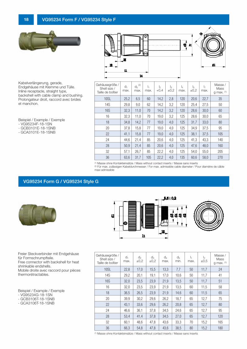
18 VG95234 Form F / VG95234 Style F
Gehäusegröße /Shell size /
Taille de boîtier
d1
max.l1
max.l4
max.l7
max.d2
(2)
max.l2
+0,4l3
±0,2l5
±0,2
Masse /Mass
g max. (1)
10SL 25,2 6,5 60 14,2 2,8 120 20,6 22,7 35
14S 29,8 9,0 62 14,2 3,2 120 25,4 27,5 50
16S 32,3 11,0 70 14,2 3,2 120 28,6 30,0 60
16 32,3 11,0 70 19,0 3,2 125 28,6 30,0 65
18 34,8 14,2 77 19,0 4,0 125 31,7 33,0 80
20 37,8 15,8 77 19,0 4,0 125 34,9 37,5 95
22 41,1 15,8 77 19,0 4,0 125 38,1 37,5 105
24 44,6 21,4 85 20,6 4,0 125 41,3 43,3 140
28 50,9 21,4 85 20,6 4,0 125 47,6 48,0 160
32 57,1 26,7 85 22,2 4,0 125 54,0 55,0 205
36 63,6 31,7 105 22,2 4,0 135 60,6 58,0 270
Kabelverlängerung, gerade, Endgehäuse mit Klemme und Tülle.Inline receptacle, straight type, backshell with cable clamp and bushing.Prolongateur droit, raccord avec brides et manchon.
Beispiel / Example / Exemple - VG95234F-18-1SN- GCB3101E-18-1SNB- GCA3101E-18-1SNB
(1) Masse ohne Kontakteinsätze / Mass without contact inserts / Masse sans inserts(2) Für max. zulässigen Kabeldurchmesser / For max. admissible cable diameter / Pour diamètre de câblemaxi admissible
VG95234 Form G / VG95234 Style G
Freier Steckverbinder mit Endgehäuse für Formschrumpfteile.Free connector with backshell for heat shrinkable endshells.Mobile droite avec raccord pour pièces thermorétractables.
Beispiel / Example / Exemple - VG95234G-18-1SN- GCB3106T-18-1SNB- GCA3106T-18-1SNB
(1) Masse ohne Kontakteinsätze / Mass without contact inserts / Masse sans inserts
Gehäusegröße /Shell size /
Taille de boîtier
d1
max.d2
±0,2d3
±0,2d4
max.d5
min.l1
max.l2
±0,5
Masse /Mass
g max. (1)
10SL 22,8 17,0 15,5 13,3 7,7 50 11,7 24
14S 29,2 20,1 19,1 17,0 10,6 50 11,7 41
16S 32,0 23,5 23,9 21,9 13,5 50 11,7 51
16 32,0 23,5 23,9 21,9 13,5 60 11,5 58
18 36,5 26,5 23,9 21,9 14,6 60 11,5 65
20 39,9 30,2 29,6 26,2 18,7 65 12,7 75
22 43,1 33,6 29,6 26,2 20,8 65 12,7 80
24 46,6 36,1 37,8 34,5 24,6 65 12,7 95
28 53,4 41,4 37,8 34,5 27,0 65 12,7 120
32 60,1 48,6 47,8 43,6 33,3 70 15,2 165
36 66,3 54,8 47,8 43,6 38,5 80 15,2 180
0298_ailb_kat.neu.411 04.03.2005 14:21 Uhr Seite 18
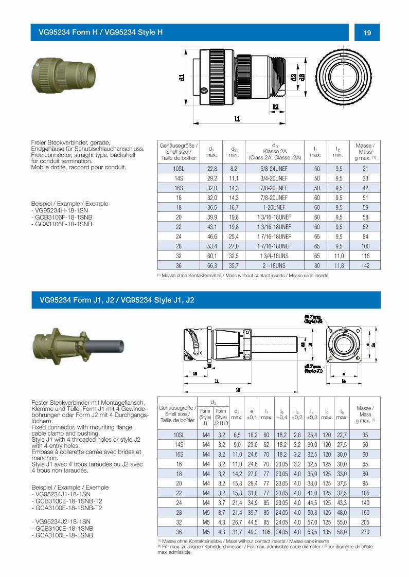
19VG95234 Form H / VG95234 Style H
Gehäusegröße /Shell size /
Taille de boîtier
d1
max.
d3
Klasse 2A(Class 2A, Classe 2A)
l 2
min.d2
min.l1
max.
Masse /Mass
g max. (1)
10SL 22,8 8,2 5/8-24UNEF 50 9,5 21
14S 29,2 11,1 3/4-20UNEF 50 9,5 33
16S 32,0 14,3 7/8-20UNEF 50 9,5 42
16 32,0 14,3 7/8-20UNEF 60 9,5 51
18 36,5 16,7 1-20UNEF 60 9,5 59
20 39,9 19,8 1 3/16-18UNEF 60 9,5 58
22 43,1 19,8 1 3/16-18UNEF 60 9,5 62
24 46,6 25,4 1 7/16-18UNEF 65 9,5 84
28 53,4 27,0 1 7/16-18UNEF 65 9,5 100
32 60,1 32,5 1 3/4-18UNS 65 11,0 116
36 66,3 35,7 2 –18UNS 80 11,8 142
Freier Steckverbinder, gerade, Endgehäuse für Schutzschlauchanschluss.Free connector, straight type, backshell for conduit termination.Mobile droite, raccord pour conduit.
Beispiel / Example / Exemple - VG95234H-18-1SN- GCB3106F-18-1SNB- GCA3106F-18-1SNB
(1) Masse ohne Kontakteinsätze / Mass without contact inserts / Masse sans inserts
(1) Masse ohne Kontakteinsätze / Mass without contact inserts / Masse sans inserts(2) Für max. zulässigen Kabeldurchmesser / For max. admissible cable diameter / Pour diamètre de câblemaxi admissible
VG95234 Form J1, J2 / VG95234 Style J1, J2
Fester Steckverbinder mit Montageflansch,Klemme und Tülle. Form J1 mit 4 Gewinde-bohrungen oder Form J2 mit 4 Durchgangs-löchern.Fixed connector, with mounting flange, cable clamp and bushing.Style J1 with 4 threaded holes or style J2with 4 entry holes.Embase à collerette carrée avec brides etmanchon.Style J1 avec 4 trous taraudés ou J2 avec 4 trous non taraudés.
Beispiel / Example / Exemple - VG95234J1-18-1SN- GCB3100E-18-1SNB-T2- GCA3100E-18-1SNB-T2
- VG95234J2-18-1SN- GCB3100E-18-1SNB- GCA3100E-18-1SNB
Gehäusegröße /Shell size /
Taille de boîtier
Form(Style)
J1
d3
max.e
±0,1l1
max.l2
+0,4l3
±0,2l4
±0,3l5
max.l6
max.Form(Style)J2 H13
Masse /Mass
g max. (1)
10SL M4 3,2 6,5 18,2 60 18,2 2,8 25,4 120 22,7 35
14S M4 3,2 9,0 23,0 62 18,2 3,2 30,0 120 27,5 50
16S M4 3,2 11,0 24,6 70 18,2 3,2 32,5 120 30,0 60
16 M4 3,2 11,0 24,6 70 23,05 3,2 32,5 125 30,0 65
18 M4 3,2 14,2 27,0 77 23,05 4,0 35,0 125 33,0 80
20 M4 3,2 15,8 29,4 77 23,05 4,0 38,0 125 37,5 95
22 M4 3,2 15,8 31,8 77 23,05 4,0 41,0 125 37,5 105
24 M4 3,7 21,4 34,9 85 23,05 4,0 44,5 125 43,3 140
28 M5 3,7 21,4 39,7 85 24,05 4,0 50,8 125 48,0 160
32 M5 4,3 26,7 44,5 85 24,05 4,0 57,0 125 55,0 205
36 M5 4,3 31,7 49,2 105 24,05 4,0 63,5 135 58,0 270
d2
0298_ailb_kat.neu.411 04.03.2005 14:21 Uhr Seite 19
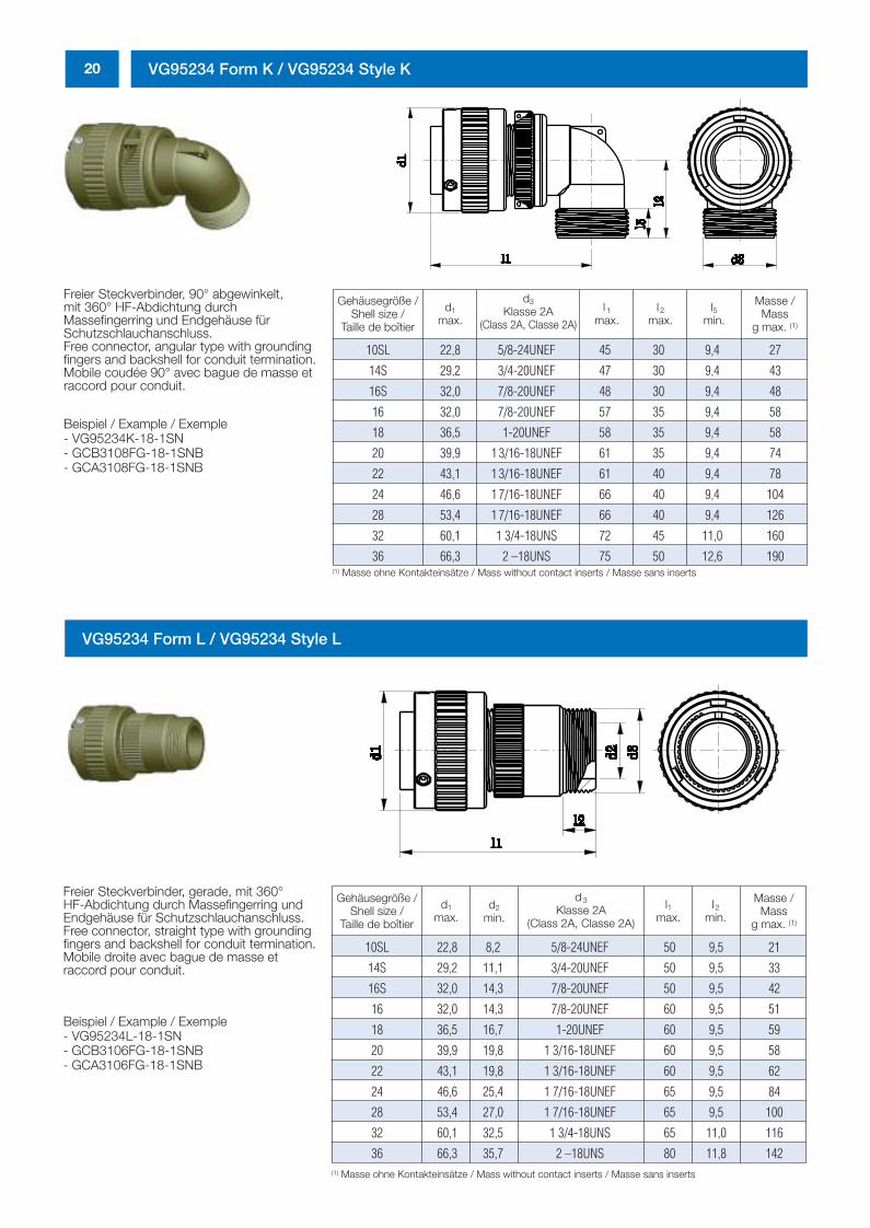
20 VG95234 Form K / VG95234 Style K
Freier Steckverbinder, 90° abgewinkelt, mit 360° HF-Abdichtung durch Massefingerring und Endgehäuse fürSchutzschlauchanschluss.Free connector, angular type with groundingfingers and backshell for conduit termination.Mobile coudée 90° avec bague de masse etraccord pour conduit.
Beispiel / Example / Exemple- VG95234K-18-1SN- GCB3108FG-18-1SNB- GCA3108FG-18-1SNB
Gehäusegröße /Shell size /
Taille de boîtier
d1
max.
d3
Klasse 2A(Class 2A, Classe 2A)
l 1
max.l 2
max.l5
min.
Masse /Mass
g max. (1)
(1) Masse ohne Kontakteinsätze / Mass without contact inserts / Masse sans inserts
10SL 22,8 5/8-24UNEF 45 30 9,4 27
14S 29,2 3/4-20UNEF 47 30 9,4 43
16S 32,0 7/8-20UNEF 48 30 9,4 48
16 32,0 7/8-20UNEF 57 35 9,4 58
18 36,5 1-20UNEF 58 35 9,4 58
20 39,9 1 3/16-18UNEF 61 35 9,4 74
22 43,1 1 3/16-18UNEF 61 40 9,4 78
24 46,6 1 7/16-18UNEF 66 40 9,4 104
28 53,4 1 7/16-18UNEF 66 40 9,4 126
32 60,1 1 3/4-18UNS 72 45 11,0 160
36 66,3 2 –18UNS 75 50 12,6 190
Gehäusegröße /Shell size /
Taille de boîtier
d1
max.
d3
Klasse 2A(Class 2A, Classe 2A)
l 2
min.d2
min.l1
max.
Masse /Mass
g max. (1)
10SL 22,8 8,2 5/8-24UNEF 50 9,5 21
14S 29,2 11,1 3/4-20UNEF 50 9,5 33
16S 32,0 14,3 7/8-20UNEF 50 9,5 42
16 32,0 14,3 7/8-20UNEF 60 9,5 51
18 36,5 16,7 1-20UNEF 60 9,5 59
20 39,9 19,8 1 3/16-18UNEF 60 9,5 58
22 43,1 19,8 1 3/16-18UNEF 60 9,5 62
24 46,6 25,4 1 7/16-18UNEF 65 9,5 84
28 53,4 27,0 1 7/16-18UNEF 65 9,5 100
32 60,1 32,5 1 3/4-18UNS 65 11,0 116
36 66,3 35,7 2 –18UNS 80 11,8 142
Freier Steckverbinder, gerade, mit 360°HF-Abdichtung durch Massefingerring undEndgehäuse für Schutzschlauchanschluss.Free connector, straight type with groundingfingers and backshell for conduit termination.Mobile droite avec bague de masse et raccord pour conduit.
Beispiel / Example / Exemple- VG95234L-18-1SN- GCB3106FG-18-1SNB- GCA3106FG-18-1SNB
(1) Masse ohne Kontakteinsätze / Mass without contact inserts / Masse sans inserts
VG95234 Form L / VG95234 Style L
0298_ailb_kat.neu.411 04.03.2005 14:21 Uhr Seite 20
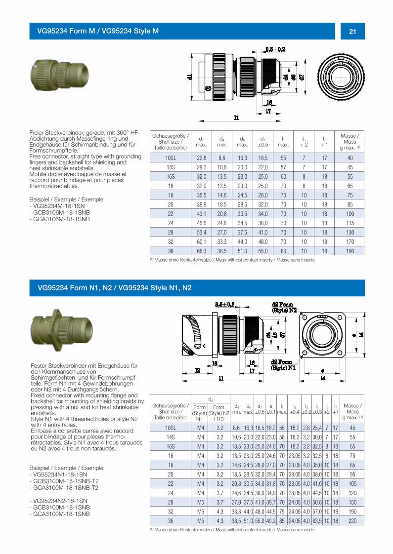
21VG95234 Form M / VG95234 Style M
Freier Steckverbinder, gerade, mit 360° HF-Abdichtung durch Massefingerring und Endgehäuse für Schirmanbindung und fürFormschrumpfteile.Free connector, straight type with groundingfingers and backshell for shielding andheat shrinkable endshells.Mobile droite avec bague de masse et raccord pour blindage et pour piècesthermorétractables.
Beispiel / Example / Exemple - VG95234M-18-1SN- GCB3106M-18-1SNB- GCA3106M-18-1SNB
(1) Masse ohne Kontakteinsätze / Mass without contact inserts / Masse sans inserts
Gehäusegröße /Shell size /
Taille de boîtier
d1
max.d4
min.d6
max.l1
max.d7
±0,5l6
+ 2l7
+ 1
Masse /Mass
g max. (1)
10SL 22,8 8,6 16,3 18,5 55 7 17 40
14S 29,2 10,6 20,0 22,0 57 7 17 45
16S 32,0 13,5 23,0 25,0 60 8 18 55
16 32,0 13,5 23,0 25,0 70 8 18 65
18 36,5 14,6 24,5 28,0 70 10 18 75
20 39,9 18,5 28,5 32,0 70 10 18 85
22 43,1 20,8 30,5 34,0 70 10 18 100
24 46,6 24,6 34,5 38,0 70 10 18 115
28 53,4 27,0 37,5 41,0 70 10 18 130
32 60,1 33,3 44,0 48,0 70 10 18 170
36 66,3 38,5 51,0 55,0 80 10 18 190
VG95234 Form N1, N2 / VG95234 Style N1, N2
(1) Masse ohne Kontakteinsätze / Mass without contact inserts / Masse sans inserts
Gehäusegröße /Shell size /
Taille de boîtier
Form(Style)
N1
Form(Style) N2
H13
d4
min.d6
max.d7
±0,5e
±0,1l1
max.l2
+0,4l3
±0,2l4
±0,3l6
+2l7
+1Masse /
Massg max. (1)
10SL M4 3,2 8,6 16,3 18,5 18,2 55 18,2 2,8 25,4 7 17 45
14S M4 3,2 10,6 20,0 22,0 23,0 58 18,2 3,2 30,0 7 17 55
16S M4 3,2 13,5 23,0 25,0 24,6 70 18,2 3,2 32,5 8 18 65
16 M4 3,2 13,5 23,0 25,0 24,6 70 23,05 3,2 32,5 8 18 75
18 M4 3,2 14,6 24,5 28,0 27,0 70 23,05 4,0 35,0 10 18 85
20 M4 3,2 18,5 28,5 32,0 29,4 70 23,05 4,0 38,0 10 18 95
22 M4 3,2 20,8 30,5 34,0 31,8 70 23,05 4,0 41,0 10 18 105
24 M4 3,7 24,6 34,5 38,0 34,9 70 23,05 4,0 44,5 10 18 120
28 M5 3,7 27,0 37,5 41,0 39,7 70 24,05 4,0 50,8 10 18 150
32 M5 4,3 33,3 44,0 48,0 44,5 75 24,05 4,0 57,0 10 18 190
36 M5 4,3 38,5 51,0 55,0 49,2 85 24,05 4,0 63,5 10 18 220
d2
Fester Steckverbinder mit Endgehäuse fürden Klemmanschluss vonSchirmgeflechten und für Formschrumpf-teile. Form N1 mit 4 Gewindebohrungenoder N2 mit 4 Durchgangslöchern.Fixed connector with mounting flange andbackshell for mounting of shielding braids bypressing with a nut and for heat shrinkableendshells.Style N1 with 4 threaded holes or style N2with 4 entry holes.Embase à collerette carrée avec raccordpour blindage et pour pièces thermo-rétractables. Style N1 avec 4 trous taraudésou N2 avec 4 trous non taraudés.
Beispiel / Example / Exemple - VG95234N1-18-1SN- GCB3100M-18-1SNB-T2- GCA3100M-18-1SNB-T2
- VG95234N2-18-1SN- GCB3100M-18-1SNB- GCA3100M-18-1SNB
0298_ailb_kat.neu.411 04.03.2005 14:21 Uhr Seite 21
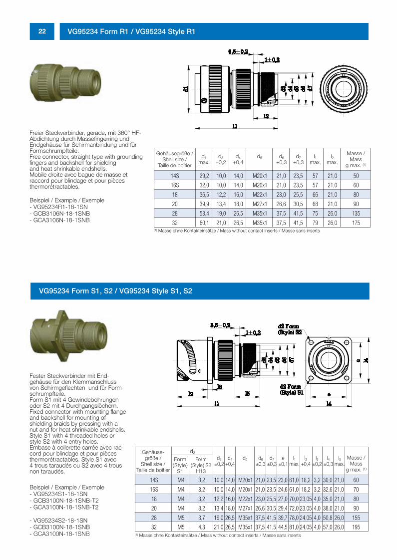
22 VG95234 Form R1 / VG95234 Style R1
Freier Steckverbinder, gerade, mit 360° HF-Abdichtung durch Massefingerring und Endgehäuse für Schirmanbindung und fürFormschrumpfteile.Free connector, straight type with groundingfingers and backshell for shieldingand heat shrinkable endshells.Mobile droite avec bague de masse et raccord pour blindage et pour piècesthermorétractables.
Beispiel / Example / Exemple - VG95234R1-18-1SN- GCB3106N-18-1SNB- GCA3106N-18-1SNB
(1) Masse ohne Kontakteinsätze / Mass without contact inserts / Masse sans inserts
Gehäusegröße /Shell size /
Taille de boîtier
d1
max.d3
+0,2d4
+0,4d5 d6
±0,3d7
±0,3l1
max.l2
max.
Masse /Mass
g max. (1)
14S 29,2 10,0 14,0 M20x1 21,0 23,5 57 21,0 50
16S 32,0 10,0 14,0 M20x1 21,0 23,5 57 21,0 60
18 36,5 12,2 16,0 M22x1 23,0 25,5 66 21,0 80
20 39,9 13,4 18,0 M27x1 26,6 30,5 68 21,0 90
28 53,4 19,0 26,5 M35x1 37,5 41,5 75 26,0 135
32 60,1 21,0 26,5 M35x1 37,5 41,5 79 26,0 175
(1) Masse ohne Kontakteinsätze / Mass without contact inserts / Masse sans inserts
Gehäuse-größe /
Shell size /Taille de boîtier
Form(Style)
S1
Form(Style) S2
H13
d3
±0,2d4
+0,4d5 d6
±0,3d7
±0,3e
±0,1l1
max.l2
+0,4l3
±0,2l4
±0,3l5
max.Masse /
Massg max. (1)
14S M4 3,2 10,0 14,0 M20x1 21,0 23,5 23,0 61,0 18,2 3,2 30,0 21,0 60
16S M4 3,2 10,0 14,0 M20x1 21,0 23,5 24,6 61,0 18,2 3,2 32,6 21,0 70
18 M4 3,2 12,2 16,0 M22x1 23,0 25,5 27,0 70,0 23,05 4,0 35,0 21,0 80
20 M4 3,2 13,4 18,0 M27x1 26,6 30,5 29,4 72,0 23,05 4,0 38,0 21,0 90
28 M5 3,7 19,0 26,5 M35x1 37,5 41,5 39,7 78,0 24,05 4,0 50,8 26,0 155
32 M5 4,3 21,0 26,5 M35x1 37,5 41,5 44,5 81,0 24,05 4,0 57,0 26,0 195
d2
VG95234 Form S1, S2 / VG95234 Style S1, S2
Fester Steckverbinder mit End-gehäuse für den Klemmanschlussvon Schirmgeflechten und für Form-schrumpfteile. Form S1 mit 4 Gewindebohrungenoder S2 mit 4 Durchgangslöchern.Fixed connector with mounting flangeand backshell for mounting ofshielding braids by pressing with anut and for heat shrinkable endshells.Style S1 with 4 threaded holes orstyle S2 with 4 entry holes.Embase à collerette carrée avec rac-cord pour blindage et pour piècesthermorétractables. Style S1 avec 4 trous taraudés ou S2 avec 4 trousnon taraudés.
Beispiel / Example / Exemple - VG95234S1-18-1SN- GCB3100N-18-1SNB-T2- GCA3100N-18-1SNB-T2
- VG95234S2-18-1SN- GCB3100N-18-1SNB- GCA3100N-18-1SNB
0298_ailb_kat.neu.411 04.03.2005 14:21 Uhr Seite 22
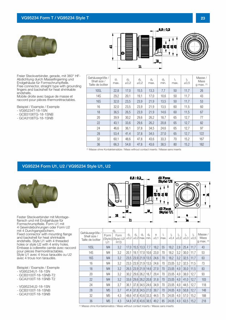
23VG95234 Form T / VG95234 Style T
Freier Steckverbinder, gerade, mit 360° HF-Abdichtung durch Massefingerring und Endgehäuse für Formschrumpfteile.Free connector, straight type with groundingfingers and backshell for heat shrinkableendshells.Mobile droite avec bague de masse et raccord pour pièces thermorétractables.
Beispiel / Example / Exemple - VG95234T-18-1SN- GCB3106TG-18-1SNB- GCA3106TG-18-1SNB
VG95234 Form U1, U2 / VG95234 Style U1, U2
(1) Masse ohne Kontakteinsätze / Mass without contact inserts / Masse sans inserts
Gehäusegröße /Shell size /
Taille de boîtier
d1
max.d5
min.d4
max.l1
max.d2
±0,2l2
±0,5d3
±0,2
Masse /Mass
g max. (1)
10SL 22,8 17,0 15,5 13,3 7,7 50 11,7 26
14S 29,2 20,1 19,1 17,0 10,6 50 11,7 43
16S 32,0 23,5 23,9 21,9 13,5 50 11,7 53
16 32,0 23,5 23,9 21,9 13,5 60 11,5 60
18 36,5 26,5 23,9 21,9 14,6 60 11,5 67
20 39,9 30,2 29,6 26,2 18,7 65 12,7 77
22 43,1 33,6 29,6 26,2 20,8 65 12,7 82
24 46,6 36,1 37,8 34,5 24,6 65 12,7 97
28 53,4 41,4 37,8 34,5 27,0 65 12,7 122
32 60,1 48,6 47,8 43,6 33,3 70 15,2 167
36 66,3 54,8 47,8 43,6 38,5 80 15,2 182
(1) Masse ohne Kontakteinsätze / Mass without contact inserts / Masse sans inserts
Gehäusegröße /Shell size /
Taille de boîtierForm(Style)
U1
Form(Style) U2
H13
d3
±0,2d4
±0,2d5
max.d6
min.e
±0,1l1
max.l2
+0,4l3
±0,2l4
±0,3l5
±0,5Masse /
Massg max. (1)
10SL M4 3,2 17,0 15,5 13,3 7,7 18,2 55 18,2 2,8 25,4 11,7 43
14S M4 3,2 20,1 19,1 17,0 10,6 23,0 70 18,2 3,2 30,0 11,7 53
16S M4 3,2 23,5 23,9 21,9 13,5 24,6 70 18,2 3,2 32,5 11,7 63
16 M4 3,2 23,5 23,9 21,9 13,5 24,6 70 23,05 3,2 32,5 11,5 73
18 M4 3,2 26,5 23,9 21,9 14,6 27,0 70 23,05 4,0 35,0 11,5 83
20 M4 3,2 30,2 29,6 26,2 18,7 29,4 70 23,05 4,0 38,0 12,7 93
22 M4 3,2 33,6 29,6 26,2 20,8 31,8 70 23,05 4,0 41,0 12,7 103
24 M4 3,7 36,1 37,8 34,5 24,6 34,9 70 23,05 4,0 44,5 12,7 118
28 M5 3,7 41,4 37,8 34,5 27,0 39,7 70 24,05 4,0 50,8 12,7 148
32 M5 4,3 48,6 47,8 43,6 33,3 44,5 75 24,05 4,0 57,0 15,2 188
36 M5 4,3 54,8 47,8 43,6 38,5 49,2 85 24,05 4,0 63,5 15,2 218
d2
Fester Steckverbinder mit Montage-flansch und mit Endgehäuse für Formschrumpfteile. Form U1 mit 4 Gewindebohrungen oder Form U2 mit 4 Durchgangslöchern.Fixed connector with mounting flangeand backshell for heat shrinkable endshells. Style U1 with 4 threadedholes or style U2 with 4 entry holes.Embase à collerette carrée avec raccordpour pièces thermorétractables.Style U1 avec 4 trous taraudés ou U2avec 4 trous non taraudés.
Beispiel / Example / Exemple - VG95234U1-18-1SN- GCB3100T-18-1SNB-T2- GCA3100T-18-1SNB-T2
- VG95234U2-18-1SN- GCB3100T-18-1SNB- GCA3100T-18-1SNB
0298_ailb_kat.neu.411 04.03.2005 14:21 Uhr Seite 23
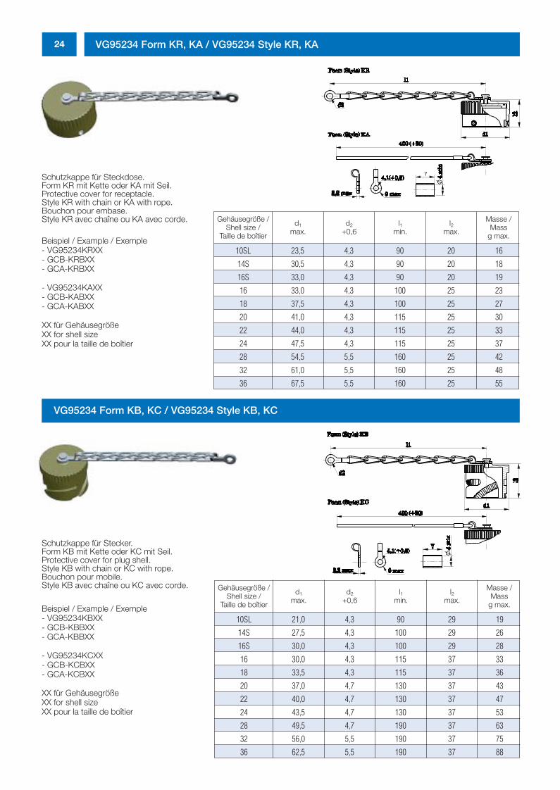
24 VG95234 Form KR, KA / VG95234 Style KR, KA
Schutzkappe für Steckdose.Form KR mit Kette oder KA mit Seil.Protective cover for receptacle.Style KR with chain or KA with rope.Bouchon pour embase.Style KR avec chaîne ou KA avec corde.
Beispiel / Example / Exemple - VG95234KRXX- GCB-KRBXX- GCA-KRBXX
- VG95234KAXX- GCB-KABXX- GCA-KABXX
XX für GehäusegrößeXX for shell sizeXX pour la taille de boîtier
Gehäusegröße /Shell size /
Taille de boîtier
d1
max.d2
+0,6l1
min.l2
max.
Masse /Mass
g max.
10SL 23,5 4,3 90 20 16
14S 30,5 4,3 90 20 18
16S 33,0 4,3 90 20 19
16 33,0 4,3 100 25 23
18 37,5 4,3 100 25 27
20 41,0 4,3 115 25 30
22 44,0 4,3 115 25 33
24 47,5 4,3 115 25 37
28 54,5 5,5 160 25 42
32 61,0 5,5 160 25 48
36 67,5 5,5 160 25 55
Gehäusegröße /Shell size /
Taille de boîtier
d1
max.d2
+0,6l1
min.l2
max.
Masse /Mass
g max.
10SL 21,0 4,3 90 29 19
14S 27,5 4,3 100 29 26
16S 30,0 4,3 100 29 28
16 30,0 4,3 115 37 33
18 33,5 4,3 115 37 36
20 37,0 4,7 130 37 43
22 40,0 4,7 130 37 47
24 43,5 4,7 130 37 53
28 49,5 4,7 190 37 63
32 56,0 5,5 190 37 75
36 62,5 5,5 190 37 88
VG95234 Form KB, KC / VG95234 Style KB, KC
Schutzkappe für Stecker.Form KB mit Kette oder KC mit Seil.Protective cover for plug shell.Style KB with chain or KC with rope.Bouchon pour mobile.Style KB avec chaîne ou KC avec corde.
Beispiel / Example / Exemple - VG95234KBXX- GCB-KBBXX- GCA-KBBXX
- VG95234KCXX- GCB-KCBXX- GCA-KCBXX
XX für GehäusegrößeXX for shell sizeXX pour la taille de boîtier
0298_ailb_kat.neu.411 04.03.2005 14:21 Uhr Seite 24
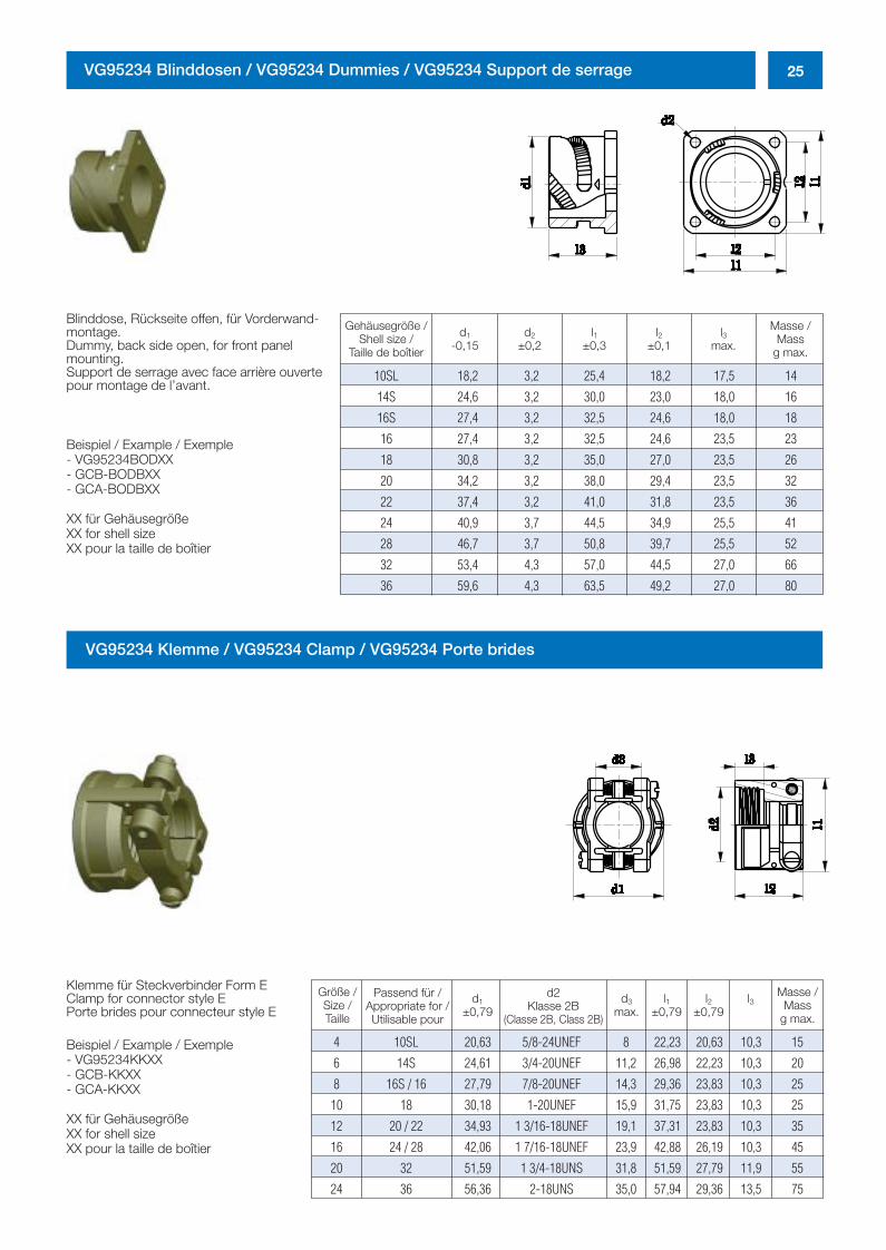
25VG95234 Blinddosen / VG95234 Dummies / VG95234 Support de serrage
Blinddose, Rückseite offen, für Vorderwand-montage.Dummy, back side open, for front panelmounting.Support de serrage avec face arrière ouvertepour montage de l’avant.
Beispiel / Example / Exemple - VG95234BODXX- GCB-BODBXX- GCA-BODBXX
XX für GehäusegrößeXX for shell sizeXX pour la taille de boîtier
VG95234 Klemme / VG95234 Clamp / VG95234 Porte brides
Gehäusegröße /Shell size /
Taille de boîtier
d1
-0,15d2
±0,2l1
±0,3l2
±0,1l3
max.
Masse /Mass
g max.
10SL 18,2 3,2 25,4 18,2 17,5 14
14S 24,6 3,2 30,0 23,0 18,0 16
16S 27,4 3,2 32,5 24,6 18,0 18
16 27,4 3,2 32,5 24,6 23,5 23
18 30,8 3,2 35,0 27,0 23,5 26
20 34,2 3,2 38,0 29,4 23,5 32
22 37,4 3,2 41,0 31,8 23,5 36
24 40,9 3,7 44,5 34,9 25,5 41
28 46,7 3,7 50,8 39,7 25,5 52
32 53,4 4,3 57,0 44,5 27,0 66
36 59,6 4,3 63,5 49,2 27,0 80
Größe /Size /Taille
Passend für /Appropriate for /Utilisable pour
d2Klasse 2B
(Classe 2B, Class 2B)
d1
±0,79l1
±0,79l2
±0,79l3d3
max.
Masse /Mass
g max.
4 10SL 20,63 5/8-24UNEF 8 22,23 20,63 10,3 15
6 14S 24,61 3/4-20UNEF 11,2 26,98 22,23 10,3 20
8 16S / 16 27,79 7/8-20UNEF 14,3 29,36 23,83 10,3 25
10 18 30,18 1-20UNEF 15,9 31,75 23,83 10,3 25
12 20 / 22 34,93 1 3/16-18UNEF 19,1 37,31 23,83 10,3 35
16 24 / 28 42,06 1 7/16-18UNEF 23,9 42,88 26,19 10,3 45
20 32 51,59 1 3/4-18UNS 31,8 51,59 27,79 11,9 55
24 36 56,36 2-18UNS 35,0 57,94 29,36 13,5 75
Klemme für Steckverbinder Form EClamp for connector style EPorte brides pour connecteur style E
Beispiel / Example / Exemple - VG95234KKXX- GCB-KKXX- GCA-KKXX
XX für GehäusegrößeXX for shell sizeXX pour la taille de boîtier
0298_ailb_kat.neu.411 04.03.2005 14:21 Uhr Seite 25
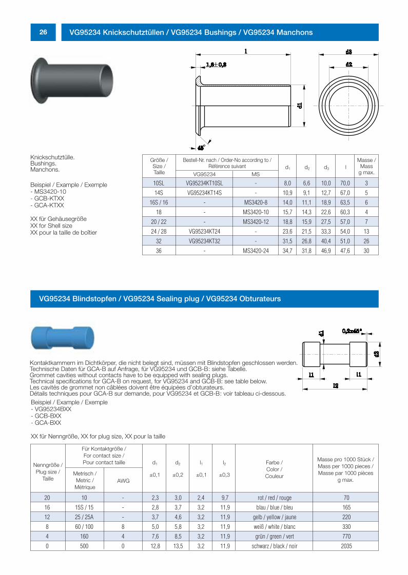
26 VG95234 Knickschutztüllen / VG95234 Bushings / VG95234 Manchons
Knickschutztülle.Bushings.Manchons.
Beispiel / Example / Exemple - MS3420-10- GCB-KTXX- GCA-KTXX
XX für GehäusegrößeXX for Shell sizeXX pour la taille de boîtier
Größe /Size /Taille
d1 d2 d3 lMasse /
Massg max.
10SL VG95234KT10SL - 8,0 6,6 10,0 70,0 3
14S VG95234KT14S - 10,9 9,1 12,7 67,0 5
16S / 16 - MS3420-8 14,0 11,1 18,9 63,5 6
18 - MS3420-10 15,7 14,3 22,6 60,3 4
20 / 22 - MS3420-12 18,8 15,9 27,5 57,0 7
24 / 28 VG95234KT24 - 23,6 21,5 33,3 54,0 13
32 VG95234KT32 - 31,5 26,8 40,4 51,0 26
36 - MS3420-24 34,7 31,8 46,9 47,6 30
Bestell-Nr. nach / Order-No according to /Référence suivant
VG95234 MS
Nenngröße /Plug size /
Taille
Für Kontaktgröße /For contact size /Pour contact taille
AWG
20 10 - 2,3 3,0 2,4 9,7 rot / red / rouge 70
16 15S / 15 - 2,8 3,7 3,2 11,9 blau / blue / bleu 165
12 25 / 25A - 3,7 4,6 3,2 11,9 gelb / yellow / jaune 220
8 60 / 100 8 5,0 5,8 3,2 11,9 weiß / white / blanc 330
4 160 4 7,6 8,5 3,2 11,9 grün / green / vert 770
0 500 0 12,8 13,5 3,2 11,9 schwarz / black / noir 2035
Metrisch /Metric /Métrique
Masse pro 1000 Stück /Mass per 1000 pieces /Masse par 1000 pièces
g max.
Farbe /Color /Couleur
d1
±0,1
d2
±0,2
l1
±0,1
l2
±0,3
VG95234 Blindstopfen / VG95234 Sealing plug / VG95234 Obturateurs
Kontaktkammern im Dichtkörper, die nicht belegt sind, müssen mit Blindstopfen geschlossen werden.Technische Daten für GCA-B auf Anfrage, für VG95234 und GCB-B: siehe Tabelle.Grommet cavities without contacts have to be equipped with sealing plugs.Technical specifications for GCA-B on request, for VG95234 and GCB-B: see table below.Les cavités de grommet non câblées doivent être équipées d’obturateurs. Détails techniques pour GCA-B sur demande, pour VG95234 et GCB-B: voir tableau ci-dessous.Beispiel / Example / Exemple - VG95234BXX- GCB-BXX- GCA-BXX
XX für Nenngröße, XX for plug size, XX pour la taille
0298_ailb_kat.neu.411 04.03.2005 14:21 Uhr Seite 26
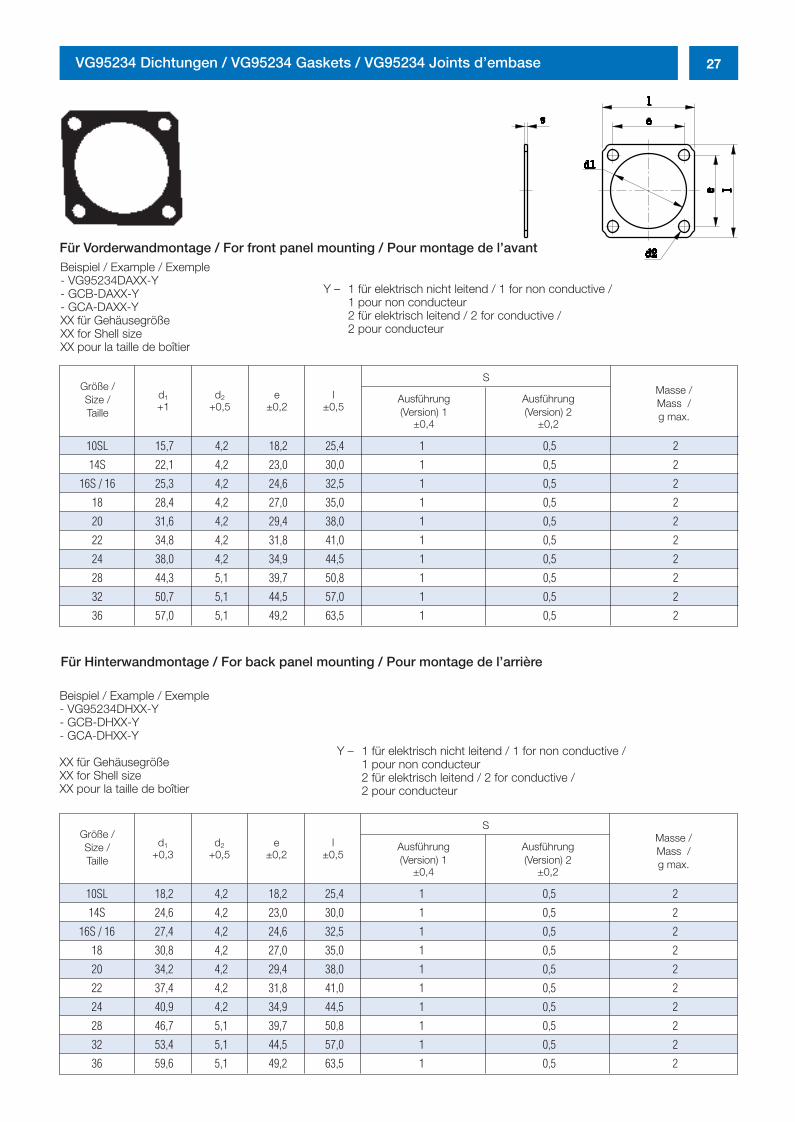
27VG95234 Dichtungen / VG95234 Gaskets / VG95234 Joints d’embase
Größe /Size /Taille
10SL 18,2 4,2 18,2 25,4 1 0,5 2
14S 24,6 4,2 23,0 30,0 1 0,5 2
16S / 16 27,4 4,2 24,6 32,5 1 0,5 2
18 30,8 4,2 27,0 35,0 1 0,5 2
20 34,2 4,2 29,4 38,0 1 0,5 2
22 37,4 4,2 31,8 41,0 1 0,5 2
24 40,9 4,2 34,9 44,5 1 0,5 2
28 46,7 5,1 39,7 50,8 1 0,5 2
32 53,4 5,1 44,5 57,0 1 0,5 2
36 59,6 5,1 49,2 63,5 1 0,5 2
Masse /Mass /g max.
Ausführung(Version) 2
±0,2
Ausführung(Version) 1
±0,4
d1
+0,3d2
+0,5e
±0,2l
±0,5
S
Beispiel / Example / Exemple - VG95234DAXX-Y- GCB-DAXX-Y- GCA-DAXX-YXX für GehäusegrößeXX for Shell sizeXX pour la taille de boîtier
Größe /Size /Taille
10SL 15,7 4,2 18,2 25,4 1 0,5 2
14S 22,1 4,2 23,0 30,0 1 0,5 2
16S / 16 25,3 4,2 24,6 32,5 1 0,5 2
18 28,4 4,2 27,0 35,0 1 0,5 2
20 31,6 4,2 29,4 38,0 1 0,5 2
22 34,8 4,2 31,8 41,0 1 0,5 2
24 38,0 4,2 34,9 44,5 1 0,5 2
28 44,3 5,1 39,7 50,8 1 0,5 2
32 50,7 5,1 44,5 57,0 1 0,5 2
36 57,0 5,1 49,2 63,5 1 0,5 2
Masse /Mass /g max.
Ausführung(Version) 2
±0,2
Ausführung(Version) 1
±0,4
d1
+1d2
+0,5e
±0,2l
±0,5
S
Beispiel / Example / Exemple - VG95234DHXX-Y- GCB-DHXX-Y- GCA-DHXX-Y
XX für GehäusegrößeXX for Shell sizeXX pour la taille de boîtier
Y – 1 für elektrisch nicht leitend / 1 for non conductive / 1 pour non conducteur2 für elektrisch leitend / 2 for conductive /2 pour conducteur
Y – 1 für elektrisch nicht leitend / 1 for non conductive / 1 pour non conducteur2 für elektrisch leitend / 2 for conductive / 2 pour conducteur
Für Hinterwandmontage / For back panel mounting / Pour montage de l’arrière
Für Vorderwandmontage / For front panel mounting / Pour montage de l’avant
0298_ailb_kat.neu.411 04.03.2005 14:21 Uhr Seite 27
28 GCB-B 3100 PG – PM / GCA-B 3100 PG – PM
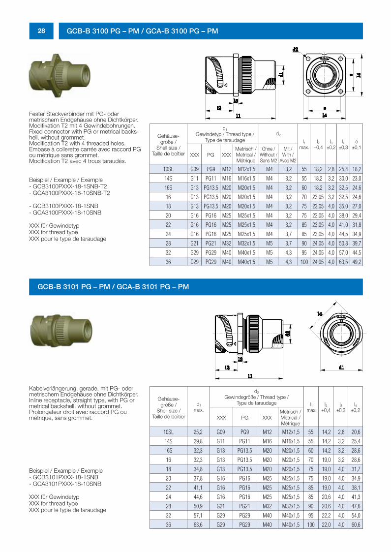
Fester Steckverbinder mit PG- oder metrischem Endgehäuse ohne Dichtkörper.Modifikation T2 mit 4 Gewindebohrungen.Fixed connector with PG or metrical backs-hell, without grommet.Modification T2 with 4 threaded holes.Embase à collerette carrée avec raccord PGou métrique sans grommet.Modification T2 avec 4 trous taraudés.
Beispiel / Example / Exemple - GCB3100PXXX-18-1SNB-T2- GCA3100PXXX-18-10SNB-T2
- GCB3100PXXX-18-1SNB- GCA3100PXXX-18-10SNB
XXX für GewindetypXXX for thread typeXXX pour le type de taraudage
Gehäuse-größe /
Shell size /Taille de boîtier
e±0,1
l1max.
l2+0,4
l3±0,2
l4±0,3
10SL G09 PG9 M12 M12x1,5 M4 3,2 55 18,2 2,8 25,4 18,2
14S G11 PG11 M16 M16x1,5 M4 3,2 55 18,2 3,2 30,0 23,0
16S G13 PG13,5 M20 M20x1,5 M4 3,2 60 18,2 3,2 32,5 24,6
16 G13 PG13,5 M20 M20x1,5 M4 3,2 70 23,05 3,2 32,5 24,6
18 G13 PG13,5 M20 M20x1,5 M4 3,2 75 23,05 4,0 35,0 27,0
20 G16 PG16 M25 M25x1,5 M4 3,2 75 23,05 4,0 38,0 29,4
22 G16 PG16 M25 M25x1,5 M4 3,2 85 23,05 4,0 41,0 31,8
24 G16 PG16 M25 M25x1,5 M4 3,7 85 23,05 4,0 44,5 34,9
28 G21 PG21 M32 M32x1,5 M5 3,7 90 24,05 4,0 50,8 39,7
32 G29 PG29 M40 M40x1,5 M5 4,3 95 24,05 4,0 57,0 44,5
36 G29 PG29 M40 M40x1,5 M5 4,3 100 24,05 4,0 63,5 49,2
d2
d1
Gewindetyp / Thread type /Type de taraudage
XXX PG XXXMetrisch /Metrical /Métrique
Ohne /Without /Sans M2
Mit /With /
Avec M2
GCB-B 3101 PG – PM / GCA-B 3101 PG – PM
Gehäuse-größe /
Shell size /Taille de boîtier
l1max.
l2+0,4
l3±0,2
l4±0,2
10SL 25,2 G09 PG9 M12 M12x1,5 55 14,2 2,8 20,6
14S 29,8 G11 PG11 M16 M16x1,5 55 14,2 3,2 25,4
16S 32,3 G13 PG13,5 M20 M20x1,5 60 14,2 3,2 28,6
16 32,3 G13 PG13,5 M20 M20x1,5 70 19,0 3,2 28,6
18 34,8 G13 PG13,5 M20 M20x1,5 75 19,0 4,0 31,7
20 37,8 G16 PG16 M25 M25x1,5 75 19,0 4,0 34,9
22 41,1 G16 PG16 M25 M25x1,5 85 19,0 4,0 38,1
24 44,6 G16 PG16 M25 M25x1,5 85 20,6 4,0 41,3
28 50,9 G21 PG21 M32 M32x1,5 90 20,6 4,0 47,6
32 57,1 G29 PG29 M40 M40x1,5 95 22,2 4,0 54,0
36 63,6 G29 PG29 M40 M40x1,5 100 22,0 4,0 60,6
d2
Gewindegröße / Thread type /Type de taraudage
XXX PG XXXMetrisch /Metrical /Métrique
d1
max.
Kabelverlängerung, gerade, mit PG- odermetrischem Endgehäuse ohne Dichtkörper.Inline receptacle, straight type, with PG ormetrical backshell, without grommet.Prolongateur droit avec raccord PG oumétrique, sans grommet.
Beispiel / Example / Exemple - GCB3101PXXX-18-1SNB- GCA3101PXXX-18-10SNB
XXX für GewindetypXXX for thread typeXXX pour le type de taraudage
0298_ailb_kat.neu.411 04.03.2005 14:21 Uhr Seite 28
29GCB-B 3106 PG – PM / GCA-B 3106 PG – PM
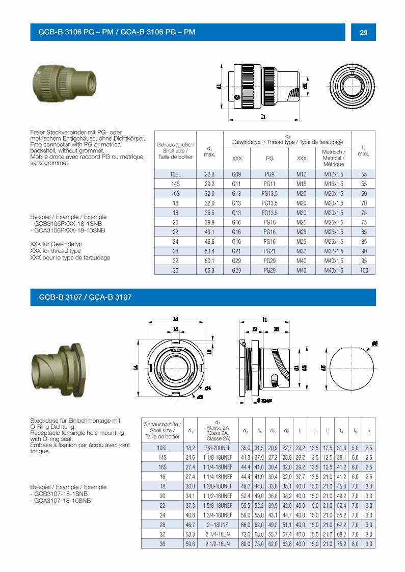
Freier Steckverbinder mit PG- oder metrischem Endgehäuse, ohne Dichtkörper.Free connector with PG or metrical backshell, without grommet.Mobile droite avec raccord PG ou métrique,sans grommet.
Beispiel / Example / Exemple - GCB3106PXXX-18-1SNB- GCA3106PXXX-18-10SNB
XXX für GewindetypXXX for thread typeXXX pour le type de taraudage
GCB-B 3107 / GCA-B 3107
Gehäusegröße /Shell size /
Taille de boîtier
d1
max.XXX XXXPG
10SL 22,8 G09 PG9 M12 M12x1,5 55
14S 29,2 G11 PG11 M16 M16x1,5 55
16S 32,0 G13 PG13,5 M20 M20x1,5 60
16 32,0 G13 PG13,5 M20 M20x1,5 70
18 36,5 G13 PG13,5 M20 M20x1,5 75
20 39,9 G16 PG16 M25 M25x1,5 75
22 43,1 G16 PG16 M25 M25x1,5 85
24 46,6 G16 PG16 M25 M25x1,5 85
28 53,4 G21 PG21 M32 M32x1,5 90
32 60,1 G29 PG29 M40 M40x1,5 95
36 66,3 G29 PG29 M40 M40x1,5 100
d2
Gewindetyp / Thread type / Type de taraudagel1
max.Metrisch /Metrical /Métrique
Gehäusegröße /Shell size /
Taille de boîtierd1
d2Klasse 2A(Class 2A,Classe 2A)
d3 d4 d5 d6 l1 l2 l3 l4 l5 l6
10SL 18,2 7/8-20UNEF 35,0 31,5 20,9 22,7 29,2 13,5 12,5 31,8 5,0 2,5
14S 24,6 1 1/8-18UNEF 41,3 37,9 27,2 28,8 29,2 13,5 12,5 38,1 6,0 2,5
16S 27,4 1 1/4-18UNEF 44,4 41,0 30,4 32,0 29,2 13,5 12,5 41,2 6,0 2,5
16 27,4 1 1/4-18UNEF 44,4 41,0 30,4 32,0 37,7 13,5 21,0 41,2 6,0 2,5
18 30,8 1 3/8-18UNEF 48,2 44,8 33,6 35,1 40,0 15,0 21,0 45,0 7,0 3,0
20 34,1 1 1/2-18UNEF 52,4 49,0 36,8 38,2 40,0 15,0 21,0 49,2 7,0 3,0
22 37,3 1 5/8-18UNEF 55,5 52,2 39,9 42,0 40,0 15,0 21,0 52,4 7,0 3,0
24 40,8 1 3/4-18UNEF 59,0 55,0 43,1 44,7 40,0 15,0 21,0 55,2 7,0 3,0
28 46,7 2 –18UNS 66,0 62,0 49,2 51,1 40,0 15,0 21,0 62,2 7,0 3,0
32 53,3 2 1/4-16UN 72,0 68,0 55,7 57,4 40,0 15,0 21,0 68,2 7,0 3,0
36 59,6 2 1/2-16UN 80,0 75,0 62,0 63,8 40,0 15,0 21,0 75,2 8,0 3,0
Steckdose für Einlochmontage mit O-Ring Dichtung.Receptacle for single hole mountingwith O-ring seal.Embase à fixation par écrou avec jointtorique.
Beispiel / Example / Exemple - GCB3107-18-1SNB- GCA3107-18-10SNB
0298_ailb_kat.neu.411 04.03.2005 14:21 Uhr Seite 29
30 VG95234 / GCB-B – Stiftkontakte / Pin contacts / Contacts mâles
Kontakgröße /Contact size /
Taille de contactMetrisch /MetricalMétrique
Amphenol versilbert /silver plated /
argenté
Amphenol vergoldet /gold plated /
doréAWG
Teile-Nummer / Part-Number /Réference
VG95234
d1
-0,05
d2
max.
d3 d4 d5 d6 d7
Kontakgröße /Contact size /
Taille de contactMetrisch /MetricalMétrique
Amphenol versilbert /silver plated /
argenté
Amphenol vergoldet /gold plated /
doréAWG
Teile-Nummer / Part-Number /Réference
VG95234
d8
±0,1
l1
±0,2
l2
±0,15
l3
±0,1
l4
±0,5
l5
min.
l6 l7
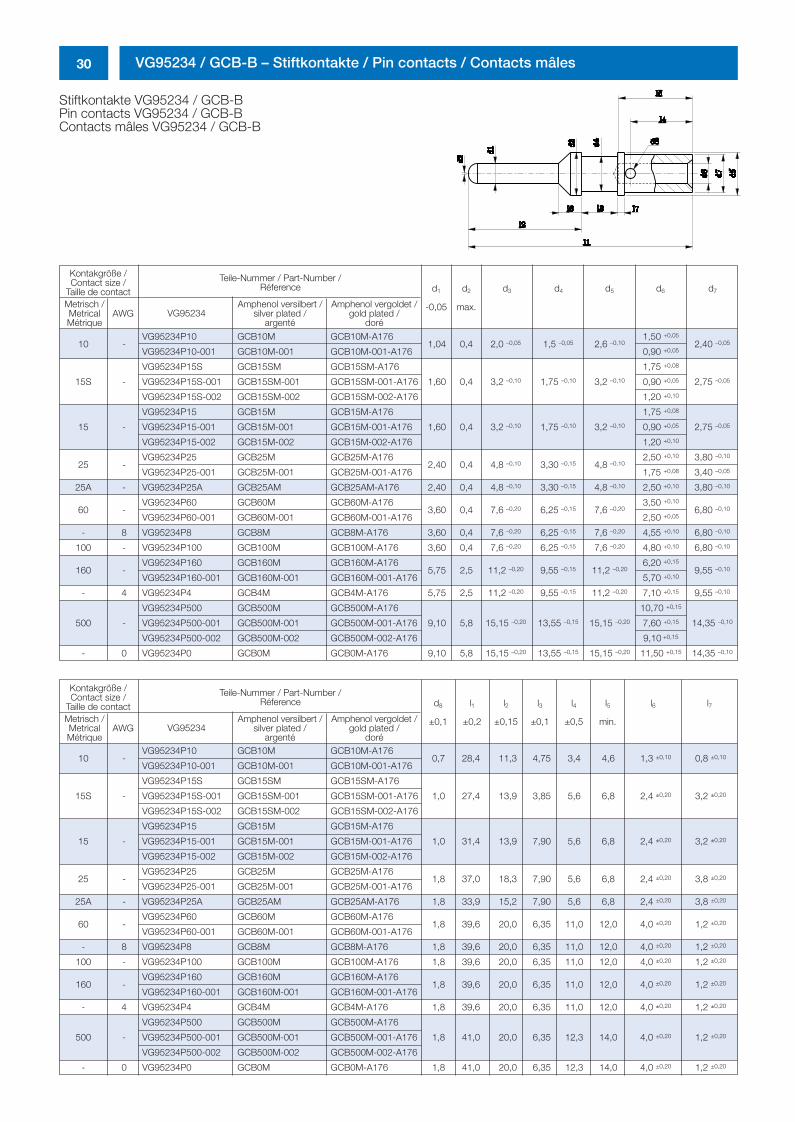
Stiftkontakte VG95234 / GCB-BPin contacts VG95234 / GCB-BContacts mâles VG95234 / GCB-B
10 -VG95234P10 GCB10M GCB10M-A176
1,04 0,4 2,0 –0,05 1,5 –0,05 2,6 –0,101,50 +0,05
2,40 –0,05
VG95234P10-001 GCB10M-001 GCB10M-001-A176 0,90 +0,05
15S -
VG95234P15S GCB15SM GCB15SM-A176
1,60 0,4 3,2 –0,10 1,75 –0,10 3,2 –0,10
1,75 +0,08
2,75 –0,05VG95234P15S-001 GCB15SM-001 GCB15SM-001-A176 0,90 +0,05
VG95234P15S-002 GCB15SM-002 GCB15SM-002-A176 1,20 +0,10
15 -
VG95234P15 GCB15M GCB15M-A176
1,60 0,4 3,2 –0,10 1,75 –0,10 3,2 –0,10
1,75 +0,08
2,75 –0,05VG95234P15-001 GCB15M-001 GCB15M-001-A176 0,90 +0,05
VG95234P15-002 GCB15M-002 GCB15M-002-A176 1,20 +0,10
25 -VG95234P25 GCB25M GCB25M-A176
2,40 0,4 4,8 –0,10 3,30 –0,15 4,8 –0,102,50 +0,10 3,80 –0,10
VG95234P25-001 GCB25M-001 GCB25M-001-A176 1,75 +0,08 3,40 –0,05
25A - VG95234P25A GCB25AM GCB25AM-A176 2,40 0,4 4,8 –0,10 3,30 –0,15 4,8 –0,10 2,50 +0,10 3,80 –0,10
60 -VG95234P60 GCB60M GCB60M-A176
3,60 0,4 7,6 –0,20 6,25 –0,15 7,6 –0,203,50 +0,10
6,80 –0,10
VG95234P60-001 GCB60M-001 GCB60M-001-A176 2,50 +0,05
- 8 VG95234P8 GCB8M GCB8M-A176 3,60 0,4 7,6 –0,20 6,25 –0,15 7,6 –0,20 4,55 +0,10 6,80 –0,10
100 - VG95234P100 GCB100M GCB100M-A176 3,60 0,4 7,6 –0,20 6,25 –0,15 7,6 –0,20 4,80 +0,10 6,80 –0,10
160 -VG95234P160 GCB160M GCB160M-A176
5,75 2,5 11,2 –0,20 9,55 –0,15 11,2 –0,206,20 +0,15
9,55 –0,10
VG95234P160-001 GCB160M-001 GCB160M-001-A176 5,70 +0,10
- 4 VG95234P4 GCB4M GCB4M-A176 5,75 2,5 11,2 –0,20 9,55 –0,15 11,2 –0,20 7,10 +0,15 9,55 –0,10
500 -
VG95234P500 GCB500M GCB500M-A176
9,10 5,8 15,15 –0,20 13,55 –0,15 15,15 –0,20
10,70 +0,15
14,35 –0,10VG95234P500-001 GCB500M-001 GCB500M-001-A176 7,60 +0,15
VG95234P500-002 GCB500M-002 GCB500M-002-A176 9,10 +0,15
- 0 VG95234P0 GCB0M GCB0M-A176 9,10 5,8 15,15 –0,20 13,55 –0,15 15,15 –0,20 11,50 +0,15 14,35 –0,10
10 -VG95234P10 GCB10M GCB10M-A176
0,7 28,4 11,3 4,75 3,4 4,6 1,3 ±0,10 0,8 ±0,10
VG95234P10-001 GCB10M-001 GCB10M-001-A176
15S -
VG95234P15S GCB15SM GCB15SM-A176
1,0 27,4 13,9 3,85 5,6 6,8 2,4 ±0,20 3,2 ±0,20VG95234P15S-001 GCB15SM-001 GCB15SM-001-A176
VG95234P15S-002 GCB15SM-002 GCB15SM-002-A176
15 -
VG95234P15 GCB15M GCB15M-A176
1,0 31,4 13,9 7,90 5,6 6,8 2,4 ±0,20 3,2 ±0,20VG95234P15-001 GCB15M-001 GCB15M-001-A176
VG95234P15-002 GCB15M-002 GCB15M-002-A176
25 -VG95234P25 GCB25M GCB25M-A176
1,8 37,0 18,3 7,90 5,6 6,8 2,4 ±0,20 3,8 ±0,20
VG95234P25-001 GCB25M-001 GCB25M-001-A176
25A - VG95234P25A GCB25AM GCB25AM-A176 1,8 33,9 15,2 7,90 5,6 6,8 2,4 ±0,20 3,8 ±0,20
60 -VG95234P60 GCB60M GCB60M-A176
1,8 39,6 20,0 6,35 11,0 12,0 4,0 ±0,20 1,2 ±0,20
VG95234P60-001 GCB60M-001 GCB60M-001-A176
- 8 VG95234P8 GCB8M GCB8M-A176 1,8 39,6 20,0 6,35 11,0 12,0 4,0 ±0,20 1,2 ±0,20
100 - VG95234P100 GCB100M GCB100M-A176 1,8 39,6 20,0 6,35 11,0 12,0 4,0 ±0,20 1,2 ±0,20
160 -VG95234P160 GCB160M GCB160M-A176
1,8 39,6 20,0 6,35 11,0 12,0 4,0 ±0,20 1,2 ±0,20
VG95234P160-001 GCB160M-001 GCB160M-001-A176
- 4 VG95234P4 GCB4M GCB4M-A176 1,8 39,6 20,0 6,35 11,0 12,0 4,0 ±0,20 1,2 ±0,20
500 -
VG95234P500 GCB500M GCB500M-A176
1,8 41,0 20,0 6,35 12,3 14,0 4,0 ±0,20 1,2 ±0,20VG95234P500-001 GCB500M-001 GCB500M-001-A176
VG95234P500-002 GCB500M-002 GCB500M-002-A176
- 0 VG95234P0 GCB0M GCB0M-A176 1,8 41,0 20,0 6,35 12,3 14,0 4,0 ±0,20 1,2 ±0,20
0298_ailb_kat.neu.411 04.03.2005 14:21 Uhr Seite 30
31VG95234 / GCB-B – Buchsenkontakte / Socket contacts / Contacts femelles
Kontakgröße /Contact size /
Taille de contactMetrisch /MetricalMétrique
Amphenol versilbert /silver plated /
argenté
Amphenol vergoldet /gold plated /
doréAWG
Teile-Nummer / Part-Number /Réference
VG95234
l2 l3
±0,1
l4
±0,5
l5
min.
l6
min.
l7 l8
±0,2
Kontakgröße /Contact size /
Taille de contactMetrisch /MetricalMétrique
Amphenol versilbert /silver plated /
argenté
Amphenol vergoldet /gold plated /
doréAWG
Teile-Nummer / Part-Number /Réference
VG95234
d1 d2 d3 d4 d5 d6 l1
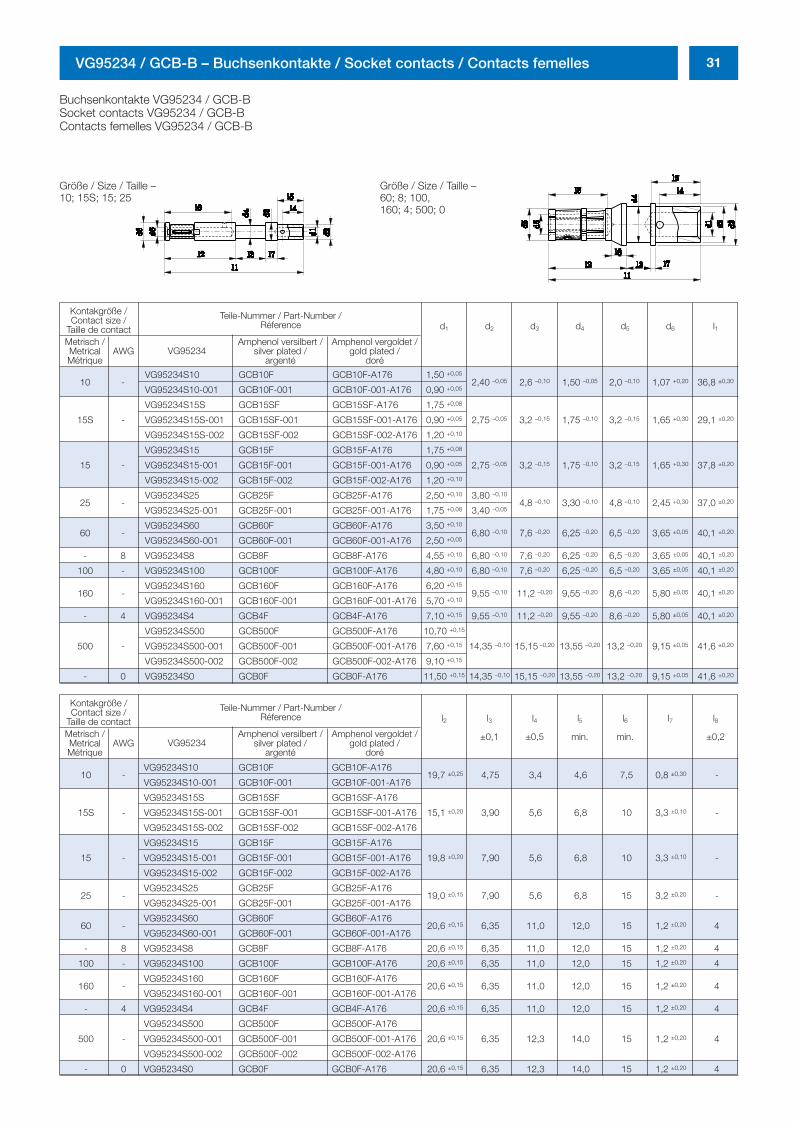
Buchsenkontakte VG95234 / GCB-BSocket contacts VG95234 / GCB-BContacts femelles VG95234 / GCB-B
Größe / Size / Taille –60; 8; 100,160; 4; 500; 0
Größe / Size / Taille –10; 15S; 15; 25
10 -VG95234S10 GCB10F GCB10F-A176 1,50 +0,05
2,40 –0,05 2,6 –0,10 1,50 –0,05 2,0 –0,10 1,07 +0,20 36,8 ±0,30
VG95234S10-001 GCB10F-001 GCB10F-001-A176 0,90 +0,05
15S -
VG95234S15S GCB15SF GCB15SF-A176 1,75 +0,08
2,75 –0,05 3,2 –0,15 1,75 –0,10 3,2 –0,15 1,65 +0,30 29,1 ±0,20VG95234S15S-001 GCB15SF-001 GCB15SF-001-A176 0,90 +0,05
VG95234S15S-002 GCB15SF-002 GCB15SF-002-A176 1,20 +0,10
15 -
VG95234S15 GCB15F GCB15F-A176 1,75 +0,08
2,75 –0,05 3,2 –0,15 1,75 –0,10 3,2 –0,15 1,65 +0,30 37,8 ±0,20VG95234S15-001 GCB15F-001 GCB15F-001-A176 0,90 +0,05
VG95234S15-002 GCB15F-002 GCB15F-002-A176 1,20 +0,10
25 -VG95234S25 GCB25F GCB25F-A176 2,50 +0,10 3,80 –0,10
4,8 –0,10 3,30 –0,10 4,8 –0,10 2,45 +0,30 37,0 ±0,20
VG95234S25-001 GCB25F-001 GCB25F-001-A176 1,75 +0,08 3,40 –0,05
60 -VG95234S60 GCB60F GCB60F-A176 3,50 +0,10
6,80 –0,10 7,6 –0,20 6,25 –0,20 6,5 –0,20 3,65 ±0,05 40,1 ±0,20
VG95234S60-001 GCB60F-001 GCB60F-001-A176 2,50 +0,05
- 8 VG95234S8 GCB8F GCB8F-A176 4,55 +0,10 6,80 –0,10 7,6 –0,20 6,25 –0,20 6,5 –0,20 3,65 ±0,05 40,1 ±0,20
100 - VG95234S100 GCB100F GCB100F-A176 4,80 +0,10 6,80 –0,10 7,6 –0,20 6,25 –0,20 6,5 –0,20 3,65 ±0,05 40,1 ±0,20
160 -VG95234S160 GCB160F GCB160F-A176 6,20 +0,15
9,55 –0,10 11,2 –0,20 9,55 –0,20 8,6 –0,20 5,80 ±0,05 40,1 ±0,20
VG95234S160-001 GCB160F-001 GCB160F-001-A176 5,70 +0,10
- 4 VG95234S4 GCB4F GCB4F-A176 7,10 +0,15 9,55 –0,10 11,2 –0,20 9,55 –0,20 8,6 –0,20 5,80 ±0,05 40,1 ±0,20
500 -
VG95234S500 GCB500F GCB500F-A176 10,70 +0,15
14,35 –0,10 15,15 –0,20 13,55 –0,20 13,2 –0,20 9,15 ±0,05 41,6 ±0,20VG95234S500-001 GCB500F-001 GCB500F-001-A176 7,60 +0,15
VG95234S500-002 GCB500F-002 GCB500F-002-A176 9,10 +0,15
- 0 VG95234S0 GCB0F GCB0F-A176 11,50 +0,15 14,35 –0,10 15,15 –0,20 13,55 –0,20 13,2 –0,20 9,15 ±0,05 41,6 ±0,20
10 -VG95234S10 GCB10F GCB10F-A176
19,7 ±0,25 4,75 3,4 4,6 7,5 0,8 ±0,30 -VG95234S10-001 GCB10F-001 GCB10F-001-A176
15S -
VG95234S15S GCB15SF GCB15SF-A176
15,1 ±0,20 3,90 5,6 6,8 10 3,3 ±0,10 -VG95234S15S-001 GCB15SF-001 GCB15SF-001-A176
VG95234S15S-002 GCB15SF-002 GCB15SF-002-A176
15 -
VG95234S15 GCB15F GCB15F-A176
19,8 ±0,20 7,90 5,6 6,8 10 3,3 ±0,10 -VG95234S15-001 GCB15F-001 GCB15F-001-A176
VG95234S15-002 GCB15F-002 GCB15F-002-A176
25 -VG95234S25 GCB25F GCB25F-A176
19,0 ±0,15 7,90 5,6 6,8 15 3,2 ±0,20 -VG95234S25-001 GCB25F-001 GCB25F-001-A176
60 -VG95234S60 GCB60F GCB60F-A176
20,6 ±0,15 6,35 11,0 12,0 15 1,2 ±0,20 4VG95234S60-001 GCB60F-001 GCB60F-001-A176
- 8 VG95234S8 GCB8F GCB8F-A176 20,6 ±0,15 6,35 11,0 12,0 15 1,2 ±0,20 4
100 - VG95234S100 GCB100F GCB100F-A176 20,6 ±0,15 6,35 11,0 12,0 15 1,2 ±0,20 4
160 -VG95234S160 GCB160F GCB160F-A176
20,6 ±0,15 6,35 11,0 12,0 15 1,2 ±0,20 4VG95234S160-001 GCB160F-001 GCB160F-001-A176
- 4 VG95234S4 GCB4F GCB4F-A176 20,6 ±0,15 6,35 11,0 12,0 15 1,2 ±0,20 4
500 -
VG95234S500 GCB500F GCB500F-A176
20,6 ±0,15 6,35 12,3 14,0 15 1,2 ±0,20 4VG95234S500-001 GCB500F-001 GCB500F-001-A176
VG95234S500-002 GCB500F-002 GCB500F-002-A176
- 0 VG95234S0 GCB0F GCB0F-A176 20,6 ±0,15 6,35 12,3 14,0 15 1,2 ±0,20 4
0298_ailb_kat.neu.411 04.03.2005 14:21 Uhr Seite 31
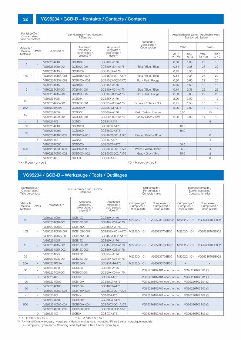
32 VG95234 / GCB-B – Kontakte / Contacts / Contacts
Kontakgröße /Contact size /
Taille de contact
Teile-Nummer / Part-Number /Réference
Anschließbarer Leiter / Applicable wire /Section admissible
Metrisch /MetricalMétrique
Amphenolversilbert /
silver plated /argenté (2)
Amphenolvergoldet /
gold plated /doré (2)
AWG VG95234 (1)
Farbcode /Color code /Code couleur mm2 AWG
von / for / de
bis / to / à
von / for / de
bis / to / à
10 -VG95234X10 GCB10X GCB10X-A176 - 0,50 1,00 20 18
VG95234X10-001 GCB10X-001 GCB10X-001-A176 Blau / Blue / Bleu 0,14 0,38 26 22
15S -
VG95234X15S GCB15SX GCB15SX-A176 - 0,75 1,50 18 16
VG95234X15S-001 GCB15SX-001 GCB15SX-001-A176 Blau / Blue / Bleu 0,14 0,38 26 22
VG95234X15S-002 GCB15SX-002 GCB15SX-002-A176 Rot / Red / Rouge 0,30 0,60 22 20
15 -
VG95234X15 GCB15X GCB15X-A176 - 0,75 1,50 18 16
VG95234X15-001 GCB15X-001 GCB15X-001-A176 Blau / Blue / Bleu 0,14 0,38 26 22
VG95234X15-002 GCB15X-002 GCB15X-002-A176 Rot / Red / Rouge 0,30 0,60 22 20
25 -VG95234X25 GCB25X GCB25X-A176 - 2,00 3,00 14 12
VG95234X25-001 GCB25X-001 GCB25X-001-A176 Schwarz / Black / Noir 0,75 1,50 18 16
25A - VG95234P25A GCB25AM GCB25AM-A176 - 2,00 3,00 14 12
60 -VG95234X60 GCB60X GCB60X-A176 Gelb / Yellow / Jaune 6,00 10
VG95234X60-001 GCB60X-001 GCB60X-001-A176 Grün / Green / Vert 2,00 3,00 14 12
- 8 VG95234X8 GCB8X GCB8X-A176 - - 8
100 - VG95234X100 GCB100X GCB100X-A176 - 10,0 -
160 -VG95234X160 GCB160X GCB160X-A176 - 16,0 -
VG95234X160-001 GCB160X-001 GCB160X-001-A176 Braun / Braun / Brun - 6
- 4 VG95234X4 GCB4X GCB4X-A176 - - 4
500 -
VG95234X500 GCB500X GCB500X-A176 - 50,0 -
VG95234X500-001 GCB500X-001 GCB500X-001-A176 Weiss / White / Blanc 25,0 4
VG95234X500-002 GCB500X-002 GCB500X-002-A176 Grau / Grey / Gris 35,0 2
- 0 VG95234X0 GCB0X GCB0X-A176 - - 0(1) X – P oder / or / ou S (2) X – M oder / or / ou F
(1) X – P oder / or / ou S (2) X – M oder / or / ou F(3) A – Hand-Crimpwerkzeug, hydraulisch / Hand crimping tools, hydraulic / Pince à sertir hydraulique manuelle
B – Crimpkopf, hydraulisch / Crimping head, hydraulic / Tête à sertir hydraulique
VG95234 / GCB-B – Werkzeuge / Tools / Outillages
Kontakgröße /Contact size /
Taille de contact
Teile-Nummer / Part-NumberRéférence
Stiftkontakte / Pin contacts /
Contacts mâles
Buchsenkontakte / Socket contacts /Contacts femelles
MetrischMetricalMétrique
AWG VG95234 (1)Amphenolversilbert /
silver plated /argenté (2)
Amphenolvergoldet /
gold plated /doré (2)
Crimpzange /Crimp tool /Pince à sertir
Crimpeinsatz /Crimp insert /Insert à sertir
Crimpzange /Crimp tool /Pince à sertir
Crimpeinsatz /Crimp insert /Insert à sertir
10 -VG95234X10 GCB10X GCB10X-A176
M22520/1-01 VG95236T03B002 M22520/1-01 VG95236T03B002VG95234X10-001 GCB10X-001 GCB10X-001-A176
15S -
VG95234X15S GCB15SX GCB15SX-A176
M22520/1-01 VG95236T03B001 M22520/1-01 VG95236T03B002VG95234X15S-001 GCB15SX-001 GCB15SX-001-A176
VG95234X15S-002 GCB15SX-002 GCB15SX-002-A176
15 -
VG95234X15 GCB15X GCB15X-A176
M22520/1-01 VG95236T03B001 M22520/1-01 VG95236T03B002VG95234X15-001 GCB15X-001 GCB15X-001-A176
VG95234X15-002 GCB15X-002 GCB15X-002-A176
25 -VG95234X25 GCB25X GCB25X-A176
M22520/1-01 VG95236T03B001 M22520/1-01 VG95236T03B002VG95234X25-001 GCB25X-001 GCB25X-001-A176
25A - VG95234P25A GCB25AM GCB25AM-A176 M22520/1-01 VG95236T03B001 - -
60 -VG95234X60 GCB60X GCB60X-A176
VG95236T02A01 oder / or / ou VG95236T02B01 (3)VG95234X60-001 GCB60X-001 GCB60X-001-A176
- 8 VG95234X8 GCB8X GCB8X-A176 VG95236T02A01 oder / or / ou VG95236T02B01 (3)
100 - VG95234X100 GCB100X GCB100X-A176 VG95236T02A01 oder / or / ou VG95236T02B01 (3)
160 -VG95234X160 GCB160X GCB160X-A176
VG95236T02A02 oder / or / ou VG95236T02B02 (3)VG95234X160-001 GCB160X-001 GCB160X-001-A176
- 4 VG95234X4 GCB4X GCB4X-A176 VG95236T02A02 oder / or / ou VG95236T02B02 (3)
500 -
VG95234X500 GCB500X GCB500X-A176
VG95236T02A03 oder / or / ou VG95236T02B03 (3)VG95234X500-001 GCB500X-001 GCB500X-001-A176
VG95234X500-002 GCB500X-002 GCB500X-002-A176
- 0 VG95234X0 GCB0X GCB0X-A176 VG95236T02A03 oder / or / ou VG95236T02B03 (3)
0298_ailb_kat.neu.411 04.03.2005 14:21 Uhr Seite 32
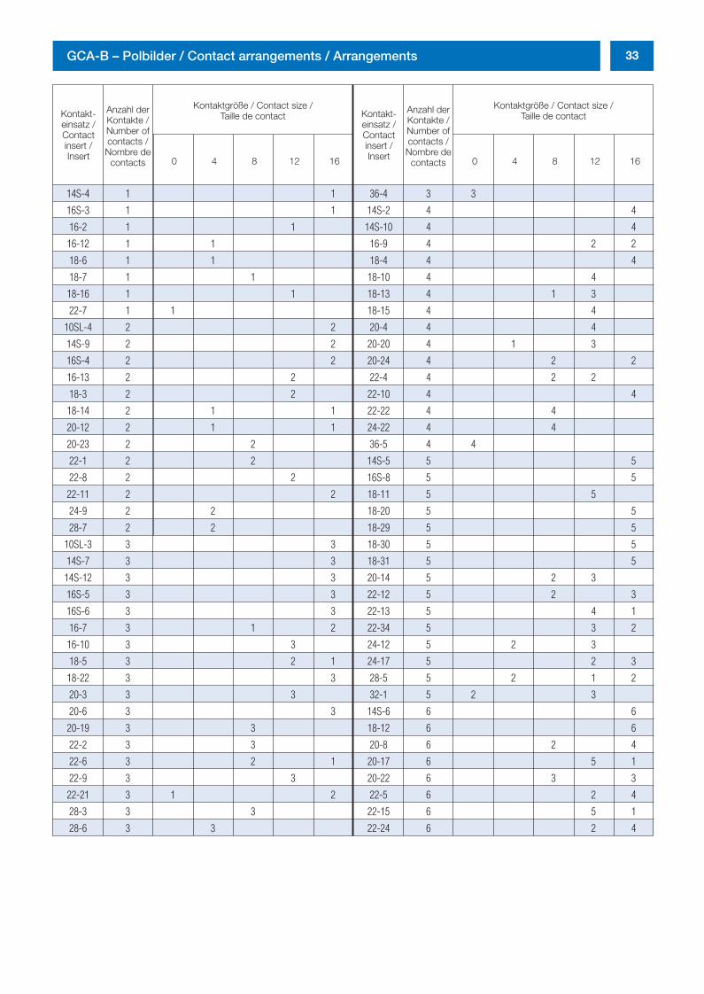
33GCA-B – Polbilder / Contact arrangements / Arrangements
Kontakt-einsatz /Contactinsert /Insert
Anzahl derKontakte /Number ofcontacts /Nombre de
contacts
Kontaktgröße / Contact size /Taille de contact
0 4 8 12 16 0 4 8 12 16
Kontakt-einsatz /Contactinsert /Insert
Anzahl derKontakte /Number ofcontacts /Nombre de
contacts
Kontaktgröße / Contact size /Taille de contact
14S-4 1 1 36-4 3 3
16S-3 1 1 14S-2 4 4
16-2 1 1 14S-10 4 4
16-12 1 1 16-9 4 2 2
18-6 1 1 18-4 4 4
18-7 1 1 18-10 4 4
18-16 1 1 18-13 4 1 3
22-7 1 1 18-15 4 4
10SL-4 2 2 20-4 4 4
14S-9 2 2 20-20 4 1 3
16S-4 2 2 20-24 4 2 2
16-13 2 2 22-4 4 2 2
18-3 2 2 22-10 4 4
18-14 2 1 1 22-22 4 4
20-12 2 1 1 24-22 4 4
20-23 2 2 36-5 4 4
22-1 2 2 14S-5 5 5
22-8 2 2 16S-8 5 5
22-11 2 2 18-11 5 5
24-9 2 2 18-20 5 5
28-7 2 2 18-29 5 5
10SL-3 3 3 18-30 5 5
14S-7 3 3 18-31 5 5
14S-12 3 3 20-14 5 2 3
16S-5 3 3 22-12 5 2 3
16S-6 3 3 22-13 5 4 1
16-7 3 1 2 22-34 5 3 2
16-10 3 3 24-12 5 2 3
18-5 3 2 1 24-17 5 2 3
18-22 3 3 28-5 5 2 1 2
20-3 3 3 32-1 5 2 3
20-6 3 3 14S-6 6 6
20-19 3 3 18-12 6 6
22-2 3 3 20-8 6 2 4
22-6 3 2 1 20-17 6 5 1
22-9 3 3 20-22 6 3 3
22-21 3 1 2 22-5 6 2 4
28-3 3 3 22-15 6 5 1
28-6 3 3 22-24 6 2 4
0298_ailb_kat.neu.411 04.03.2005 14:21 Uhr Seite 33
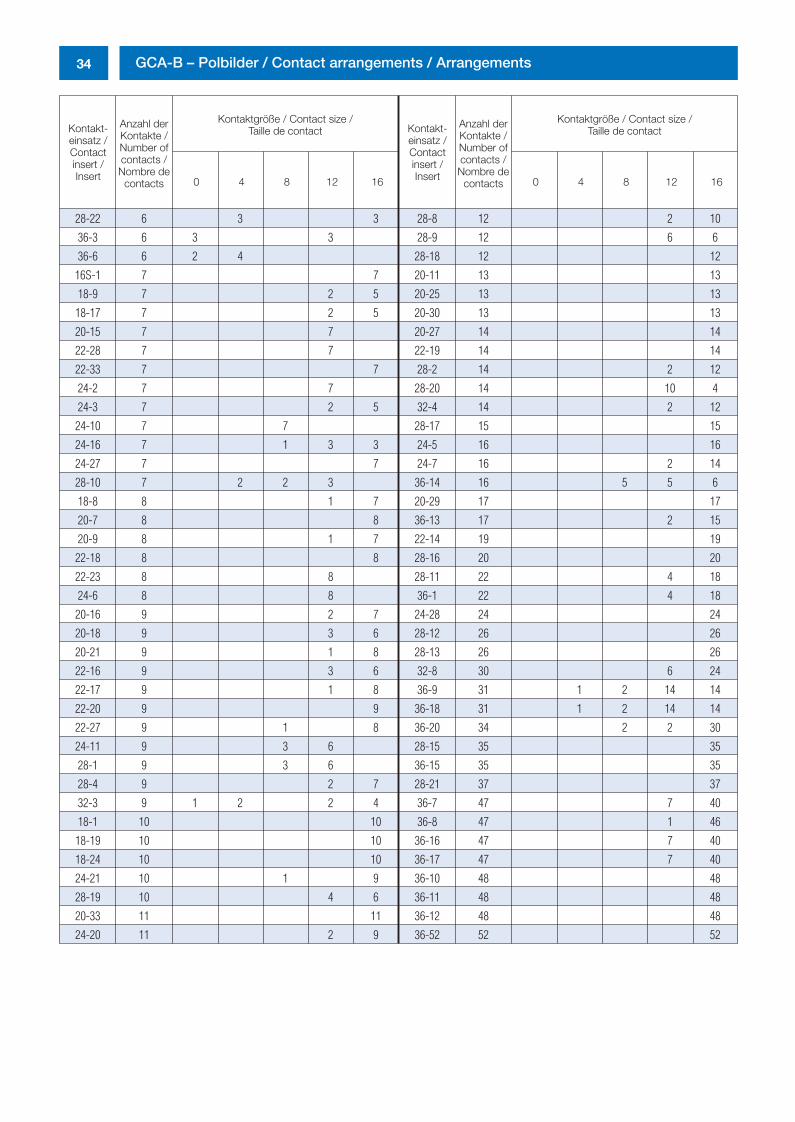
34 GCA-B – Polbilder / Contact arrangements / Arrangements
Kontakt-einsatz /Contactinsert /Insert
Anzahl derKontakte /Number ofcontacts /Nombre de
contacts
Kontaktgröße / Contact size /Taille de contact
0 4 8 12 16 0 4 8 12 16
Kontakt-einsatz /Contactinsert /Insert
Anzahl derKontakte /Number ofcontacts /Nombre de
contacts
Kontaktgröße / Contact size /Taille de contact
28-22 6 3 3 28-8 12 2 10
36-3 6 3 3 28-9 12 6 6
36-6 6 2 4 28-18 12 12
16S-1 7 7 20-11 13 13
18-9 7 2 5 20-25 13 13
18-17 7 2 5 20-30 13 13
20-15 7 7 20-27 14 14
22-28 7 7 22-19 14 14
22-33 7 7 28-2 14 2 12
24-2 7 7 28-20 14 10 4
24-3 7 2 5 32-4 14 2 12
24-10 7 7 28-17 15 15
24-16 7 1 3 3 24-5 16 16
24-27 7 7 24-7 16 2 14
28-10 7 2 2 3 36-14 16 5 5 6
18-8 8 1 7 20-29 17 17
20-7 8 8 36-13 17 2 15
20-9 8 1 7 22-14 19 19
22-18 8 8 28-16 20 20
22-23 8 8 28-11 22 4 18
24-6 8 8 36-1 22 4 18
20-16 9 2 7 24-28 24 24
20-18 9 3 6 28-12 26 26
20-21 9 1 8 28-13 26 26
22-16 9 3 6 32-8 30 6 24
22-17 9 1 8 36-9 31 1 2 14 14
22-20 9 9 36-18 31 1 2 14 14
22-27 9 1 8 36-20 34 2 2 30
24-11 9 3 6 28-15 35 35
28-1 9 3 6 36-15 35 35
28-4 9 2 7 28-21 37 37
32-3 9 1 2 2 4 36-7 47 7 40
18-1 10 10 36-8 47 1 46
18-19 10 10 36-16 47 7 40
18-24 10 10 36-17 47 7 40
24-21 10 1 9 36-10 48 48
28-19 10 4 6 36-11 48 48
20-33 11 11 36-12 48 48
24-20 11 2 9 36-52 52 52
0298_ailb_kat.neu.411 04.03.2005 14:21 Uhr Seite 34
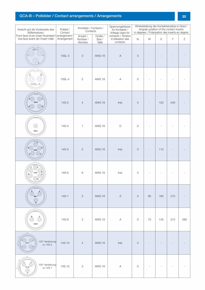
35GCA-B – Polbilder / Contact arrangements / Arrangements
Ansicht auf die Vorderseite desStifteinsatzes/
Front face of pin insert illustrated/Vue face avant de l’insert mâle
Polbild /Contact
arrangement/Arrangement
Kontakte / Contacts /Contacts
Spannungsklassefür Kontakte /
Voltage class forcontacts / Tension
d’utilisation descontacts
Winkelstellung der Kontakteinsätze in Grad /Angular position of the contact inserts
in degrees / Polarisation des inserts en degrésAnzahl /
Number /Nombre
Größe /Size /Taille
N W X Y Z
10SL-3 3 AWG 16 A 0 - - - -
10SL-4 2 AWG 16 A 0 - - - -
14S-2 4 AWG 16 Inst. 0 - 120 240 -
14S-4 1 AWG 16 D 0 - - - -
14S-5 5 AWG 16 Inst. 0 - 110 - -
14S-6 6 AWG 16 Inst. 0 - - - -
14S-7 3 AWG 16 A 0 90 180 270 -
14S-9 2 AWG 16 A 0 70 145 215 290
14S-10 4 AWG 16 Inst. 0 - - - -
14S-12 3 AWG 16 A 0 - - - -
100° Verdrehungzu 14S-2
100° Verdrehungzu 14S-7
0298_ailb_kat.neu.411 04.03.2005 14:21 Uhr Seite 35
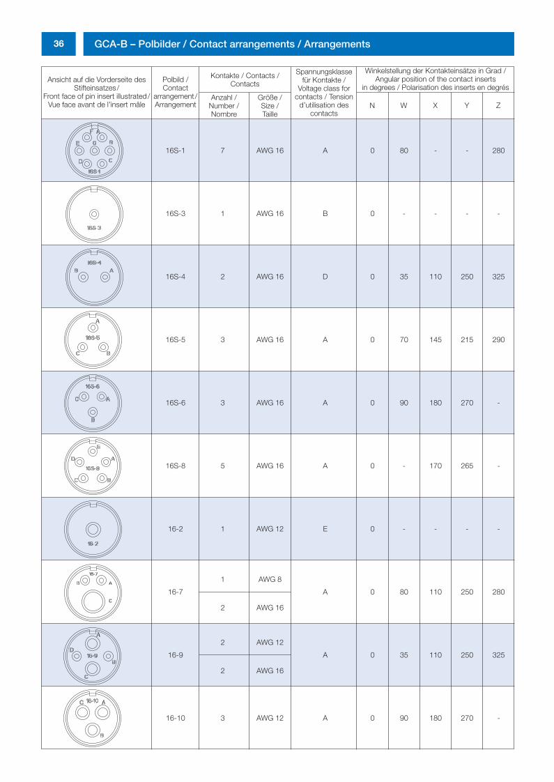
36 GCA-B – Polbilder / Contact arrangements / Arrangements
Ansicht auf die Vorderseite desStifteinsatzes/
Front face of pin insert illustrated/Vue face avant de l’insert mâle
Polbild /Contact
arrangement/Arrangement
Kontakte / Contacts /Contacts
Spannungsklassefür Kontakte /
Voltage class forcontacts / Tension
d’utilisation descontacts
Winkelstellung der Kontakteinsätze in Grad /Angular position of the contact inserts
in degrees / Polarisation des inserts en degrésAnzahl /
Number /Nombre
Größe /Size /Taille
N W X Y Z
16S-1 7 AWG 16 A 0 80 - - 280
16S-3 1 AWG 16 B 0 - - - -
16S-4 2 AWG 16 D 0 35 110 250 325
16S-5 3 AWG 16 A 0 70 145 215 290
16S-6 3 AWG 16 A 0 90 180 270 -
16S-8 5 AWG 16 A 0 - 170 265 -
16-2 1 AWG 12 E 0 - - - -
16-7
1 AWG 8
A 0 80 110 250 280
2 AWG 16
16-9
2 AWG 12
A 0 35 110 250 325
2 AWG 16
16-10 3 AWG 12 A 0 90 180 270 -
0298_ailb_kat.neu.411 04.03.2005 14:21 Uhr Seite 36
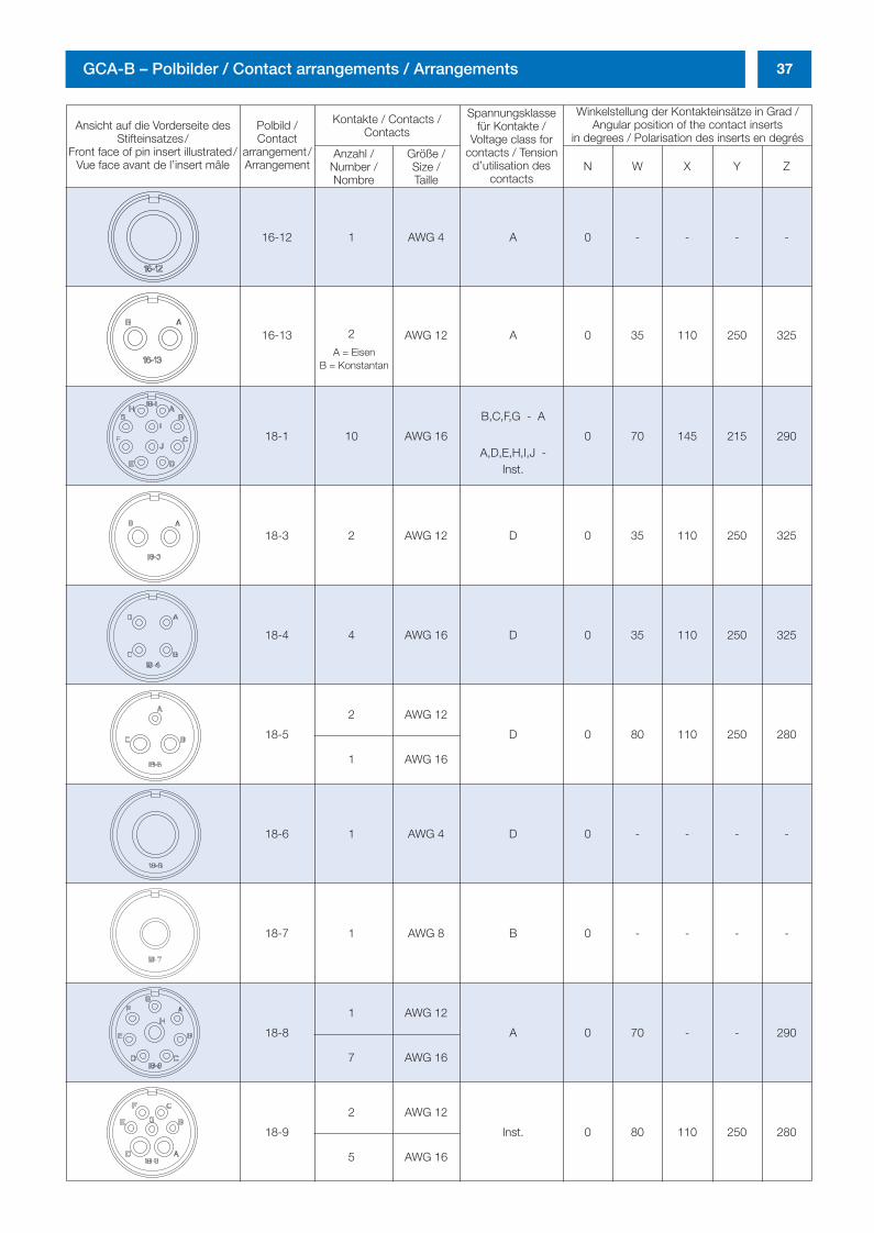
37GCA-B – Polbilder / Contact arrangements / Arrangements
Ansicht auf die Vorderseite desStifteinsatzes/
Front face of pin insert illustrated/Vue face avant de l’insert mâle
Polbild /Contact
arrangement/Arrangement
Kontakte / Contacts /Contacts
Spannungsklassefür Kontakte /
Voltage class forcontacts / Tension
d’utilisation descontacts
Winkelstellung der Kontakteinsätze in Grad /Angular position of the contact inserts
in degrees / Polarisation des inserts en degrésAnzahl /
Number /Nombre
Größe /Size /Taille
N W X Y Z
16-12 1 AWG 4 A 0 - - - -
16-13 2 AWG 12 A 0 35 110 250 325
18-1 10 AWG 16
B,C,F,G - A
0 70 145 215 290A,D,E,H,I,J -
Inst.
18-3 2 AWG 12 D 0 35 110 250 325
18-4 4 AWG 16 D 0 35 110 250 325
18-5
2 AWG 12
D 0 80 110 250 280
1 AWG 16
18-6 1 AWG 4 D 0 - - - -
18-7 1 AWG 8 B 0 - - - -
18-8
1 AWG 12
A 0 70 - - 290
7 AWG 16
18-9
2 AWG 12
Inst. 0 80 110 250 280
5 AWG 16
A = EisenB = Konstantan
0298_ailb_kat.neu.411 04.03.2005 14:21 Uhr Seite 37
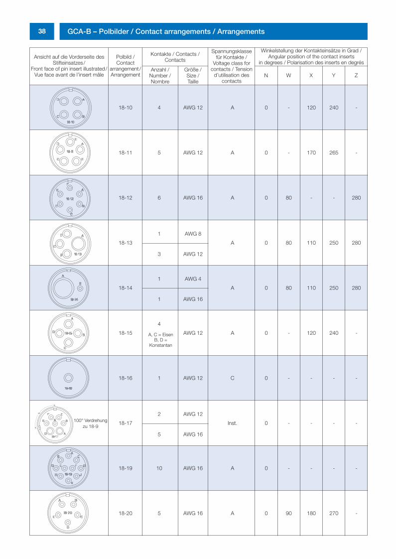
38 GCA-B – Polbilder / Contact arrangements / Arrangements
Ansicht auf die Vorderseite desStifteinsatzes/
Front face of pin insert illustrated/Vue face avant de l’insert mâle
Polbild /Contact
arrangement/Arrangement
Kontakte / Contacts /Contacts
Spannungsklassefür Kontakte /
Voltage class forcontacts / Tension
d’utilisation descontacts
Winkelstellung der Kontakteinsätze in Grad /Angular position of the contact inserts
in degrees / Polarisation des inserts en degrésAnzahl /
Number /Nombre
Größe /Size /Taille
N W X Y Z
18-10 4 AWG 12 A 0 - 120 240 -
18-11 5 AWG 12 A 0 - 170 265 -
18-12 6 AWG 16 A 0 80 - - 280
18-13
1 AWG 8
A 0 80 110 250 280
3 AWG 12
18-14
1 AWG 4
A 0 80 110 250 280
1 AWG 16
18-15
4
AWG 12 A 0 - 120 240 -
18-16 1 AWG 12 C 0 - - - -
18-17
2 AWG 12
Inst. 0 - - - -
5 AWG 16
18-19 10 AWG 16 A 0 - - - -
18-20 5 AWG 16 A 0 90 180 270 -
A, C = EisenB, D =
Konstantan
100° Verdrehungzu 18-9
0298_ailb_kat.neu.411 04.03.2005 14:21 Uhr Seite 38
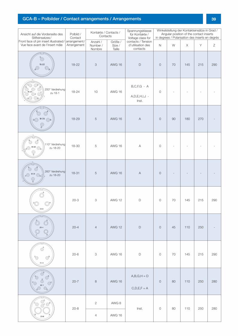
39GCA-B – Polbilder / Contact arrangements / Arrangements
Ansicht auf die Vorderseite desStifteinsatzes/
Front face of pin insert illustrated/Vue face avant de l’insert mâle
Polbild /Contact
arrangement/Arrangement
Kontakte / Contacts /Contacts
Spannungsklassefür Kontakte /
Voltage class forcontacts / Tension
d’utilisation descontacts
Winkelstellung der Kontakteinsätze in Grad /Angular position of the contact inserts
in degrees / Polarisation des inserts en degrésAnzahl /
Number /Nombre
Größe /Size /Taille
N W X Y Z
18-22 3 AWG 16 D 0 70 145 215 290
18-24 10 AWG 16
B,C,F,G - A
0 - - - -A,D,E,H,I,J -
Inst.
18-29 5 AWG 16 A 0 90 180 270 -
18-30 5 AWG 16 A 0 - - - -
18-31 5 AWG 16 A 0 - - - -
20-3 3 AWG 12 D 0 70 145 215 290
20-4 4 AWG 12 D 0 45 110 250 -
20-6 3 AWG 16 D 0 70 145 215 290
20-7 8 AWG 16
A,B,G,H = D
0 80 110 250 280
C,D,E,F = A
20-8
2 AWG 8
Inst. 0 80 110 250 280
4 AWG 16
250° Verdrehungzu 18-1
110° Verdrehungzu 18-20
260° Verdrehungzu 18-20
0298_ailb_kat.neu.411 04.03.2005 14:21 Uhr Seite 39

40 GCA-B – Polbilder / Contact arrangements / Arrangements
Ansicht auf die Vorderseite desStifteinsatzes/
Front face of pin insert illustrated/Vue face avant de l’insert mâle
Polbild /Contact
arrangement/Arrangement
Kontakte / Contacts /Contacts
Spannungsklassefür Kontakte /
Voltage class forcontacts / Tension
d’utilisation descontacts
Winkelstellung der Kontakteinsätze in Grad /Angular position of the contact inserts
in degrees / Polarisation des inserts en degrésAnzahl /
Number /Nombre
Größe /Size /Taille
N W X Y Z
20-9
1 AWG 12 H = D
0 80 110 250 280
7 AWG 16 A,B,C,D,E,F,G = A
20-11 13 AWG 16 Inst. 0 - - - -
20-12
1 AWG 4
A 0 80 110 250 280
1 AWG 16
20-14
2 AWG 8
A 0 80 110 250 280
3 AWG 12
20-15 7 AWG 12 A 0 80 - - 280
20-16
2 AWG 12
A 0 80 110 250 280
7 AWG 16
20-17
5 AWG 12
A 0 90 180 270 -
1 AWG 16
20-18
3 AWG 12
A 0 35 110 250 325
6 AWG 16
20-19 3 AWG 8 A 0 90 180 270 -
20-20
1 AWG 4
A 0 80 110 250 280
3 AWG 12
0298_ailb_kat.neu.411 04.03.2005 14:21 Uhr Seite 40
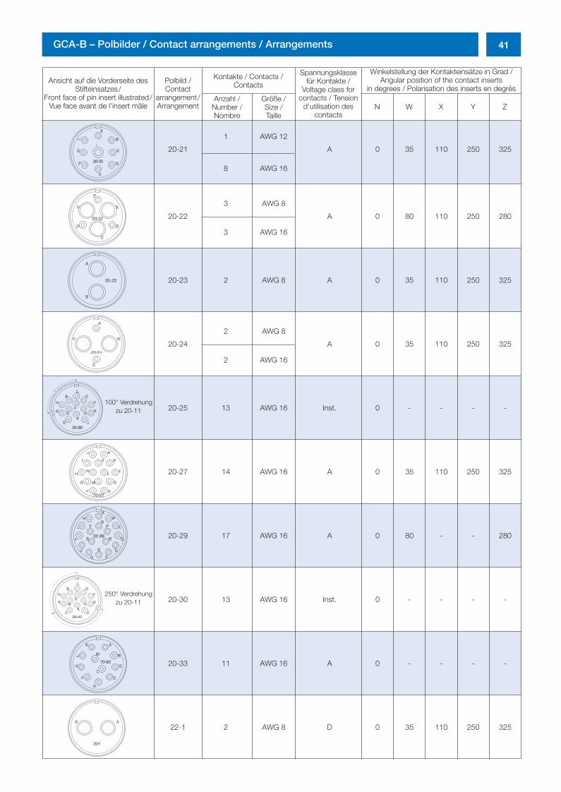
41GCA-B – Polbilder / Contact arrangements / Arrangements
Ansicht auf die Vorderseite desStifteinsatzes/
Front face of pin insert illustrated/Vue face avant de l’insert mâle
Polbild /Contact
arrangement/Arrangement
Kontakte / Contacts /Contacts
Spannungsklassefür Kontakte /
Voltage class forcontacts / Tension
d’utilisation descontacts
Winkelstellung der Kontakteinsätze in Grad /Angular position of the contact inserts
in degrees / Polarisation des inserts en degrésAnzahl /
Number /Nombre
Größe /Size /Taille
N W X Y Z
20-21
1 AWG 12
A 0 35 110 250 325
8 AWG 16
20-22
3 AWG 8
A 0 80 110 250 280
3 AWG 16
20-23 2 AWG 8 A 0 35 110 250 325
20-24
2 AWG 8
A 0 35 110 250 325
2 AWG 16
20-25 13 AWG 16 Inst. 0 - - - -
20-27 14 AWG 16 A 0 35 110 250 325
20-29 17 AWG 16 A 0 80 - - 280
20-30 13 AWG 16 Inst. 0 - - - -
20-33 11 AWG 16 A 0 - - - -
22-1 2 AWG 8 D 0 35 110 250 325
100° Verdrehungzu 20-11
250° Verdrehungzu 20-11
0298_ailb_kat.neu.411 04.03.2005 14:21 Uhr Seite 41
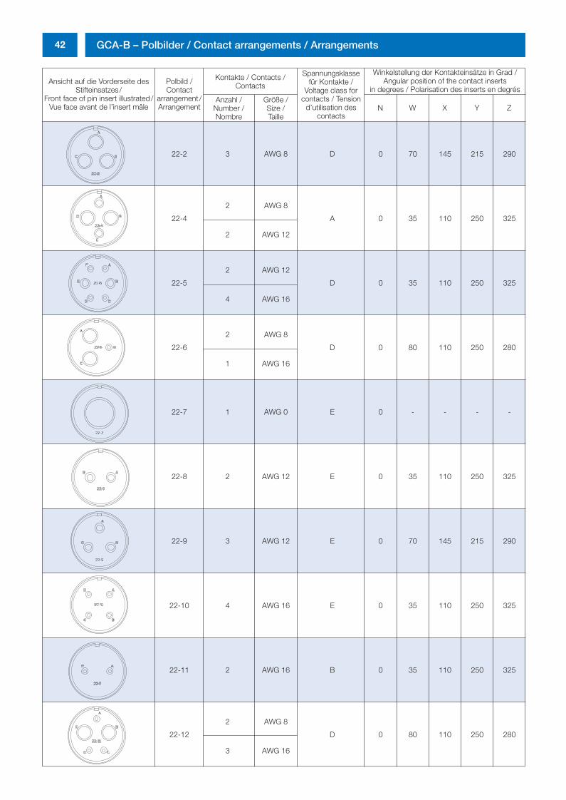
42 GCA-B – Polbilder / Contact arrangements / Arrangements
Ansicht auf die Vorderseite desStifteinsatzes/
Front face of pin insert illustrated/Vue face avant de l’insert mâle
Polbild /Contact
arrangement/Arrangement
Kontakte / Contacts /Contacts
Spannungsklassefür Kontakte /
Voltage class forcontacts / Tension
d’utilisation descontacts
Winkelstellung der Kontakteinsätze in Grad /Angular position of the contact inserts
in degrees / Polarisation des inserts en degrésAnzahl /
Number /Nombre
Größe /Size /Taille
N W X Y Z
22-2 3 AWG 8 D 0 70 145 215 290
22-4
2 AWG 8
A 0 35 110 250 325
2 AWG 12
22-5
2 AWG 12
D 0 35 110 250 325
4 AWG 16
22-6
2 AWG 8
D 0 80 110 250 280
1 AWG 16
22-7 1 AWG 0 E 0 - - - -
22-8 2 AWG 12 E 0 35 110 250 325
22-9 3 AWG 12 E 0 70 145 215 290
22-10 4 AWG 16 E 0 35 110 250 325
22-11 2 AWG 16 B 0 35 110 250 325
22-12
2 AWG 8
D 0 80 110 250 280
3 AWG 16
0298_ailb_kat.neu.411 04.03.2005 14:21 Uhr Seite 42
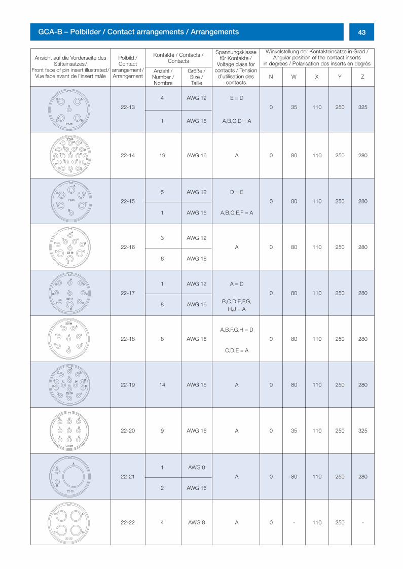
43GCA-B – Polbilder / Contact arrangements / Arrangements
Ansicht auf die Vorderseite desStifteinsatzes/
Front face of pin insert illustrated/Vue face avant de l’insert mâle
Polbild /Contact
arrangement/Arrangement
Kontakte / Contacts /Contacts
Spannungsklassefür Kontakte /
Voltage class forcontacts / Tension
d’utilisation descontacts
Winkelstellung der Kontakteinsätze in Grad /Angular position of the contact inserts
in degrees / Polarisation des inserts en degrésAnzahl /
Number /Nombre
Größe /Size /Taille
N W X Y Z
22-13
4 AWG 12 E = D
0 35 110 250 325
1 AWG 16 A,B,C,D = A
22-14 19 AWG 16 A 0 80 110 250 280
22-15
5 AWG 12 D = E
0 80 110 250 280
1 AWG 16 A,B,C,E,F = A
22-16
3 AWG 12
A 0 80 110 250 280
6 AWG 16
22-17
1 AWG 12 A = D
0 80 110 250 280
8 AWG 16 B,C,D,E,F,G,H,J = A
22-18 8 AWG 16
A,B,F,G,H = D
0 80 110 250 280
C,D,E = A
22-19 14 AWG 16 A 0 80 110 250 280
22-20 9 AWG 16 A 0 35 110 250 325
22-21
1 AWG 0
A 0 80 110 250 280
2 AWG 16
22-22 4 AWG 8 A 0 - 110 250 -
0298_ailb_kat.neu.411 04.03.2005 14:21 Uhr Seite 43
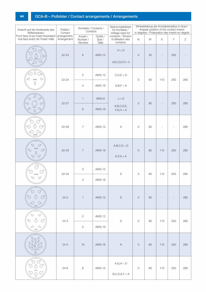
44 GCA-B – Polbilder / Contact arrangements / Arrangements
Ansicht auf die Vorderseite desStifteinsatzes/
Front face of pin insert illustrated/Vue face avant de l’insert mâle
Polbild /Contact
arrangement/Arrangement
Kontakte / Contacts /Contacts
Spannungsklassefür Kontakte /
Voltage class forcontacts / Tension
d’utilisation descontacts
Winkelstellung der Kontakteinsätze in Grad /Angular position of the contact inserts
in degrees / Polarisation des inserts en degrésAnzahl /
Number /Nombre
Größe /Size /Taille
N W X Y Z
22-23 8 AWG 12
H = D
0 35 - 250 -
A,B,C,D,E,F,G = A
22-24
2 AWG 12 C,D,E = D
0 80 110 250 280
4 AWG 16 A,B,F = A
22-27
1 AWG 8 J = D
0 80 - 250 280
8 AWG 16A,B,C,D,E,F,G,H = A
22-28 7 AWG 12 A 0 80 - - 280
22-33 7 AWG 16
A,B,C,D = D
0 80 110 250 280
E,F,G = A
22-34
3 AWG 12
D 0 80 110 250 280
2 AWG 16
24-2 7 AWG 12 D 0 80 - - 280
24-3
2 AWG 12
D 0 80 110 250 280
5 AWG 16
24-5 16 AWG 16 A 0 80 110 250 280
24-6 8 AWG 12
A,G,H = D
0 80 110 250 280
B,C,D,E,F = A
0298_ailb_kat.neu.411 04.03.2005 14:21 Uhr Seite 44
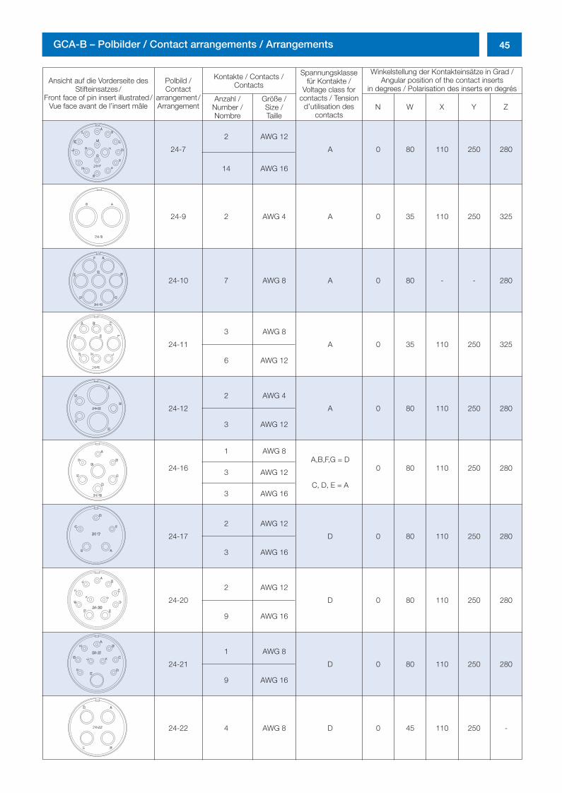
45GCA-B – Polbilder / Contact arrangements / Arrangements
Ansicht auf die Vorderseite desStifteinsatzes/
Front face of pin insert illustrated/Vue face avant de l’insert mâle
Polbild /Contact
arrangement/Arrangement
Kontakte / Contacts /Contacts
Spannungsklassefür Kontakte /
Voltage class forcontacts / Tension
d’utilisation descontacts
Winkelstellung der Kontakteinsätze in Grad /Angular position of the contact inserts
in degrees / Polarisation des inserts en degrésAnzahl /
Number /Nombre
Größe /Size /Taille
N W X Y Z
24-7
2 AWG 12
A 0 80 110 250 280
14 AWG 16
24-9 2 AWG 4 A 0 35 110 250 325
24-10 7 AWG 8 A 0 80 - - 280
24-11
3 AWG 8
A 0 35 110 250 325
6 AWG 12
24-12
2 AWG 4
A 0 80 110 250 280
3 AWG 12
24-16
1 AWG 8A,B,F,G = D
0 80 110 250 2803 AWG 12
3 AWG 16C, D, E = A
24-17
2 AWG 12
D 0 80 110 250 280
3 AWG 16
24-20
2 AWG 12
D 0 80 110 250 280
9 AWG 16
24-21
1 AWG 8
D 0 80 110 250 280
9 AWG 16
24-22 4 AWG 8 D 0 45 110 250 -
0298_ailb_kat.neu.411 04.03.2005 14:21 Uhr Seite 45
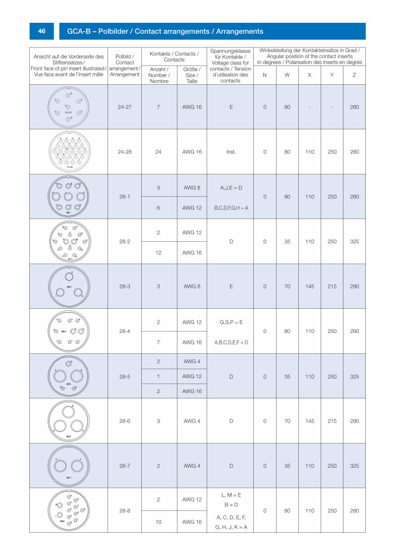
46 GCA-B – Polbilder / Contact arrangements / Arrangements
Ansicht auf die Vorderseite desStifteinsatzes/
Front face of pin insert illustrated/Vue face avant de l’insert mâle
Polbild /Contact
arrangement/Arrangement
Kontakte / Contacts /Contacts
Spannungsklassefür Kontakte /
Voltage class forcontacts / Tension
d’utilisation descontacts
Winkelstellung der Kontakteinsätze in Grad /Angular position of the contact inserts
in degrees / Polarisation des inserts en degrésAnzahl /
Number /Nombre
Größe /Size /Taille
N W X Y Z
24-27 7 AWG 16 E 0 80 - - 280
24-28 24 AWG 16 Inst. 0 80 110 250 280
28-1
3 AWG 8 A,J,E = D
0 80 110 250 280
6 AWG 12 B,C,D,F,G,H = A
28-2
2 AWG 12
D 0 35 110 250 325
12 AWG 16
28-3 3 AWG 8 E 0 70 145 215 290
28-4
2 AWG 12 G,S,P = E
0 80 110 250 280
7 AWG 16 A,B,C,D,E,F = D
28-5
2 AWG 4
D 0 35 110 250 3251 AWG 12
2 AWG 16
28-6 3 AWG 4 D 0 70 145 215 290
28-7 2 AWG 4 D 0 35 110 250 325
2 AWG 12L, M = E
28-8B = D
0 80 110 250 280
10 AWG 16A, C, D, E, F,
G, H, J, K = A
0298_ailb_kat.neu.411 04.03.2005 14:21 Uhr Seite 46
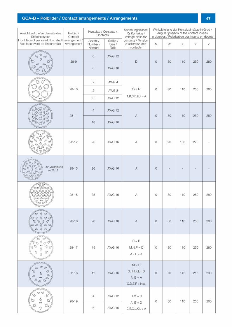
47GCA-B – Polbilder / Contact arrangements / Arrangements
Ansicht auf die Vorderseite desStifteinsatzes/
Front face of pin insert illustrated/Vue face avant de l’insert mâle
Polbild /Contact
arrangement/Arrangement
Kontakte / Contacts /Contacts
Spannungsklassefür Kontakte /
Voltage class forcontacts / Tension
d’utilisation descontacts
Winkelstellung der Kontakteinsätze in Grad /Angular position of the contact inserts
in degrees / Polarisation des inserts en degrésAnzahl /
Number /Nombre
Größe /Size /Taille
N W X Y Z
28-9
6 AWG 12
D 0 80 110 250 280
6 AWG 16
28-10
2 AWG 4
0 80 110 250 2802 AWG 8 G = D
3 AWG 12 A,B,C,D,E,F = A
28-11
4 AWG 12
A 0 80 110 250 280
18 AWG 16
28-12 26 AWG 16 A 0 90 180 270 -
28-13 26 AWG 16 A 0 - - - -
28-15 35 AWG 16 A 0 80 110 250 280
28-16 20 AWG 16 A 0 80 110 250 280
R = B
28-17 15 AWG 16 M,N,P = D 0 80 110 250 280
A - L = A
M = C
28-18 12 AWG 16 G,H,J,K,L = D 0 70 145 215 290A, B = A
C,D,E,F = Inst.
28-19
4 AWG 12 H,M = B
0 80 110 250 280
6 AWG 16
A, B = D
C,E,G,J,K,L = A
100° Verdrehungzu 28-12
0298_ailb_kat.neu.411 04.03.2005 14:21 Uhr Seite 47
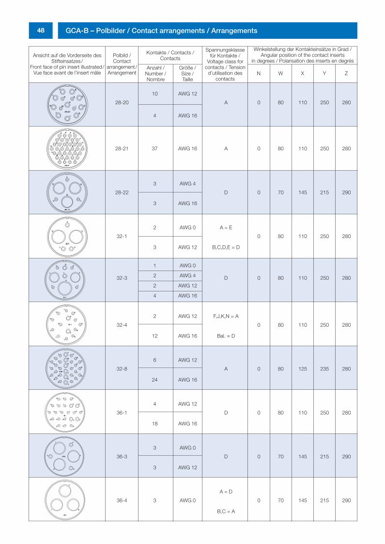
48 GCA-B – Polbilder / Contact arrangements / Arrangements
Ansicht auf die Vorderseite desStifteinsatzes/
Front face of pin insert illustrated/Vue face avant de l’insert mâle
Polbild /Contact
arrangement/Arrangement
Kontakte / Contacts /Contacts
Spannungsklassefür Kontakte /
Voltage class forcontacts / Tension
d’utilisation descontacts
Winkelstellung der Kontakteinsätze in Grad /Angular position of the contact inserts
in degrees / Polarisation des inserts en degrésAnzahl /
Number /Nombre
Größe /Size /Taille
N W X Y Z
28-20
10 AWG 12
A 0 80 110 250 280
4 AWG 16
28-21 37 AWG 16 A 0 80 110 250 280
28-22
3 AWG 4
D 0 70 145 215 290
3 AWG 16
32-1
2 AWG 0 A = E
0 80 110 250 280
3 AWG 12 B,C,D,E = D
32-3
1 AWG 0
D 0 80 110 250 2802 AWG 4
2 AWG 12
4 AWG 16
32-4
2 AWG 12 F,J,K,N = A
0 80 110 250 280
12 AWG 16 Bal. = D
32-8
6 AWG 12
A 0 80 125 235 280
24 AWG 16
36-1
4 AWG 12
D 0 80 110 250 280
18 AWG 16
36-3
3 AWG 0
D 0 70 145 215 290
3 AWG 12
36-4 3 AWG 0
A = D
0 70 145 215 290
B,C = A
0298_ailb_kat.neu.411 04.03.2005 14:21 Uhr Seite 48
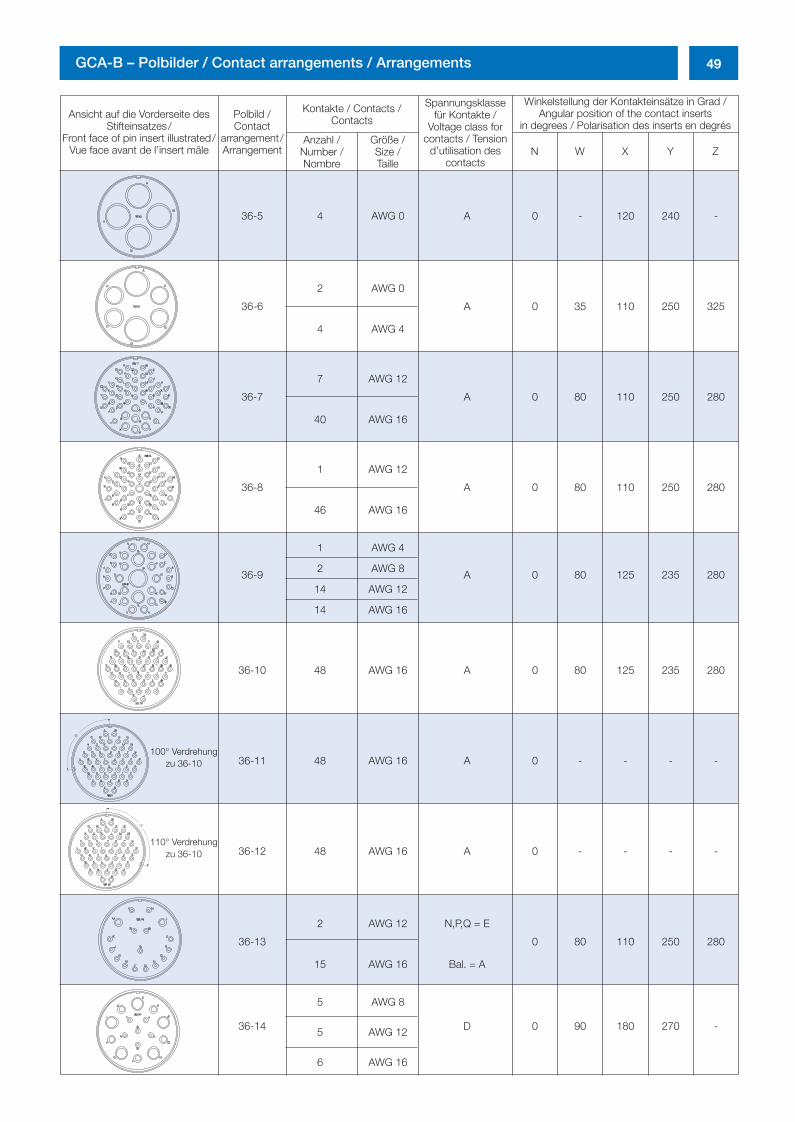
49GCA-B – Polbilder / Contact arrangements / Arrangements
Ansicht auf die Vorderseite desStifteinsatzes/
Front face of pin insert illustrated/Vue face avant de l’insert mâle
Polbild /Contact
arrangement/Arrangement
Kontakte / Contacts /Contacts
Spannungsklassefür Kontakte /
Voltage class forcontacts / Tension
d’utilisation descontacts
Winkelstellung der Kontakteinsätze in Grad /Angular position of the contact inserts
in degrees / Polarisation des inserts en degrésAnzahl /
Number /Nombre
Größe /Size /Taille
N W X Y Z
36-5 4 AWG 0 A 0 - 120 240 -
36-6
2 AWG 0
A 0 35 110 250 325
4 AWG 4
36-7
7 AWG 12
A 0 80 110 250 280
40 AWG 16
36-8
1 AWG 12
A 0 80 110 250 280
46 AWG 16
36-9
1 AWG 4
A 0 80 125 235 2802 AWG 8
14 AWG 12
14 AWG 16
36-10 48 AWG 16 A 0 80 125 235 280
36-11 48 AWG 16 A 0 - - - -
36-12 48 AWG 16 A 0 - - - -
36-13
2 AWG 12 N,P,Q = E
0 80 110 250 280
15 AWG 16 Bal. = A
36-14
5 AWG 8
D 0 90 180 270 -5 AWG 12
6 AWG 16
100° Verdrehungzu 36-10
110° Verdrehungzu 36-10
0298_ailb_kat.neu.411 04.03.2005 14:22 Uhr Seite 49
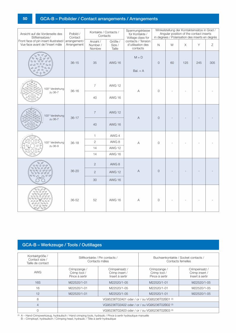
50 GCA-B – Polbilder / Contact arrangements / Arrangements
Ansicht auf die Vorderseite desStifteinsatzes/
Front face of pin insert illustrated/Vue face avant de l’insert mâle
Polbild /Contact
arrangement/Arrangement
Kontakte / Contacts /Contacts
Spannungsklassefür Kontakte /
Voltage class forcontacts / Tension
d’utilisation descontacts
Winkelstellung der Kontakteinsätze in Grad /Angular position of the contact inserts
in degrees / Polarisation des inserts en degrésAnzahl /
Number /Nombre
Größe /Size /Taille
N W X Y Z
36-15 35 AWG 16
M = D
0 60 125 245 305
Bal. = A
36-16
7 AWG 12
A 0 - - - -
40 AWG 16
36-17
7 AWG 12
A 0 - - - -
40 AWG 16
36-18
1 AWG 4
A 0 - - - -2 AWG 8
14 AWG 12
14 AWG 16
36-20
2 AWG 8
A 0 - - - -2 AWG 12
30 AWG 16
36-52 52 AWG 16 A 0 - - - -
100° Verdrehungzu 36-9
100° Verdrehungzu 36-7
100° Verdrehungzu 36-7
GCA-B – Werkzeuge / Tools / Outillages
Kontaktgröße /Contact size /
Taille de contact
Stiftkontakte / Pin contacts /Contacts mâles
Buchsenkontakte / Socket contacts /Contacts femelles
AWGCrimpzange /Crimp tool /Pince à sertir
Crimpeinsatz /Crimp insert /Insert à sertir
Crimpzange /Crimp tool /Pince à sertir
Crimpeinsatz /Crimp insert /Insert à sertir
16S M22520/1-01 M22520/1-05 M22520/1-01 M22520/1-05
16 M22520/1-01 M22520/1-05 M22520/1-01 M22520/1-05
12 M22520/1-01 M22520/1-05 M22520/1-01 M22520/1-05
8 VG95236T02A01 oder / or / ou VG95236T02B01 (3)
4 VG95236T02A02 oder / or / ou VG95236T02B02 (3)
0 VG95236T02A03 oder / or / ou VG95236T02B03 (3)
(3) A – Hand-Crimpwerkzeug, hydraulisch / Hand crimping tools, hydraulic / Pince à sertir hydraulique manuelle B – Crimpkopf, hydraulisch / Crimping head, hydraulic / Tête à sertir hydraulique
0298_ailb_kat.neu.411 04.03.2005 14:22 Uhr Seite 50
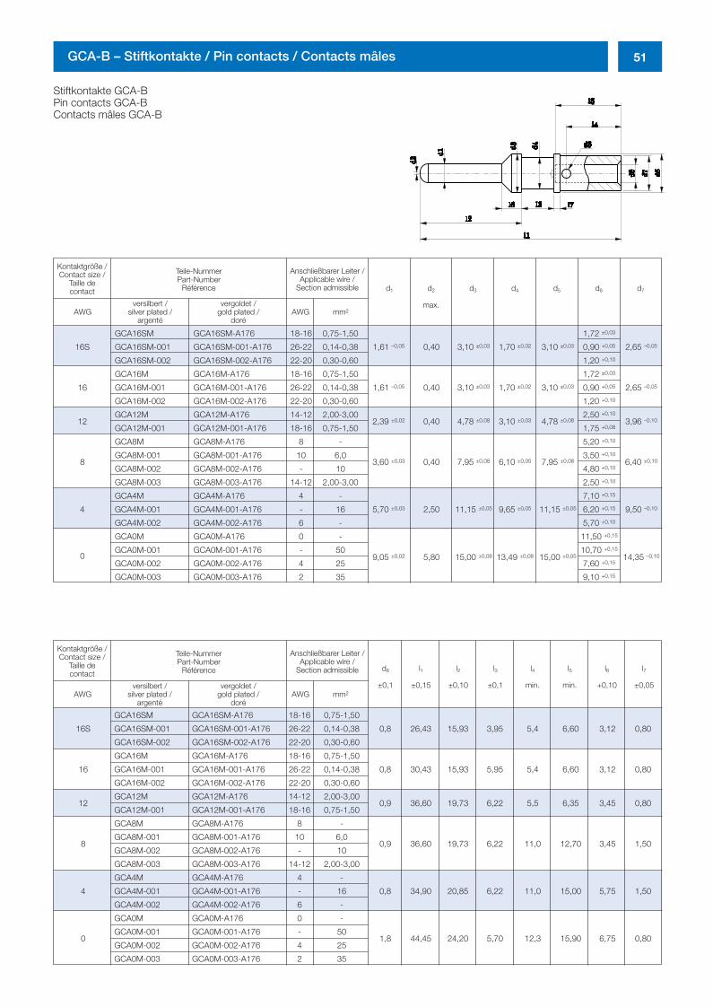
51GCA-B – Stiftkontakte / Pin contacts / Contacts mâles
Stiftkontakte GCA-BPin contacts GCA-BContacts mâles GCA-B
16S
GCA16SM GCA16SM-A176 18-16 0,75-1,50
1,61 –0,05 0,40 3,10 ±0,03 1,70 ±0,02 3,10 ±0,03
1,72 ±0,03
2,65 –0,05GCA16SM-001 GCA16SM-001-A176 26-22 0,14-0,38 0,90 +0,05
GCA16SM-002 GCA16SM-002-A176 22-20 0,30-0,60 1,20 +0,10
16
GCA16M GCA16M-A176 18-16 0,75-1,50
1,61 –0,05 0,40 3,10 ±0,03 1,70 ±0,02 3,10 ±0,03
1,72 ±0,03
2,65 –0,05GCA16M-001 GCA16M-001-A176 26-22 0,14-0,38 0,90 +0,05
GCA16M-002 GCA16M-002-A176 22-20 0,30-0,60 1,20 +0,10
12GCA12M GCA12M-A176 14-12 2,00-3,00
2,39 ±0,02 0,40 4,78 ±0,08 3,10 ±0,03 4,78 ±0,082,50 +0,10
3,96 –0,10
GCA12M-001 GCA12M-001-A176 18-16 0,75-1,50 1,75 +0,08
8
GCA8M GCA8M-A176 8 -
3,60 ±0,03 0,40 7,95 ±0,08 6,10 ±0,05 7,95 ±0,08
5,20 +0,10
6,40 ±0,10GCA8M-001 GCA8M-001-A176 10 6,0 3,50 +0,10
GCA8M-002 GCA8M-002-A176 - 10 4,80 +0,10
GCA8M-003 GCA8M-003-A176 14-12 2,00-3,00 2,50 +0,10
4
GCA4M GCA4M-A176 4 -
5,70 ±0,03 2,50 11,15 ±0,05 9,65 ±0,05 11,15 ±0,05
7,10 +0,15
9,50 –0,10GCA4M-001 GCA4M-001-A176 - 16 6,20 +0,15
GCA4M-002 GCA4M-002-A176 6 - 5,70 +0,10
GCA0M GCA0M-A176 0 - 11,50 +0,15
0GCA0M-001 GCA0M-001-A176 - 50
9,05 ±0,02 5,80 15,00 ±0,08 13,49 ±0,08 15,00 ±0,0510,70 +0,15
14,35 –0,10
GCA0M-002 GCA0M-002-A176 4 25 7,60 +0,15
GCA0M-003 GCA0M-003-A176 2 35 9,10 +0,15
Kontaktgröße /Contact size /
Taille de contact
Kontaktgröße /Contact size /
Taille de contact
Anschließbarer Leiter /Applicable wire /
Section admissible
Teile-NummerPart-Number
Référence
versilbert /silver plated /
argentéAWG AWG mm2
vergoldet /gold plated /
doré
Anschließbarer Leiter /Applicable wire /
Section admissible
Teile-NummerPart-Number
Référence
versilbert /silver plated /
argentéAWG AWG mm2
vergoldet /gold plated /
doré
d1 d2
max.
d3 d4 d5 d6 d7
d8
±0,1
l1
±0,15
l2
±0,10
l3
±0,1
l4
min.
l5
min.
l6
+0,10
l7
±0,05
16S
GCA16SM GCA16SM-A176 18-16 0,75-1,50
0,8 26,43 15,93 3,95 5,4 6,60 3,12 0,80GCA16SM-001 GCA16SM-001-A176 26-22 0,14-0,38
GCA16SM-002 GCA16SM-002-A176 22-20 0,30-0,60
16
GCA16M GCA16M-A176 18-16 0,75-1,50
0,8 30,43 15,93 5,95 5,4 6,60 3,12 0,80GCA16M-001 GCA16M-001-A176 26-22 0,14-0,38
GCA16M-002 GCA16M-002-A176 22-20 0,30-0,60
12GCA12M GCA12M-A176 14-12 2,00-3,00
0,9 36,60 19,73 6,22 5,5 6,35 3,45 0,80GCA12M-001 GCA12M-001-A176 18-16 0,75-1,50
8
GCA8M GCA8M-A176 8 -
0,9 36,60 19,73 6,22 11,0 12,70 3,45 1,50GCA8M-001 GCA8M-001-A176 10 6,0
GCA8M-002 GCA8M-002-A176 - 10
GCA8M-003 GCA8M-003-A176 14-12 2,00-3,00
4
GCA4M GCA4M-A176 4 -
0,8 34,90 20,85 6,22 11,0 15,00 5,75 1,50GCA4M-001 GCA4M-001-A176 - 16
GCA4M-002 GCA4M-002-A176 6 -
0
GCA0M GCA0M-A176 0 -
1,8 44,45 24,20 5,70 12,3 15,90 6,75 0,80GCA0M-001 GCA0M-001-A176 - 50
GCA0M-002 GCA0M-002-A176 4 25
GCA0M-003 GCA0M-003-A176 2 35
0298_ailb_kat.neu.411 04.03.2005 14:22 Uhr Seite 51
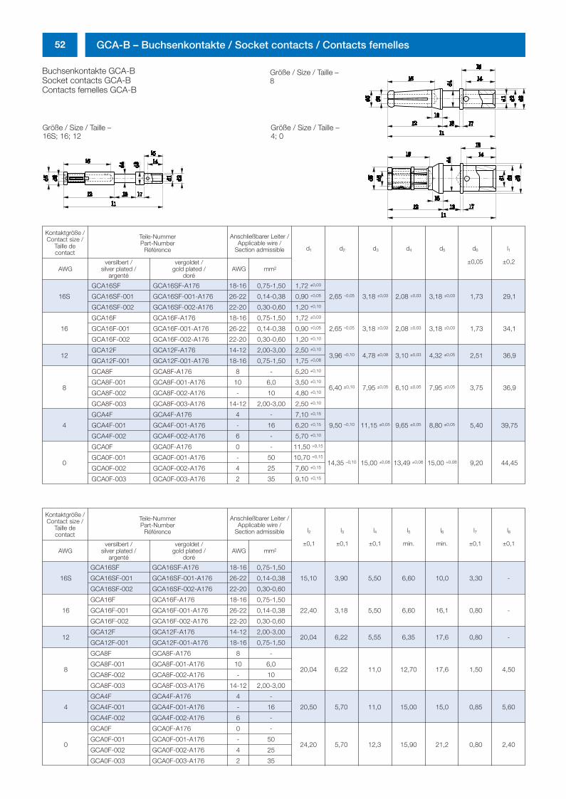
52 GCA-B – Buchsenkontakte / Socket contacts / Contacts femelles
Buchsenkontakte GCA-BSocket contacts GCA-BContacts femelles GCA-B
Größe / Size / Taille – Größe / Size / Taille – 16S; 16; 12 4; 0
Kontaktgröße /Contact size /
Taille de contact
Anschließbarer Leiter /Applicable wire /
Section admissible
Teile-NummerPart-Number
Référence
versilbert /silver plated /
argentéAWG AWG mm2
vergoldet /gold plated /
doré
l2
±0,1
l3
±0,1
l4
±0,1
l5
min.
l6
min.
l7
±0,1
l8
±0,1
16S
GCA16SF GCA16SF-A176 18-16 0,75-1,50
15,10 3,90 5,50 6,60 10,0 3,30 -GCA16SF-001 GCA16SF-001-A176 26-22 0,14-0,38
GCA16SF-002 GCA16SF-002-A176 22-20 0,30-0,60
16
GCA16F GCA16F-A176 18-16 0,75-1,50
22,40 3,18 5,50 6,60 16,1 0,80 -GCA16F-001 GCA16F-001-A176 26-22 0,14-0,38
GCA16F-002 GCA16F-002-A176 22-20 0,30-0,60
12GCA12F GCA12F-A176 14-12 2,00-3,00
20,04 6,22 5,55 6,35 17,6 0,80 -GCA12F-001 GCA12F-001-A176 18-16 0,75-1,50
8
GCA8F GCA8F-A176 8 -
20,04 6,22 11,0 12,70 17,6 1,50 4,50GCA8F-001 GCA8F-001-A176 10 6,0
GCA8F-002 GCA8F-002-A176 - 10
GCA8F-003 GCA8F-003-A176 14-12 2,00-3,00
4
GCA4F GCA4F-A176 4 -
20,50 5,70 11,0 15,00 15,0 0,85 5,60GCA4F-001 GCA4F-001-A176 - 16
GCA4F-002 GCA4F-002-A176 6 -
0
GCA0F GCA0F-A176 0 -
24,20 5,70 12,3 15,90 21,2 0,80 2,40GCA0F-001 GCA0F-001-A176 - 50
GCA0F-002 GCA0F-002-A176 4 25
GCA0F-003 GCA0F-003-A176 2 35
Kontaktgröße /Contact size /
Taille de contact
Anschließbarer Leiter /Applicable wire /
Section admissible
Teile-NummerPart-Number
Référence
versilbert /silver plated /
argentéAWG AWG mm2
vergoldet /gold plated /
doré
d1 d2 d3 d4 d5 d6
±0,05
l1
±0,2
16S
GCA16SF GCA16SF-A176 18-16 0,75-1,50 1,72 ±0,03
2,65 –0,05 3,18 ±0,03 2,08 ±0,03 3,18 ±0,03 1,73 29,1GCA16SF-001 GCA16SF-001-A176 26-22 0,14-0,38 0,90 +0,05
GCA16SF-002 GCA16SF-002-A176 22-20 0,30-0,60 1,20 +0,10
16
GCA16F GCA16F-A176 18-16 0,75-1,50 1,72 ±0,03
2,65 –0,05 3,18 ±0,03 2,08 ±0,03 3,18 ±0,03 1,73 34,1GCA16F-001 GCA16F-001-A176 26-22 0,14-0,38 0,90 +0,05
GCA16F-002 GCA16F-002-A176 22-20 0,30-0,60 1,20 +0,10
12GCA12F GCA12F-A176 14-12 2,00-3,00 2,50 +0,10
3,96 –0,10 4,78 ±0,08 3,10 ±0,03 4,32 ±0,05 2,51 36,9GCA12F-001 GCA12F-001-A176 18-16 0,75-1,50 1,75 +0,08
8
GCA8F GCA8F-A176 8 - 5,20 +0,10
6,40 ±0,10 7,95 ±0,05 6,10 ±0,05 7,95 ±0,05 3,75 36,9GCA8F-001 GCA8F-001-A176 10 6,0 3,50 +0,10
GCA8F-002 GCA8F-002-A176 - 10 4,80 +0,10
GCA8F-003 GCA8F-003-A176 14-12 2,00-3,00 2,50 +0,10
4
GCA4F GCA4F-A176 4 - 7,10 +0,15
9,50 –0,10 11,15 ±0,05 9,65 ±0,05 8,80 ±0,05 5,40 39,75GCA4F-001 GCA4F-001-A176 - 16 6,20 +0,15
GCA4F-002 GCA4F-002-A176 6 - 5,70 +0,10
0
GCA0F GCA0F-A176 0 - 11,50 +0,15
14,35 –0,10 15,00 ±0,08 13,49 ±0,08 15,00 +0,08 9,20 44,45GCA0F-001 GCA0F-001-A176 - 50 10,70 +0,15
GCA0F-002 GCA0F-002-A176 4 25 7,60 +0,15
GCA0F-003 GCA0F-003-A176 2 35 9,10 +0,15
Größe / Size / Taille – 8
0298_ailb_kat.neu.411 04.03.2005 14:22 Uhr Seite 52

Amphenol-Air LB GmbH · Am Kleinbahnhof 4 · D-66740 Saarlouis
Telefon +49 (0) 68 31 98 10 - 0 · Telefax +49 (0) 68 31 98 10-20 · E-mail: [email protected]
http://www.amphenol-airlb.de
Ser
ie G
CB
-B/G
CA
-BG
edru
ckt a
uf c
hlor
frei g
eble
icht
em P
apie
r, Ä
nder
unge
n vo
rbeh
alte
n.C
opyr
ight
02/
05 b
y A
mph
enol
-Air
LB G
mbH
, Ger
man
y
0298_ailb_titel.411 07.03.2005 13:37 Uhr Seite 1