bedienungsanleitung diagnosemodul operating instructions ... · important: since the unit has been...
TRANSCRIPT
BedienungsanleitungDiagnosemodul
Operating instructionsDiagnostic module
ecomat 100 Typ R 360
articel no: EC2021
Steuerungssysteme
Seite / Page 2
Technische Beschreibung Diagnosemodul, Stand März 1999
Hinweis zur Gewährleistung
Dieses Beschreibung wurde unter Beachtung der größtmöglichen Sorgfalt erstellt. Gleichwohl kann keineGarantie für die Richtigkeit des Inhalts übernommen werden.
Da sich Fehler trotz intensiver Bemühungen nie vollständig vermeiden lassen, sind wir für Hinweisejederzeit dankbar.
Im übrigen behalten wir uns technische Änderungen der Produkte vor, so daß sich auch soweitAbweichungen vom Inhalt des Handbuches ergeben können.
Technical description diagnostic module, March 1999
Note on guarantee
Utmost care was taken when writing this description. Nevertheless, we cannot guarantee that the contentsare correct.
Since it is impossible to avoid mistakes despite intensive efforts, we always appreciate indications.
We reserve the right to make technical alterations to the products so that deviations from the contents ofthe documentation may result.
Steuerungssysteme
Seite / Page 3
1. Sicherheitshinweise
Befolgen Sie die Angaben der Beschreibung. Nichtbeachten der Hinweise, Betrieb außerhalb dernachstehend bestimmungsgemäßen Verwendung, falsche Installation oder fehlerhafte Handhabungkönnen schwerwiegende Beeinträchtigungen der Sicherheit von Menschen und Anlagen zur Folge haben.
Die Anleitung richtet sich an Personen, die im Sinne der EMV- und der Niederspannungs-Richtlinie als“fachkundig” angesehen werden können und ist von einer Elektrofachkraft (Programmierer bzw.Servicetechniker) einzubauen und in Betrieb zu setzen.
Diese Beschreibung ist Bestandteil des Gerätes. Sie enthält Texte und Abbildungen zum korrektenUmgang in Verbindung mit der Steuerung und muß vor einer Installation oder dem Einsatz gelesenwerden.
Da das Gerät mit einer externen Gleichspannung (12/24 V) versorgt werden muß, ist darauf zu achten,daß diese extern gemäß den Kriterien für sichere Kleinspannung (SELV) erzeugt und zugeführt wird, dadiese Spannung ohne weitere Maßnahmen zur Versorgung der angeschlossenen Steuerung, derSensorik und der Aktorik zur Verfügung gestellt wird.
Die Verdrahtung aller in Zusammenhang mit dem SELV-Kreis des Geräts stehenden Signale mußebenfalls den SELV-Kriterien entsprechen (sichere Schutzkleinspannung, galvanisch sicher getrennt vonanderen Stromkreisen).
Wird die extern zugeführte SELV-Spannung extern geerdet (SELV wird zu PELV), so geschieht dies inder Verantwortung des Betreibers und im Rahmen der dort geltenden nationalen Installations-Vorschriften. Alle Aussagen in dieser Bedienungsanleitung beziehen sich auf das bezügl. der SELV-Spannung nicht geerdete Gerät.
An den Anschlußklemmen dürfen nur die in den technischen Daten, bzw. auf dem Geräteaufdruckangegebenen Signale eingespeist werden.
Das Gerät ist gemäß nachstehender technischer Spezifikation in einem weiten Umgebungs-Temperaturbereich betreibbar. Aufgrund der zusätzlichen Eigenerwärmung kann es an den Gehäuse-Wandungen beim Berühren in heißer Umgebung zu hohen wahrnehmbaren Temperaturen kommen.
Bei Fehlfunktionen oder Unklarheiten setzen Sie sich bitte mit dem Hersteller in Verbindung.
2. Bestimmungsgemäße Verwendung
Die Diagnosebox für das Steuerungssystem ecomat 100 Typ R 360 dient zum Austesten der Applikations-Software und Überprüfen der an den Ein- und Ausgängen anliegenden Potentiale.
Das Gerät ist so ausgeführt, daß es für alle Ein-/Ausgangskonfigurationen des ecomat R 360 genutztwerden kann.
Wichtig: Eine Verwendung mit anderen Steuerungen kann zu Zerstörung der Diagnosebox bzw. der Fremdsteuerung führen.
Steuerungssysteme
Seite / Page 4
3. Technische Daten
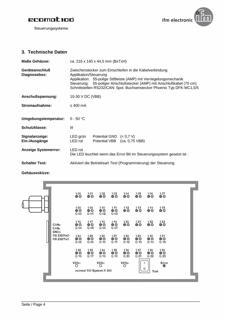
Maße Gehäuse: ca. 216 x 140 x 44,5 mm (BxTxH)
Geräteanschluß Zwischenstecker zum Einschleifen in die KabelverbindungDiagnosebox: Applikation/Steuerung
Applikation: 55-polige Stiftleiste (AMP) mit VerriegelungsmechanikSteuerung: 55-poliger Anschlußstecker (AMP) mit Anschlußkabel (70 cm)Schnittstellen RS232/CAN: 5pol. Buchsenstecker Phoenix Typ DFK-MC1,5/5
Anschußspannung: 10-30 V DC (VBB)
Stromaufnahme: ≤ 400 mA
Umgebungstemperatur: 0 - 50 °C
Schutzklasse: III
Signalanzeige: LED grün Potential GND (< 0,7 V)Ein-/Ausgänge LED rot Potential VBB (ca. 0,75 VBB)
Anzeige Systemerror: LED rotDie LED leuchtet wenn das Error-Bit im Steuerungssystem gesetzt ist .
Schalter Test: Aktiviert die Betriebsart Test (Programmierung) der Steuerung.
Gehäuseskizze:
Steuerungssysteme
Seite / Page 5
4. Anwendung
Mit der Diagnosebox können die Potentiale an den einzelnen Ein- und Ausgangskanälen angezeigtwerden. Außerdem stehen die RS232 bzw. CAN-Schnittstelle zur Systemdiagnose, Programmierung undKommunikation für externe Komponenten zur Verfügung.
Wichtig: Da das Gerät universell ausgelegt ist, müssen nicht immer alle Funktionen zur erfügung stehen. Vor Anschluß an die Steuerung muß daher deren Konfiguration überprüft werden.
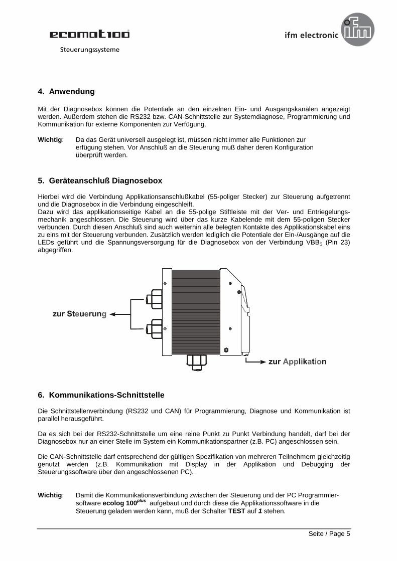
5. Geräteanschluß Diagnosebox
Hierbei wird die Verbindung Applikationsanschlußkabel (55-poliger Stecker) zur Steuerung aufgetrenntund die Diagnosebox in die Verbindung eingeschleift.Dazu wird das applikationsseitige Kabel an die 55-polige Stiftleiste mit der Ver- und Entriegelungs-mechanik angeschlossen. Die Steuerung wird über das kurze Kabelende mit dem 55-poligen Steckerverbunden. Durch diesen Anschluß sind auch weiterhin alle belegten Kontakte des Applikationskabel einszu eins mit der Steuerung verbunden. Zusätzlich werden lediglich die Potentiale der Ein-/Ausgänge auf dieLEDs geführt und die Spannungsversorgung für die Diagnosebox von der Verbindung VBBS (Pin 23)abgegriffen.
6. Kommunikations-Schnittstelle
Die Schnittstellenverbindung (RS232 und CAN) für Programmierung, Diagnose und Kommunikation istparallel herausgeführt.
Da es sich bei der RS232-Schnittstelle um eine reine Punkt zu Punkt Verbindung handelt, darf bei derDiagnosebox nur an einer Stelle im System ein Kommunikationspartner (z.B. PC) angeschlossen sein.
Die CAN-Schnittstelle darf entsprechend der gültigen Spezifikation von mehreren Teilnehmern gleichzeitiggenutzt werden (z.B. Kommunikation mit Display in der Applikation und Debugging derSteuerungssoftware über den angeschlossenen PC).
Wichtig: Damit die Kommunikationsverbindung zwischen der Steuerung und der PC Programmier-software ecolog 100plus aufgebaut und durch diese die Applikationssoftware in die Steuerung geladen werden kann, muß der Schalter TEST auf 1 stehen.
Steuerungssysteme
Seite / Page 6
7. Funktion der LEDs bei der Diagnosebox
Jedem Ein-/ Ausgangskanal sind zwei LEDs zugeordnet. Je nach Potential des angeschlossenen Ein-und/oder Ausgangs leuchtet die grüne bzw. die rote LED.
Bei Steuerungskanälen bei denen sowohl der Eingang wie auch der Ausgang bestückt ist (bidirektionaleEin-/Ausgänge), wird die Zustand der LEDs gleichzeitig vom Potential am Eingang und am Ausgangbeeinflußt.
Hinweis: Leuchtet bei einem Ein-/ Ausgangskanal keine LED, ist bei diesem weder der Ein- noch derAusgang bestückt. Bei den Analogkanälen leuchten die LEDs nur wenn die entsprechendenSchaltschwellen (ca. 0,75 VBB) überschritten werden.
Benennung der Ein-/Ausgangskanäle
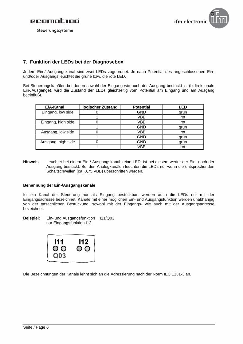
Ist ein Kanal der Steuerung nur als Eingang bestückbar, werden auch die LEDs nur mit derEingangsadresse bezeichnet. Kanäle mit einer möglichen Ein- und Ausgangsfunktion werden unabhängigvon der tatsächlichen Bestückung, sowohl mit der Eingangs- wie auch mit der Ausgangsadressebezeichnet.
Beispiel: Ein- und Ausgangsfunktion I11/Q03nur Eingangsfunktion I12
Die Bezeichnungen der Kanäle lehnt sich an die Adressierung nach der Norm IEC 1131-3 an.
E/A-Kanal logischer Zustand Potential LEDEingang, low side 0 GND grün
1 VBB rotEingang, high side 0 VBB rot
1 GND grünAusgang, low side 0 VBB rot
1 GND grünAusgang, high side 0 GND grün
1 VBB rot
Steuerungssysteme
Seite / Page 7
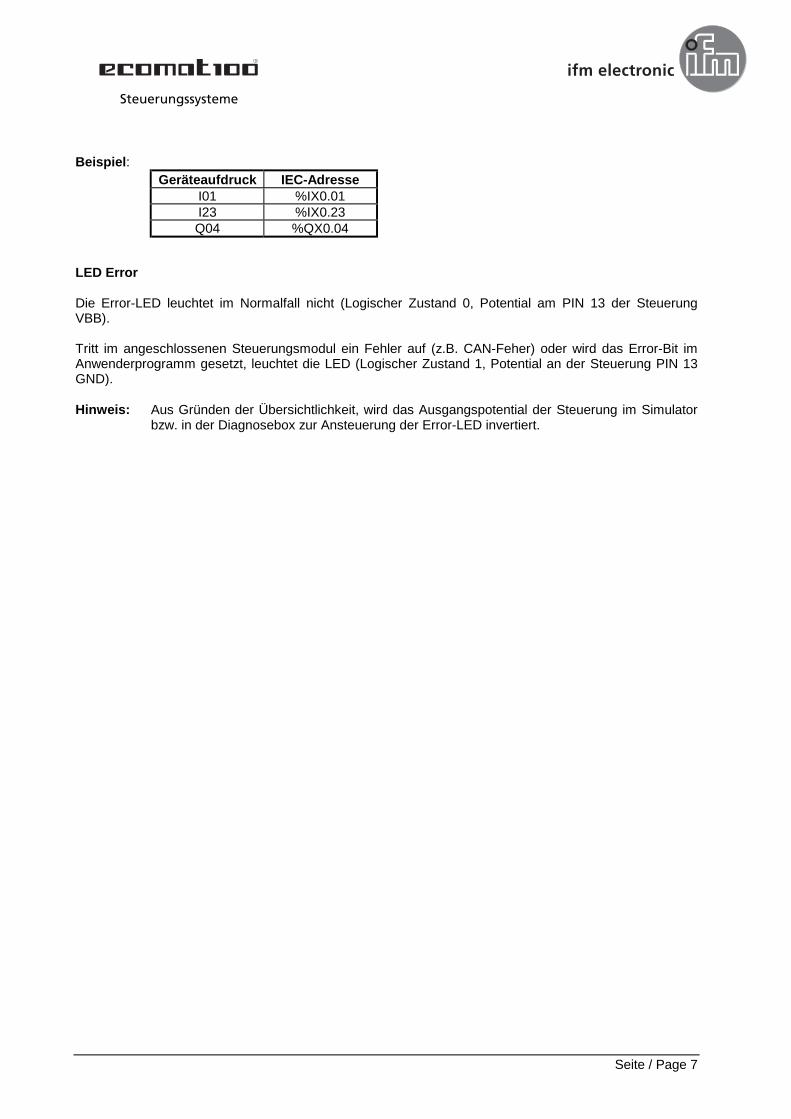
Beispiel:
LED Error
Die Error-LED leuchtet im Normalfall nicht (Logischer Zustand 0, Potential am PIN 13 der SteuerungVBB).
Tritt im angeschlossenen Steuerungsmodul ein Fehler auf (z.B. CAN-Feher) oder wird das Error-Bit imAnwenderprogramm gesetzt, leuchtet die LED (Logischer Zustand 1, Potential an der Steuerung PIN 13GND).
Hinweis: Aus Gründen der Übersichtlichkeit, wird das Ausgangspotential der Steuerung im Simulatorbzw. in der Diagnosebox zur Ansteuerung der Error-LED invertiert.
Geräteaufdruck IEC-AdresseI01 %IX0.01I23 %IX0.23Q04 %QX0.04
Steuerungssysteme
Seite / Page 8
1. Safety instructions
Observe the information of the description. Non-observance of the notes, operation which is not inaccordance with use as prescribed below, wrong installation or handling can result in serious harmconcerning the safety of persons and plant.
The instructions are for authorised persons according to the EMC and low voltage guidelines. Thecontrollers must be installed and commissioned by a skilled electrician (programmer or servicetechnician).
This description is part of the unit. It contains texts and drawings concerning the correct handling of thecontroller and must be read before installation or use.
Since the unit has to be supplied with an external DC voltage (12/24 V) it must be ensured that theexternal voltage is generated and supplied according to the criteria for safety extra-low voltage (SELV) asthis is supplied without further measures to the connected controller, the sensors, and the actuators.
The wiring of all signals in connection with the SELV circuit of the unit must also comply with the SELVcriteria (safe extra-low voltage, safe electrical separation from other electric circuits).
If the supplied SELV voltage has an external connection to ground (SELV becomes PELV) theresponsibility lies with the user and the respective national regulations for installation must be compliedwith. All statements in these operating instructions refer to the unit the SELV voltage of which is notgrounded.
The terminals may only be supplied with the signals indicated in the technical data or on the unit label andonly the approved accessories of ifm electronic gmbh may be connected.
The unit can be operated within a wide temperature range according to the technical specificationindicated below. Due to the additional self-heating the housing walls can have high perceptibletemperatures when touched in hot environments.
In case of malfunctions or uncertainties please contact the manufacturer.
2. Function and features
The diagnostic box for the ecomat 100 control system type R 360 has been designed for testingapplication software and for checking the potentials of the inputs and outputs.
The unit has been designed in a way that it can be used for all input and output configurations of theecomat R 360.
Important: When used for other controllers the diagnostic box or the other controller can be destroyed.
Steuerungssysteme
Seite / Page 9
3. Technical data
Dimensions housing: approx. 216 x 140 x 44.5 mm (WxDxH)
Unit connection adapter plug to be looped into the cable connectionDiagnostic box: application/controller
Application: 55-pin connector (AMP) with latching mechanismController: 55-pin connector (AMP) with cable (70 cm)Interfaces RS232/CAN: 5-pin female connector Phoenix type DFK-MC1,5/5
Supply voltage: 10-30 V DC (VBB)
Current consumption: ≤ 400 mA
Operating temperature: 0 - 50 °C
Protection class: III
Signal indication: LED green potential GND (< 0.7 V)Inputs/outputs LED red potential VBB (approx. 0.75 VBB)
Indication system error: LED redThe LED lights when the error bit in the control system is set.
Test switch: activates the Test mode (programming) of the controller.
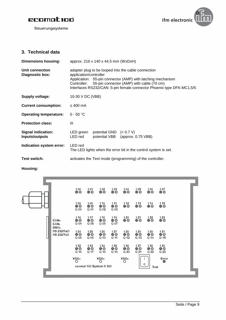
Housing:
Steuerungssysteme
Seite / Page 10
4. Application
The diagnostic box enables the indication of the potentials of the individual input and output channels. TheRS232 and CAN interfaces for system diagnosis, programming and communication for externalcomponents are also available.
Important: Since the unit has been designed for all controller configurations, not all functions mustalways be available. Before connection to the controller its configuration must thus bechecked.
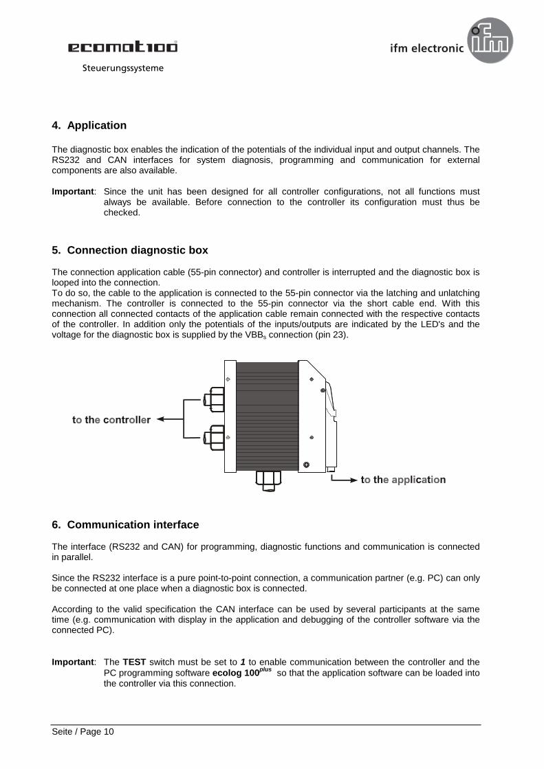
5. Connection diagnostic box
The connection application cable (55-pin connector) and controller is interrupted and the diagnostic box islooped into the connection.To do so, the cable to the application is connected to the 55-pin connector via the latching and unlatchingmechanism. The controller is connected to the 55-pin connector via the short cable end. With thisconnection all connected contacts of the application cable remain connected with the respective contactsof the controller. In addition only the potentials of the inputs/outputs are indicated by the LED's and thevoltage for the diagnostic box is supplied by the VBBs connection (pin 23).
6. Communication interface
The interface (RS232 and CAN) for programming, diagnostic functions and communication is connectedin parallel.
Since the RS232 interface is a pure point-to-point connection, a communication partner (e.g. PC) can onlybe connected at one place when a diagnostic box is connected.
According to the valid specification the CAN interface can be used by several participants at the sametime (e.g. communication with display in the application and debugging of the controller software via theconnected PC).
Important: The TEST switch must be set to 1 to enable communication between the controller and thePC programming software ecolog 100plus so that the application software can be loaded intothe controller via this connection.
Steuerungssysteme
Seite / Page 11
7. LED function of the diagnostic box
2 LED's are allocated to each input/output channel. Depending on the potential of the connected inputand/or output the green or the red LED lights.
For controller channels where the input as well as the output is configured (bi-directional inputs/outputs)the LED status depends on the potential of the input and the output at the same time.
Note: If no LED lights for one input/output channel, neither the input nor the output are configured.For the output channels the LED's light only if the respective switching thresholds (approx.0.75 VBB) are exceeded.
Designation of the input/output channels
If a channel of the controller can only be configured as an input, the LED's only have the designation of theinput address. Channels with a possible input and output function have the designation of the input as wellas the output address irrespective of the actual configuration.
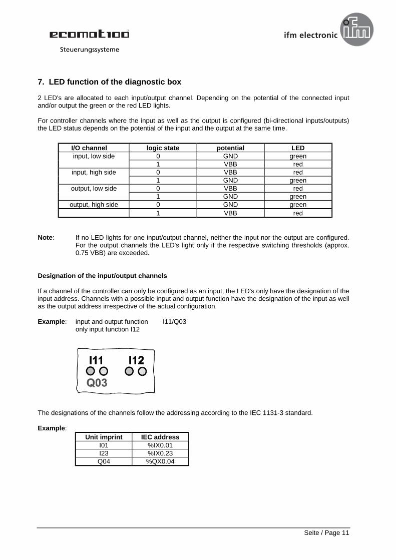
Example: input and output function I11/Q03only input function I12
The designations of the channels follow the addressing according to the IEC 1131-3 standard.
Example:
I/O channel logic state potential LEDinput, low side 0 GND green
1 VBB redinput, high side 0 VBB red
1 GND greenoutput, low side 0 VBB red
1 GND greenoutput, high side 0 GND green
1 VBB red
Unit imprint IEC addressI01 %IX0.01I23 %IX0.23Q04 %QX0.04
Steuerungssysteme
Seite / Page 12
LED Error
Normally the error LED does not light (logic state 0, potential at pin 13 of the VBB controller).
The LED lights (logic state 1, potential at the controller pin 13 GND) in the case of an error in theconnected controller module (e.g. CAN error) or if the error bit is set in the user program.
Note: For clarity reasons the output potential of the controller in the simulator or in the diagnosticbox which triggers the Error LED is inverted.
Steuerungssysteme