cartridge ddr - kollmorgenhistory edition remarks 10 / 2010 first multilingual edition 12 / 2010...
TRANSCRIPT
Cartridge DDR
Deutsch Synchron Servomotor für DirektantriebeEnglish Synchronous Servomotors for Direct DrivesItaliano Servomotori Sincroni per gli azionamenti direttiEspañol Servomotores Sincronos para las impulsiones directas
Product Safety GuideEdition 02/2020Originalsprache DeutschEuropean Version
File ddc_deis.***
Bewahren Sie das Handbuch als Produktbestandteil währendder Lebensdauer des Produktes auf. Geben Sie das Handbuchan nachfolgende Benutzer oder Besitzer des Produktes weiter.
Keep the manual as a product component during the life span ofthe product. Pass the manual to future users / owners of theproduct.
Conservare il manuale per l’intera durata del prodotto. In caso dicambio di proprietà il manuale deve essere fornito al nuovo uti-lizzatore quale parte integrante del prodotto.
Conserve el manual durante toda la vida útil del producto.Entregue el manual a posteriores usuarios o propietarios delproducto.
History
Edition Remarks
10 / 2010 First multilingual edition
12 / 2010 Company name and address, CE certificate
05 / 2011 Motor power cable diameter updated
09 / 2012 CE certificate, Mounting flange and shaft requirement 04/05/06 corrected (dim E), formal improvements
06 / 2015 CE certificate removed, technical data updated
03 / 2016Dimensions (tolerances) updated, assembling/disassembling details removed, symbols acc. to ISO 82079,UL & CE & EAC & RoHS & REACH information added, LVD 2014-35-EG, SpeedTec-Ready connectors
04 / 2017 Electrical data updated
02 / 2020EAC contact Russia updated, current limit for M40 in wiring diagram updated, data updated, warning pa-nels updated
Technische Änderungen, die der Verbesserung der Geräte dienen, vorbehalten!Originalbetriebsanleitung, gedruckt in der BRDAlle Rechte vorbehalten. Kein Teil des Werkes darf in irgendeiner Form (Druck, Fotokopie, Mikrofilm oder ineinem anderen Verfahren) ohne schriftliche Genehmigung der Firma Kollmorgen Europe GmbH reproduziertoder unter Verwendung elektronischer Systeme verarbeitet, vervielfältigt oder verbreitet werden.
Technical changes to improve the performance of the equipment may be made without prior notice!Translation of the original manual, printed in the Federal Republic of GermanyAll rights reserved. No part of this work may be reproduced in any form (by printing, photocopying, microfilmor any other method) or stored, processed, copied or distributed by electronic means without the written per-mission of Kollmorgen Europe GmbH.
Il produttore si riserva la facoltà di apportare modifiche tecniche volte al miglioramento degli appa-recchiTraduzione del manuale originale, stampato nella Repubblica federale tedescaTutti i diritti riservati. Nessuna parte di questo documento può essere rielaborata, riprodotta in qualsiasiforma (stampa, fotocopia, microfilm o altro processo) o diffusa mediante l'uso di sistemi elettronici senza l'ap-provazione scritta della ditta Kollmorgen Europe GmbH o rielaborata, riprodotta o diffusa mediante l’uso disistemi elettronici.
Reservado el derecho de introducir modificaciones técnicas para la mejora de los equiposTraducción del manual original, impreso en la RFAReservados todos los derechos. Prohibida la reproducción total o parcial de la presente obra por cualquiermedio (impresión, fotocopia, microfilm u otros), así como su procesamiento, reproducción y divulgación pormedio de sistemas electrónicos, sin expresa autorización escrita de la empresa Kollmorgen Europe GmbH.e
tocdruck
1 Allgemeines1.1 Über dieses Handbuch . . . . . . . . . . . . . . . . . . . . . . . . . . . . . . . . . . . . . . . . . . . . . . . . . . . . . . . . . . . .91.2 Verwendete Symbole . . . . . . . . . . . . . . . . . . . . . . . . . . . . . . . . . . . . . . . . . . . . . . . . . . . . . . . . . . . . .91.3 Verwendete Abkürzungen . . . . . . . . . . . . . . . . . . . . . . . . . . . . . . . . . . . . . . . . . . . . . . . . . . . . . . . . .9
2 Sicherheit2.1 Das sollten Sie beachten . . . . . . . . . . . . . . . . . . . . . . . . . . . . . . . . . . . . . . . . . . . . . . . . . . . . . . . . .102.2 Bestimmungsgemäße Verwendung . . . . . . . . . . . . . . . . . . . . . . . . . . . . . . . . . . . . . . . . . . . . . . . . .112.3 Nicht bestimmungsgemäße Verwendung . . . . . . . . . . . . . . . . . . . . . . . . . . . . . . . . . . . . . . . . . . . .11
3 Handhabung3.1 Transport . . . . . . . . . . . . . . . . . . . . . . . . . . . . . . . . . . . . . . . . . . . . . . . . . . . . . . . . . . . . . . . . . . . . .123.2 Verpackung. . . . . . . . . . . . . . . . . . . . . . . . . . . . . . . . . . . . . . . . . . . . . . . . . . . . . . . . . . . . . . . . . . . .123.3 Lagerung. . . . . . . . . . . . . . . . . . . . . . . . . . . . . . . . . . . . . . . . . . . . . . . . . . . . . . . . . . . . . . . . . . . . . .123.4 Wartung / Reinigung. . . . . . . . . . . . . . . . . . . . . . . . . . . . . . . . . . . . . . . . . . . . . . . . . . . . . . . . . . . . .123.5 Reparatur . . . . . . . . . . . . . . . . . . . . . . . . . . . . . . . . . . . . . . . . . . . . . . . . . . . . . . . . . . . . . . . . . . . . .123.6 Entsorgung . . . . . . . . . . . . . . . . . . . . . . . . . . . . . . . . . . . . . . . . . . . . . . . . . . . . . . . . . . . . . . . . . . . .12
4 Produktidentif izierung4.1 Lieferumfang. . . . . . . . . . . . . . . . . . . . . . . . . . . . . . . . . . . . . . . . . . . . . . . . . . . . . . . . . . . . . . . . . . .134.2 Typenschild. . . . . . . . . . . . . . . . . . . . . . . . . . . . . . . . . . . . . . . . . . . . . . . . . . . . . . . . . . . . . . . . . . . .134.3 Typenschlüssel . . . . . . . . . . . . . . . . . . . . . . . . . . . . . . . . . . . . . . . . . . . . . . . . . . . . . . . . . . . . . . . . .14
5 Technische Beschreibung5.1 Allgemeine technische Daten . . . . . . . . . . . . . . . . . . . . . . . . . . . . . . . . . . . . . . . . . . . . . . . . . . . . . .15
5.1.1 Bauform. . . . . . . . . . . . . . . . . . . . . . . . . . . . . . . . . . . . . . . . . . . . . . . . . . . . . . . . . . . . . . . . . .155.1.2 Flansch . . . . . . . . . . . . . . . . . . . . . . . . . . . . . . . . . . . . . . . . . . . . . . . . . . . . . . . . . . . . . . . . . .155.1.3 Schutzart . . . . . . . . . . . . . . . . . . . . . . . . . . . . . . . . . . . . . . . . . . . . . . . . . . . . . . . . . . . . . . . . .165.1.4 Isolierstoffklasse . . . . . . . . . . . . . . . . . . . . . . . . . . . . . . . . . . . . . . . . . . . . . . . . . . . . . . . . . . .165.1.5 Oberfläche . . . . . . . . . . . . . . . . . . . . . . . . . . . . . . . . . . . . . . . . . . . . . . . . . . . . . . . . . . . . . . . .165.1.6 Schutzeinrichtung . . . . . . . . . . . . . . . . . . . . . . . . . . . . . . . . . . . . . . . . . . . . . . . . . . . . . . . . . .165.1.7 Anschlusstechnik. . . . . . . . . . . . . . . . . . . . . . . . . . . . . . . . . . . . . . . . . . . . . . . . . . . . . . . . . . .165.1.8 Rückführeinheit . . . . . . . . . . . . . . . . . . . . . . . . . . . . . . . . . . . . . . . . . . . . . . . . . . . . . . . . . . . .16
6 Mechanische Installation6.1 Wichtige Hinweise . . . . . . . . . . . . . . . . . . . . . . . . . . . . . . . . . . . . . . . . . . . . . . . . . . . . . . . . . . . . . .176.2 Typen C04/CH04, C05/CH05 und C06/CH06 . . . . . . . . . . . . . . . . . . . . . . . . . . . . . . . . . . . . . . . . .18
6.2.1 Anforderungen an Montageflansch und Welle . . . . . . . . . . . . . . . . . . . . . . . . . . . . . . . . . . . .186.2.2 Montage, Demontage . . . . . . . . . . . . . . . . . . . . . . . . . . . . . . . . . . . . . . . . . . . . . . . . . . . . . . .18
6.3 Typen C09/CH09 und C13/CH13. . . . . . . . . . . . . . . . . . . . . . . . . . . . . . . . . . . . . . . . . . . . . . . . . . .196.3.1 Anforderungen an Montageflansch und Welle . . . . . . . . . . . . . . . . . . . . . . . . . . . . . . . . . . . .196.3.2 Montage, Demontage . . . . . . . . . . . . . . . . . . . . . . . . . . . . . . . . . . . . . . . . . . . . . . . . . . . . . . .19
7 Elektrische Installation7.1 Wichtige Hinweise . . . . . . . . . . . . . . . . . . . . . . . . . . . . . . . . . . . . . . . . . . . . . . . . . . . . . . . . . . . . . .207.2 Anschluss der Motoren mit vorkonfektionierten Kabeln . . . . . . . . . . . . . . . . . . . . . . . . . . . . . . . . . .207.3 Leitfaden für die elektrische Installation . . . . . . . . . . . . . . . . . . . . . . . . . . . . . . . . . . . . . . . . . . . . . .21
8 Inbetriebnahme8.1 Wichtige Hinweise . . . . . . . . . . . . . . . . . . . . . . . . . . . . . . . . . . . . . . . . . . . . . . . . . . . . . . . . . . . . . .228.2 Leitfaden für die Inbetriebnahme . . . . . . . . . . . . . . . . . . . . . . . . . . . . . . . . . . . . . . . . . . . . . . . . . . .228.3 Beseitigen von Störungen . . . . . . . . . . . . . . . . . . . . . . . . . . . . . . . . . . . . . . . . . . . . . . . . . . . . . . . .23
9 Technische Daten9.1 Begriffsdefinitionen . . . . . . . . . . . . . . . . . . . . . . . . . . . . . . . . . . . . . . . . . . . . . . . . . . . . . . . . . . . . . .24
Servomotoren Cartridge DDR Deutsch - 3
Kollmorgen 02/2020 Inhaltsverzeichnis
Seite
DE
UT
SC
H
10 General10.1 About this manual . . . . . . . . . . . . . . . . . . . . . . . . . . . . . . . . . . . . . . . . . . . . . . . . . . . . . . . . . . . . . . .2510.2 Symbols used . . . . . . . . . . . . . . . . . . . . . . . . . . . . . . . . . . . . . . . . . . . . . . . . . . . . . . . . . . . . . . . . . .2510.3 Abbreviations used . . . . . . . . . . . . . . . . . . . . . . . . . . . . . . . . . . . . . . . . . . . . . . . . . . . . . . . . . . . . . .25
11 Safety11.1 You should pay attention to this . . . . . . . . . . . . . . . . . . . . . . . . . . . . . . . . . . . . . . . . . . . . . . . . . . . .2611.2 Use as directed. . . . . . . . . . . . . . . . . . . . . . . . . . . . . . . . . . . . . . . . . . . . . . . . . . . . . . . . . . . . . . . . .2711.3 Prohibited use. . . . . . . . . . . . . . . . . . . . . . . . . . . . . . . . . . . . . . . . . . . . . . . . . . . . . . . . . . . . . . . . . .27
12 Handling12.1 Transport . . . . . . . . . . . . . . . . . . . . . . . . . . . . . . . . . . . . . . . . . . . . . . . . . . . . . . . . . . . . . . . . . . . . .2812.2 Packaging . . . . . . . . . . . . . . . . . . . . . . . . . . . . . . . . . . . . . . . . . . . . . . . . . . . . . . . . . . . . . . . . . . . . .2812.3 Storage . . . . . . . . . . . . . . . . . . . . . . . . . . . . . . . . . . . . . . . . . . . . . . . . . . . . . . . . . . . . . . . . . . . . . . .2812.4 Maintenance / Cleaning . . . . . . . . . . . . . . . . . . . . . . . . . . . . . . . . . . . . . . . . . . . . . . . . . . . . . . . . . .2812.5 Repair . . . . . . . . . . . . . . . . . . . . . . . . . . . . . . . . . . . . . . . . . . . . . . . . . . . . . . . . . . . . . . . . . . . . . . . .2812.6 Disposal . . . . . . . . . . . . . . . . . . . . . . . . . . . . . . . . . . . . . . . . . . . . . . . . . . . . . . . . . . . . . . . . . . . . . .28
13 Package13.1 Delivery package . . . . . . . . . . . . . . . . . . . . . . . . . . . . . . . . . . . . . . . . . . . . . . . . . . . . . . . . . . . . . . .2913.2 Nameplate . . . . . . . . . . . . . . . . . . . . . . . . . . . . . . . . . . . . . . . . . . . . . . . . . . . . . . . . . . . . . . . . . . . .2913.3 Model number description . . . . . . . . . . . . . . . . . . . . . . . . . . . . . . . . . . . . . . . . . . . . . . . . . . . . . . . .30
14 Technical Description14.1 General technical data . . . . . . . . . . . . . . . . . . . . . . . . . . . . . . . . . . . . . . . . . . . . . . . . . . . . . . . . . . .31
14.1.1 Design . . . . . . . . . . . . . . . . . . . . . . . . . . . . . . . . . . . . . . . . . . . . . . . . . . . . . . . . . . . . . . . . . . .3114.1.2 Flange . . . . . . . . . . . . . . . . . . . . . . . . . . . . . . . . . . . . . . . . . . . . . . . . . . . . . . . . . . . . . . . . . . .3114.1.3 Protection class . . . . . . . . . . . . . . . . . . . . . . . . . . . . . . . . . . . . . . . . . . . . . . . . . . . . . . . . . . . .3214.1.4 Insulation material class . . . . . . . . . . . . . . . . . . . . . . . . . . . . . . . . . . . . . . . . . . . . . . . . . . . . .3214.1.5 Surface . . . . . . . . . . . . . . . . . . . . . . . . . . . . . . . . . . . . . . . . . . . . . . . . . . . . . . . . . . . . . . . . . .3214.1.6 Protective device . . . . . . . . . . . . . . . . . . . . . . . . . . . . . . . . . . . . . . . . . . . . . . . . . . . . . . . . . . .3214.1.7 Connection method . . . . . . . . . . . . . . . . . . . . . . . . . . . . . . . . . . . . . . . . . . . . . . . . . . . . . . . . .3214.1.8 Feedback. . . . . . . . . . . . . . . . . . . . . . . . . . . . . . . . . . . . . . . . . . . . . . . . . . . . . . . . . . . . . . . . .32
15 Mechanical Installation15.1 Important Notes . . . . . . . . . . . . . . . . . . . . . . . . . . . . . . . . . . . . . . . . . . . . . . . . . . . . . . . . . . . . . . . .3315.2 Types C04/CH04, C05/CH05 and C06/CH06 . . . . . . . . . . . . . . . . . . . . . . . . . . . . . . . . . . . . . . . . .34
15.2.1 Mounting flange and shaft requirements. . . . . . . . . . . . . . . . . . . . . . . . . . . . . . . . . . . . . . . . .3415.2.2 Mounting, Removal . . . . . . . . . . . . . . . . . . . . . . . . . . . . . . . . . . . . . . . . . . . . . . . . . . . . . . . . .34
15.3 Types C09/CH09 and C13/CH13 . . . . . . . . . . . . . . . . . . . . . . . . . . . . . . . . . . . . . . . . . . . . . . . . . . .3515.3.1 Mounting flange and shaft requirements. . . . . . . . . . . . . . . . . . . . . . . . . . . . . . . . . . . . . . . . .3515.3.2 Mounting, Removal . . . . . . . . . . . . . . . . . . . . . . . . . . . . . . . . . . . . . . . . . . . . . . . . . . . . . . . . .35
16 Electrical Installation16.1 Important notes. . . . . . . . . . . . . . . . . . . . . . . . . . . . . . . . . . . . . . . . . . . . . . . . . . . . . . . . . . . . . . . . .3616.2 Connection of the motors with preassembled cables. . . . . . . . . . . . . . . . . . . . . . . . . . . . . . . . . . . .3616.3 Guide for electrical installation . . . . . . . . . . . . . . . . . . . . . . . . . . . . . . . . . . . . . . . . . . . . . . . . . . . . .37
17 Setup17.1 Important notes. . . . . . . . . . . . . . . . . . . . . . . . . . . . . . . . . . . . . . . . . . . . . . . . . . . . . . . . . . . . . . . . .3817.2 Guide for setup . . . . . . . . . . . . . . . . . . . . . . . . . . . . . . . . . . . . . . . . . . . . . . . . . . . . . . . . . . . . . . . . .3817.3 Trouble Shooting . . . . . . . . . . . . . . . . . . . . . . . . . . . . . . . . . . . . . . . . . . . . . . . . . . . . . . . . . . . . . . .39
18 Technical Data18.1 Definition of Terms . . . . . . . . . . . . . . . . . . . . . . . . . . . . . . . . . . . . . . . . . . . . . . . . . . . . . . . . . . . . . .40
English - 4 Servomotors Cartridge DDR
Contents 02/2020 Kollmorgen
Page
EN
GL
ISH
19 Indicazoni generali19.1 Questo manuale . . . . . . . . . . . . . . . . . . . . . . . . . . . . . . . . . . . . . . . . . . . . . . . . . . . . . . . . . . . . . . . .4119.2 Simboli utilizzati . . . . . . . . . . . . . . . . . . . . . . . . . . . . . . . . . . . . . . . . . . . . . . . . . . . . . . . . . . . . . . . .4119.3 Abbreviazioni utilizzati . . . . . . . . . . . . . . . . . . . . . . . . . . . . . . . . . . . . . . . . . . . . . . . . . . . . . . . . . . .41
20 Sicurezza20.1 Attenersi a queste indicazioni! . . . . . . . . . . . . . . . . . . . . . . . . . . . . . . . . . . . . . . . . . . . . . . . . . . . . .4220.2 Uso conforme . . . . . . . . . . . . . . . . . . . . . . . . . . . . . . . . . . . . . . . . . . . . . . . . . . . . . . . . . . . . . . . . . .4320.3 Uso conforme vietato . . . . . . . . . . . . . . . . . . . . . . . . . . . . . . . . . . . . . . . . . . . . . . . . . . . . . . . . . . . .43
21 Maneggiamento21.1 Trasporto . . . . . . . . . . . . . . . . . . . . . . . . . . . . . . . . . . . . . . . . . . . . . . . . . . . . . . . . . . . . . . . . . . . . .4421.2 Imballaggio . . . . . . . . . . . . . . . . . . . . . . . . . . . . . . . . . . . . . . . . . . . . . . . . . . . . . . . . . . . . . . . . . . . .4421.3 Stoccaggio . . . . . . . . . . . . . . . . . . . . . . . . . . . . . . . . . . . . . . . . . . . . . . . . . . . . . . . . . . . . . . . . . . . .4421.4 Manutenzione / Puliza . . . . . . . . . . . . . . . . . . . . . . . . . . . . . . . . . . . . . . . . . . . . . . . . . . . . . . . . . . .4421.5 Riparazioni . . . . . . . . . . . . . . . . . . . . . . . . . . . . . . . . . . . . . . . . . . . . . . . . . . . . . . . . . . . . . . . . . . . .4421.6 Smaltimento . . . . . . . . . . . . . . . . . . . . . . . . . . . . . . . . . . . . . . . . . . . . . . . . . . . . . . . . . . . . . . . . . . .44
22 Identif icazione del prodotto22.1 Dotazione . . . . . . . . . . . . . . . . . . . . . . . . . . . . . . . . . . . . . . . . . . . . . . . . . . . . . . . . . . . . . . . . . . . . .4522.2 Targhetta di omologazione . . . . . . . . . . . . . . . . . . . . . . . . . . . . . . . . . . . . . . . . . . . . . . . . . . . . . . . .4522.3 Codici dei modelli . . . . . . . . . . . . . . . . . . . . . . . . . . . . . . . . . . . . . . . . . . . . . . . . . . . . . . . . . . . . . . .46
23 Descrizione tecnizi23.1 Dati tecnici generali . . . . . . . . . . . . . . . . . . . . . . . . . . . . . . . . . . . . . . . . . . . . . . . . . . . . . . . . . . . . .47
23.1.1 Forma costructtiva. . . . . . . . . . . . . . . . . . . . . . . . . . . . . . . . . . . . . . . . . . . . . . . . . . . . . . . . . .4723.1.2 Flangia. . . . . . . . . . . . . . . . . . . . . . . . . . . . . . . . . . . . . . . . . . . . . . . . . . . . . . . . . . . . . . . . . . .4723.1.3 Grado di protezione. . . . . . . . . . . . . . . . . . . . . . . . . . . . . . . . . . . . . . . . . . . . . . . . . . . . . . . . .4823.1.4 Classe di isolamento . . . . . . . . . . . . . . . . . . . . . . . . . . . . . . . . . . . . . . . . . . . . . . . . . . . . . . . .4823.1.5 Superficie . . . . . . . . . . . . . . . . . . . . . . . . . . . . . . . . . . . . . . . . . . . . . . . . . . . . . . . . . . . . . . . .4823.1.6 Dispositivo di protezione . . . . . . . . . . . . . . . . . . . . . . . . . . . . . . . . . . . . . . . . . . . . . . . . . . . . .4823.1.7 Sistema di collegamento . . . . . . . . . . . . . . . . . . . . . . . . . . . . . . . . . . . . . . . . . . . . . . . . . . . . .4823.1.8 Unità di retroazione . . . . . . . . . . . . . . . . . . . . . . . . . . . . . . . . . . . . . . . . . . . . . . . . . . . . . . . . .48
24 Installazione meccanica24.1 Indicazioni importanti . . . . . . . . . . . . . . . . . . . . . . . . . . . . . . . . . . . . . . . . . . . . . . . . . . . . . . . . . . . .4924.2 Modelli C04/CH04, C05/CH05 e C06/CH06 . . . . . . . . . . . . . . . . . . . . . . . . . . . . . . . . . . . . . . . . . .50
24.2.1 Requisiti per flangia di montaggio e albero. . . . . . . . . . . . . . . . . . . . . . . . . . . . . . . . . . . . . . .5024.2.2 Montaggio, Smontaggio . . . . . . . . . . . . . . . . . . . . . . . . . . . . . . . . . . . . . . . . . . . . . . . . . . . . .50
24.3 Modelli C09/CH09 e C13/CH13 . . . . . . . . . . . . . . . . . . . . . . . . . . . . . . . . . . . . . . . . . . . . . . . . . . . .5124.3.1 Requisiti per flangia di montaggio e albero. . . . . . . . . . . . . . . . . . . . . . . . . . . . . . . . . . . . . . .5124.3.2 Montaggio, Smontaggio . . . . . . . . . . . . . . . . . . . . . . . . . . . . . . . . . . . . . . . . . . . . . . . . . . . . .51
25 Installazione elettrica25.1 Indicazioni importanti . . . . . . . . . . . . . . . . . . . . . . . . . . . . . . . . . . . . . . . . . . . . . . . . . . . . . . . . . . . .5225.2 Collegamento dei motori. . . . . . . . . . . . . . . . . . . . . . . . . . . . . . . . . . . . . . . . . . . . . . . . . . . . . . . . . .5225.3 Guida ad installazione elettrica . . . . . . . . . . . . . . . . . . . . . . . . . . . . . . . . . . . . . . . . . . . . . . . . . . . .53
26 Messa in funzione26.1 Indicazioni importanti . . . . . . . . . . . . . . . . . . . . . . . . . . . . . . . . . . . . . . . . . . . . . . . . . . . . . . . . . . . .5426.2 Guida ad messa in funzione . . . . . . . . . . . . . . . . . . . . . . . . . . . . . . . . . . . . . . . . . . . . . . . . . . . . . . .5426.3 Eliminazione dei guasti . . . . . . . . . . . . . . . . . . . . . . . . . . . . . . . . . . . . . . . . . . . . . . . . . . . . . . . . . . .55
27 Dati tecnici27.1 Definizioni . . . . . . . . . . . . . . . . . . . . . . . . . . . . . . . . . . . . . . . . . . . . . . . . . . . . . . . . . . . . . . . . . . . . .56
Servomotori Cartridge DDR Italiano - 5
Kollmorgen 02/2020 Sommario
Pagina
ITA
LIA
NO
28 Generalidades28.1 Sobre este manual . . . . . . . . . . . . . . . . . . . . . . . . . . . . . . . . . . . . . . . . . . . . . . . . . . . . . . . . . . . . . .5728.2 Símbolos utilizados. . . . . . . . . . . . . . . . . . . . . . . . . . . . . . . . . . . . . . . . . . . . . . . . . . . . . . . . . . . . . .5728.3 Abreviaturas utilizadas . . . . . . . . . . . . . . . . . . . . . . . . . . . . . . . . . . . . . . . . . . . . . . . . . . . . . . . . . . .57
29 Seguridad29.1 Siga sus instrucciones!. . . . . . . . . . . . . . . . . . . . . . . . . . . . . . . . . . . . . . . . . . . . . . . . . . . . . . . . . . .5829.2 Utilización conforme . . . . . . . . . . . . . . . . . . . . . . . . . . . . . . . . . . . . . . . . . . . . . . . . . . . . . . . . . . . . .5929.3 Uso indebido. . . . . . . . . . . . . . . . . . . . . . . . . . . . . . . . . . . . . . . . . . . . . . . . . . . . . . . . . . . . . . . . . . .59
30 Manipulación30.1 Transporte . . . . . . . . . . . . . . . . . . . . . . . . . . . . . . . . . . . . . . . . . . . . . . . . . . . . . . . . . . . . . . . . . . . .6030.2 Embalaje. . . . . . . . . . . . . . . . . . . . . . . . . . . . . . . . . . . . . . . . . . . . . . . . . . . . . . . . . . . . . . . . . . . . . .6030.3 Almacenamiento . . . . . . . . . . . . . . . . . . . . . . . . . . . . . . . . . . . . . . . . . . . . . . . . . . . . . . . . . . . . . . . .6030.4 Advertenzia / Limpieza . . . . . . . . . . . . . . . . . . . . . . . . . . . . . . . . . . . . . . . . . . . . . . . . . . . . . . . . . . .6030.5 Reparación . . . . . . . . . . . . . . . . . . . . . . . . . . . . . . . . . . . . . . . . . . . . . . . . . . . . . . . . . . . . . . . . . . . .6030.6 Eliminación . . . . . . . . . . . . . . . . . . . . . . . . . . . . . . . . . . . . . . . . . . . . . . . . . . . . . . . . . . . . . . . . . . . .60
31 Identif icación del producto31.1 Volumen de suministro . . . . . . . . . . . . . . . . . . . . . . . . . . . . . . . . . . . . . . . . . . . . . . . . . . . . . . . . . . .6131.2 Placa de identificación . . . . . . . . . . . . . . . . . . . . . . . . . . . . . . . . . . . . . . . . . . . . . . . . . . . . . . . . . . .6131.3 Codificación de modelo . . . . . . . . . . . . . . . . . . . . . . . . . . . . . . . . . . . . . . . . . . . . . . . . . . . . . . . . . .62
32 Descripción técnica32.1 Datos técnicos generales . . . . . . . . . . . . . . . . . . . . . . . . . . . . . . . . . . . . . . . . . . . . . . . . . . . . . . . . .63
32.1.1 Forma de diseño . . . . . . . . . . . . . . . . . . . . . . . . . . . . . . . . . . . . . . . . . . . . . . . . . . . . . . . . . . .6332.1.2 Brida . . . . . . . . . . . . . . . . . . . . . . . . . . . . . . . . . . . . . . . . . . . . . . . . . . . . . . . . . . . . . . . . . . . .6332.1.3 Tipo de protección. . . . . . . . . . . . . . . . . . . . . . . . . . . . . . . . . . . . . . . . . . . . . . . . . . . . . . . . . .6432.1.4 Clase de material aislante . . . . . . . . . . . . . . . . . . . . . . . . . . . . . . . . . . . . . . . . . . . . . . . . . . . .6432.1.5 Superficie. . . . . . . . . . . . . . . . . . . . . . . . . . . . . . . . . . . . . . . . . . . . . . . . . . . . . . . . . . . . . . . . .6432.1.6 Dispositivo protector . . . . . . . . . . . . . . . . . . . . . . . . . . . . . . . . . . . . . . . . . . . . . . . . . . . . . . . .6432.1.7 Sistema de conexión . . . . . . . . . . . . . . . . . . . . . . . . . . . . . . . . . . . . . . . . . . . . . . . . . . . . . . . .6432.1.8 Unidad de realimentación (Feedback) . . . . . . . . . . . . . . . . . . . . . . . . . . . . . . . . . . . . . . . . . .64
33 Instalación mecánica33.1 Instrucciones importantes . . . . . . . . . . . . . . . . . . . . . . . . . . . . . . . . . . . . . . . . . . . . . . . . . . . . . . . .6533.2 Tipos C04/CH04, C05/CH05 y C06/CH06 . . . . . . . . . . . . . . . . . . . . . . . . . . . . . . . . . . . . . . . . . . . .66
33.2.1 Requisitos de la brida de montaje y el eje . . . . . . . . . . . . . . . . . . . . . . . . . . . . . . . . . . . . . . .6633.2.2 Montaje, Desmontaje . . . . . . . . . . . . . . . . . . . . . . . . . . . . . . . . . . . . . . . . . . . . . . . . . . . . . . .66
33.3 Tipos C09/CH09 y C13/CH13 . . . . . . . . . . . . . . . . . . . . . . . . . . . . . . . . . . . . . . . . . . . . . . . . . . . . .6733.3.1 Requisitos de la brida de montaje y el eje . . . . . . . . . . . . . . . . . . . . . . . . . . . . . . . . . . . . . . .6733.3.2 Montaje, Desmontaje . . . . . . . . . . . . . . . . . . . . . . . . . . . . . . . . . . . . . . . . . . . . . . . . . . . . . . .67
34 Instalación eléctrica34.1 Instrucciones importantes. . . . . . . . . . . . . . . . . . . . . . . . . . . . . . . . . . . . . . . . . . . . . . . . . . . . . . . . .6834.2 Conexión de los motores con conducciones preconfeccionadas . . . . . . . . . . . . . . . . . . . . . . . . . . 6834.3 Guía de instalación eléctrica . . . . . . . . . . . . . . . . . . . . . . . . . . . . . . . . . . . . . . . . . . . . . . . . . . . . . .69
35 Puesta en funcionamento35.1 Instrucciones importantes. . . . . . . . . . . . . . . . . . . . . . . . . . . . . . . . . . . . . . . . . . . . . . . . . . . . . . . . .7035.2 Guía de puesta en funcionamento . . . . . . . . . . . . . . . . . . . . . . . . . . . . . . . . . . . . . . . . . . . . . . . . . .7035.3 Eliminación de perturbaciones . . . . . . . . . . . . . . . . . . . . . . . . . . . . . . . . . . . . . . . . . . . . . . . . . . . . .71
36 Datos técnicos36.1 Definiciones . . . . . . . . . . . . . . . . . . . . . . . . . . . . . . . . . . . . . . . . . . . . . . . . . . . . . . . . . . . . . . . . . . .72
Español - 6 Servomotores Cartridge DDR
Sumario 02/2020 Kollmorgen
Página
ES
PA
ÑO
L
37 Technical Data37.1 Dictionary for technical data tables . . . . . . . . . . . . . . . . . . . . . . . . . . . . . . . . . . . . . . . . . . . . . . . . .7337.2 Technical Data C04/CH04 . . . . . . . . . . . . . . . . . . . . . . . . . . . . . . . . . . . . . . . . . . . . . . . . . . . . . . . .7437.3 Technical Data C05/CH05 . . . . . . . . . . . . . . . . . . . . . . . . . . . . . . . . . . . . . . . . . . . . . . . . . . . . . . . .7537.4 Technical Data C06/CH06 . . . . . . . . . . . . . . . . . . . . . . . . . . . . . . . . . . . . . . . . . . . . . . . . . . . . . . . .7637.5 Technical Data C09/CH09 . . . . . . . . . . . . . . . . . . . . . . . . . . . . . . . . . . . . . . . . . . . . . . . . . . . . . . . .7737.6 Technical Data C13/CH13 . . . . . . . . . . . . . . . . . . . . . . . . . . . . . . . . . . . . . . . . . . . . . . . . . . . . . . . .78
38 Dimension drawings38.1 Dimensions C04/CH04 . . . . . . . . . . . . . . . . . . . . . . . . . . . . . . . . . . . . . . . . . . . . . . . . . . . . . . . . . . .7938.2 Dimensions C05/CH05 . . . . . . . . . . . . . . . . . . . . . . . . . . . . . . . . . . . . . . . . . . . . . . . . . . . . . . . . . . .8038.3 Dimensions C06/CH06 . . . . . . . . . . . . . . . . . . . . . . . . . . . . . . . . . . . . . . . . . . . . . . . . . . . . . . . . . . .8138.4 Dimensions C09/CH09 . . . . . . . . . . . . . . . . . . . . . . . . . . . . . . . . . . . . . . . . . . . . . . . . . . . . . . . . . . .8238.5 Dimensions C13/CH13 . . . . . . . . . . . . . . . . . . . . . . . . . . . . . . . . . . . . . . . . . . . . . . . . . . . . . . . . . . .83
39 Wiring diagram Motor & Encoder
40 Approvals40.1 Conformance with UL . . . . . . . . . . . . . . . . . . . . . . . . . . . . . . . . . . . . . . . . . . . . . . . . . . . . . . . . . . . .8540.2 Conformance with CE. . . . . . . . . . . . . . . . . . . . . . . . . . . . . . . . . . . . . . . . . . . . . . . . . . . . . . . . . . . .8540.3 Conformance with RoHS . . . . . . . . . . . . . . . . . . . . . . . . . . . . . . . . . . . . . . . . . . . . . . . . . . . . . . . . .8540.4 Conformance with REACH. . . . . . . . . . . . . . . . . . . . . . . . . . . . . . . . . . . . . . . . . . . . . . . . . . . . . . . .8540.5 EAC Conformance . . . . . . . . . . . . . . . . . . . . . . . . . . . . . . . . . . . . . . . . . . . . . . . . . . . . . . . . . . . . . .85
Servomotores Cartridge DDR Español - 7
Kollmorgen 02/2020 Sumario
Página
ES
PA
ÑO
L
Diese Seite wurde bewusst leer gelassen.
Deutsch - 8 Servomotoren Cartridge DDR
02/2020 Kollmorgen
DE
UT
SC
H
1 Allgemeines
1.1 Über dieses Handbuch
Dieses Handbuch beschreibt die Synchron-Servomotoren der Serie Cartridge DDR(Standardausführung). Die Motoren werden im Antriebssystem zusammen mit denKollmorgen Servoverstärkern betrieben. Beachten Sie daher die gesamte Dokumentationdes Systems, bestehend aus:
— Montage-/Demontage Faltblatt des Cartridge DDR Motors (im Lieferumfang)— Betriebsanleitung des Servoverstärkers— Installations-/Inbetriebnahmeanweisung einer vorhandenen Erweiterungskarte— Online Hilfe der Inbetriebnahmesoftware des Servoverstärkers— Regionales Zubehörhandbuch— Technische Beschreibung Motorserie Cartridge DDR (dieses Handbuch)
Weitere Hintergundinformationen finden Sie im Kollmorgen Developer Network "KDN",erreichbar unter https://kdn.kollmorgen.com.
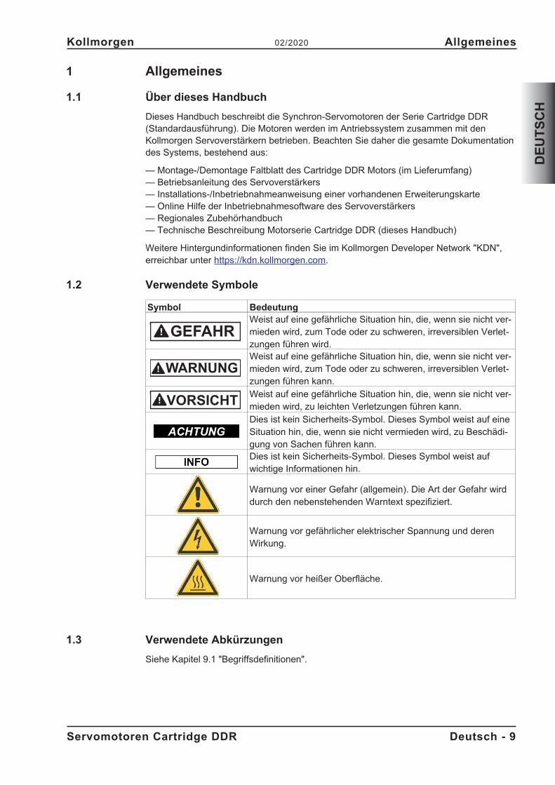
1.2 Verwendete Symbole
Symbol BedeutungWeist auf eine gefährliche Situation hin, die, wenn sie nicht ver-mieden wird, zum Tode oder zu schweren, irreversiblen Verlet-zungen führen wird.Weist auf eine gefährliche Situation hin, die, wenn sie nicht ver-mieden wird, zum Tode oder zu schweren, irreversiblen Verlet-zungen führen kann.Weist auf eine gefährliche Situation hin, die, wenn sie nicht ver-mieden wird, zu leichten Verletzungen führen kann.Dies ist kein Sicherheits-Symbol. Dieses Symbol weist auf eineSituation hin, die, wenn sie nicht vermieden wird, zu Beschädi-gung von Sachen führen kann.Dies ist kein Sicherheits-Symbol. Dieses Symbol weist aufwichtige Informationen hin.
Warnung vor einer Gefahr (allgemein). Die Art der Gefahr wirddurch den nebenstehenden Warntext spezifiziert.
Warnung vor gefährlicher elektrischer Spannung und derenWirkung.
Warnung vor heißer Oberfläche.
1.3 Verwendete Abkürzungen
Siehe Kapitel 9.1 "Begriffsdefinitionen".
Servomotoren Cartridge DDR Deutsch - 9
Kollmorgen 02/2020 Allgemeines
DE
UT
SC
H
GEFAHR
WARNUNG
VORSICHT
2 Sicherheit
2.1 Das sollten Sie beachten
� Der Maschinenhersteller muss eine Gefahrenanalyse für die Maschine erstellen undgeeignete Maßnahmen treffen, dass unvorhergesehene Bewegungen nicht zuSchäden an Personen oder Sachen führen können.
� Nur qualifiziertes Fachpersonal darf Arbeiten wie Transport, Montage und Inbetrieb-nahme ausführen. Qualifiziertes Fachpersonal sind Personen, die mit Transport,Aufstellung, Montage, Inbetriebnahme und Betrieb von Motoren vertraut sind undüber die ihrer Tätigkeit entsprechenden Mindestqualifikationen verfügen:Transport: nur durch Personal mit Kenntnissen in der Behandlung elektro-
statisch gefährdeter BauelementeMech. Installation: nur durch Fachleute mit maschinenbautechnischer
AusbildungElektr. Installation: nur durch Fachleute mit elektrotechnischer AusbildungInbetriebnahme: nur durch Fachleute mit weitreichenden Kenntnissen in
den Bereichen Elektrotechnik / Antriebstechnik� Lesen Sie vor der Montage und Inbetriebnahme die vorliegende Dokumentation.
Falsches Handhaben des Motors kann zu Personen- oder Sachschäden führen.Halten Sie die technischen Daten und die Angaben zu den Anschlussbedingungen(Typenschild und Dokumentation) unbedingt ein.
� Während des Betriebes der Motoren besteht die Gefahr von Tod oder schweren ge-sundheitlichen oder materiellen Schäden. Der Betreiber muss daher sicherstellen,dass die Sicherheitshinweise in diesem Handbuch beachtet werden. Der Betreibermuss sicherstellen, dass alle mit Arbeiten am Motor betrauten Personen das Pro-dukthandbuch gelesen und verstanden haben.
� Heben und bewegen Sie Motoren mit mehr als 20kg Gewicht nur mit Hilfe von He-bevorrichtungen. Heben ohne Hilfsmittel kann zu Rückenverletzungen führen.
Hohe Spannungen
Stellen Sie die ordnungsgemäße Erdung des Motorgehäuses mit der PE-Schiene imSchaltschrank als Bezugspotential sicher. Gefahr durch elektrischen Schlag. Ohne nie-derohmige Erdung ist keine personelle Sicherheit gewährleistet.
Ziehen Sie keine Stecker während des Betriebs. Es besteht die Gefahr von Tod oderschweren gesundheitlichen oder materiellen Schäden beim Berühren freiliegender Kon-takte. Leistungsanschlüsse können Spannung führen, auch wenn sich der Motor nichtdreht. Lösen Sie die elektrischen Anschlüsse der Motoren nie unter Spannung. Inungünstigen Fällen können Lichtbögen entstehen und Personen und Kontakte schädigen.
Warten Sie nach dem Trennen der Servoverstärker von den Versorgungsspannungenmehrere Minuten, bevor Sie spannungsführende Teile (z.B. Kontakte, Gewindebolzen)berühren oder Anschlüsse lösen. Kondensatoren im Servoverstärker führen mehrereMinuten nach Abschalten der Versorgungsspannungen gefährliche Spannungen. MessenSie zur Sicherheit die Spannung im Zwischenkreis und warten Sie, bis die Spannungunter 50V abgesunken ist.
Heiße Oberfläche
Während des Betriebes können Motoren ihrer Schutzart entsprechend heiße Oberflächenbesitzen. Leichte Verbrennungsgefahr!Die Oberflächentemperatur kann 100°C überschreiten. Messen Sie die Temperatur undwarten Sie, bis der Motor auf 40°C abgekühlt ist, bevor Sie ihn berühren
Deutsch - 10 Servomotoren Cartridge DDR
Sicherheit 02/2020 Kollmorgen
DE
UT
SC
H
2.2 Bestimmungsgemäße Verwendung
� Synchron-Servomotoren der Serie Cartridge DDR sind insbesondere als Antrieb fürWalzen in Druckmaschinen, Textilmaschinen, Folienbearbeitungsmaschinen, Verpa-ckungsmaschinen und ähnliche mit hohen Ansprüchen an die Dynamik konzipiert.
� Sie dürfen die Motoren nur unter Berücksichtigung der in dieser Dokumentation de-finierten Umgebungsbedingungen betreiben.
� Die Motoren der Serie Cartridge DDR sind ausschließlich dazu bestimmt, von digi-talen Servoverstärkern drehzahl- und/oder drehmomentgeregelt angesteuert zu wer-den.
� Die Motoren werden als Bauteile in elektrische Anlagen oder Maschinen eingebautund dürfen nur als integrierte Bauteile der Anlage in Betrieb genommen werden.
� Der in die Motorwicklungen eingebaute Temperatursensor muss ausgewertet undüberwacht werden.
� Die Konformität des Servosystems zu den in der EG-Konformitätserklärung (sieheKollmorgen Website) genannten Normen garantieren wir nur, wenn von uns gelie-ferte Komponenten (Servoverstärker, Motor, Leitungen usw.) verwendet werden.
2.3 Nicht bestimmungsgemäße Verwendung
� Der Betrieb der Motoren in folgenden Umgebungen ist verboten:- explosionsgefährdete Bereiche und Umgebungen mit ätzenden und/oder
elektrisch leitenden Säuren, Laugen, Ölen, Dämpfen, Stäuben- direkt am Netz
� Der bestimmungsgemäße Betrieb des Motors ist untersagt, wenn die Maschine, indie er eingebaut wurde,- nicht den Bestimmungen der EG Maschinenrichtlinie entspricht- nicht die Bestimmung der EMV-Richtlinie erfüllt- nicht die Bestimmung der Niederspannungs-Richtlinie erfüllt
Servomotoren Cartridge DDR Deutsch - 11
Kollmorgen 02/2020 Sicherheit
DE
UT
SC
H
3 Handhabung
3.1 Transport
Heben und bewegen Sie Motoren mit mehr als 20kg Gewicht nur mit Hilfe von Hebevor-richtungen. Heben ohne Hilfsmittel kann zu Rückenverletzungen führen.� Transport-Temperatur: -25..+70°C, max. 20K/Stunde schwankend
Transport-Luftfeuchtigkeit: relative Feuchte 5% - 95% nicht kondensierend� Nur von qualifiziertem Personal in der recyclebaren Original-Verpackung des Her-
stellers� Vermeiden Sie harte Stöße� Überprüfen Sie bei beschädigter Verpackung den Motor auf sichtbare Schäden. In-
formieren Sie den Transporteur und gegebenenfalls den Hersteller.
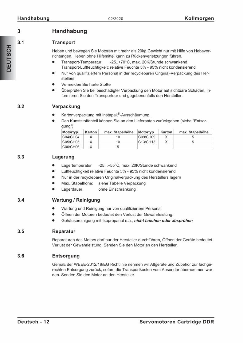
3.2 Verpackung
� Kartonverpackung mit Instapak®-Ausschäumung.� Den Kunststoffanteil können Sie an den Lieferanten zurückgeben (siehe "Entsor-
gung")
Motortyp Karton max. Stapelhöhe Motortyp Karton max. StapelhöheC04/CH04 X 10 C09/CH09 X 5C05/CH05 X 10 C13/CH13 X 5C06/CH06 X 5
3.3 Lagerung
� Lagertemperatur -25...+55°C, max. 20K/Stunde schwankend� Luftfeuchtigkeit relative Feuchte 5% - 95% nicht kondensierend� Nur in der recyclebaren Originalverpackung des Herstellers lagern� Max. Stapelhöhe: siehe Tabelle Verpackung� Lagerdauer: ohne Einschränkung
3.4 Wartung / Reinigung
� Wartung und Reinigung nur von qualifiziertem Personal� Öffnen der Motoren bedeutet den Verlust der Gewährleistung.� Gehäusereinigung mit Isopropanol o.ä., nicht tauchen oder absprühen
3.5 Reparatur
Reparaturen des Motors darf nur der Hersteller durchführen, Öffnen der Geräte bedeutetVerlust der Gewährleistung. Senden Sie den Motor an den Hersteller.
3.6 Entsorgung
Gemäß der WEEE-2012/19/EG Richtlinie nehmen wir Altgeräte und Zubehör zur fachge-rechten Entsorgung zurück, sofern die Transportkosten vom Absender übernommen wer-den. Senden Sie den Motor an den Hersteller.
Deutsch - 12 Servomotoren Cartridge DDR
Handhabung 02/2020 Kollmorgen
DE
UT
SC
H
4 Produktidentifizierung
4.1 Lieferumfang
Sie erhalten einen Karton mit Instapak®-Ausschäumung. Enthalten ist:� Motor der Serie Cartridge DDR� Mounting/Removal Instruction
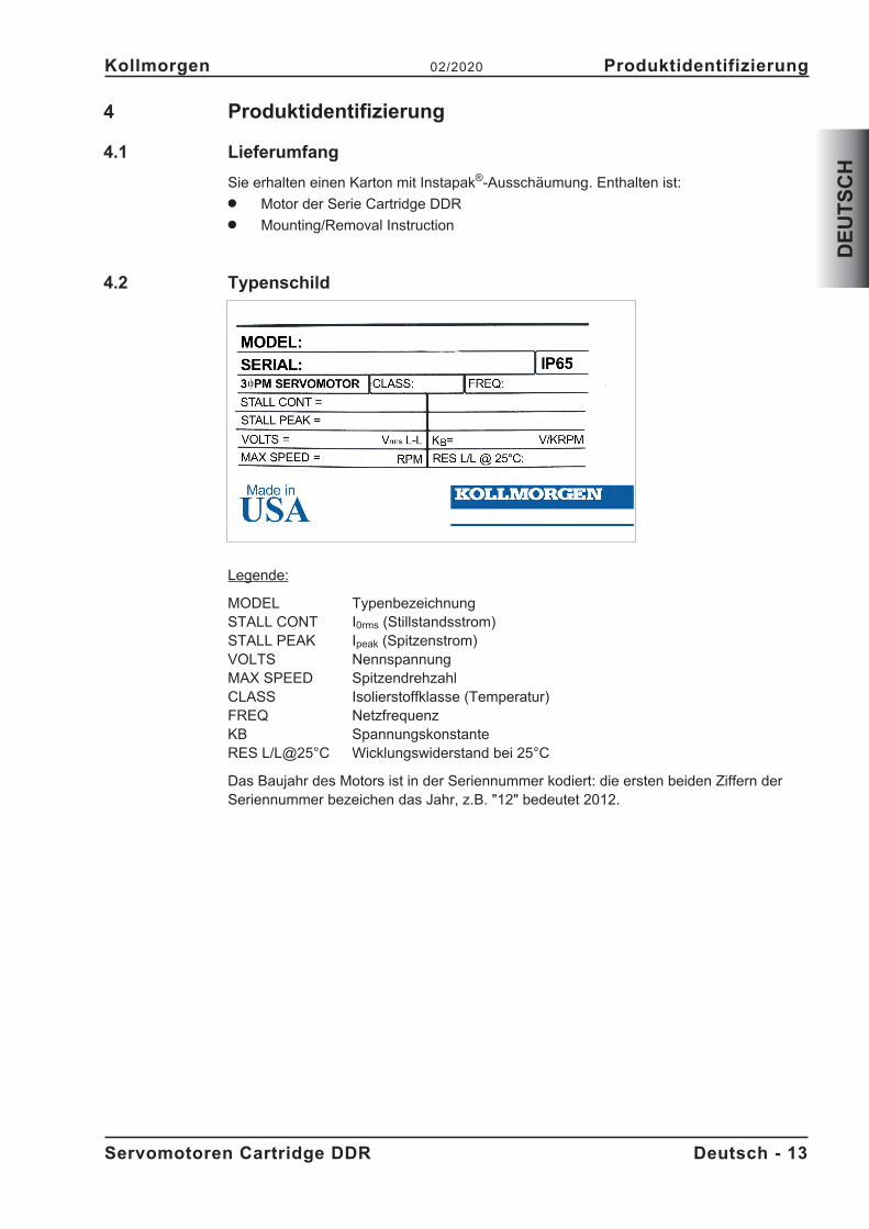
4.2 Typenschild
Legende:
MODEL TypenbezeichnungSTALL CONT I0rms (Stillstandsstrom)STALL PEAK Ipeak (Spitzenstrom)VOLTS NennspannungMAX SPEED SpitzendrehzahlCLASS Isolierstoffklasse (Temperatur)FREQ NetzfrequenzKB SpannungskonstanteRES L/L@25°C Wicklungswiderstand bei 25°C
Das Baujahr des Motors ist in der Seriennummer kodiert: die ersten beiden Ziffern derSeriennummer bezeichen das Jahr, z.B. "12" bedeutet 2012.
Servomotoren Cartridge DDR Deutsch - 13
Kollmorgen 02/2020 Produktidentifizierung
DE
UT
SC
H
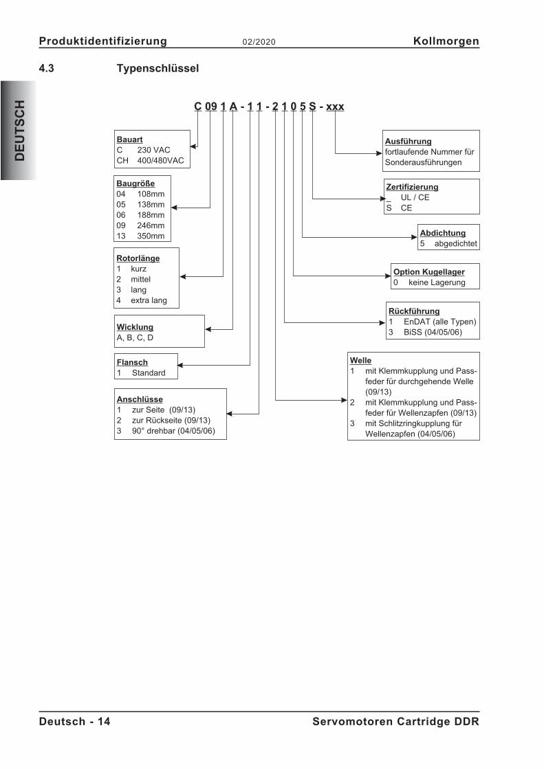
4.3 Typenschlüssel
Deutsch - 14 Servomotoren Cartridge DDR
Produktidentifizierung 02/2020 Kollmorgen
DE
UT
SC
H C 09 1 A - 1 1 - 2 1 0 5 S - xxx
BauartC 230 VACCH 400/480VAC
WicklungA, B, C, D
Baugröße04 108mm05 138mm06 188mm09 246mm13 350mm
Rotorlänge1 kurz2 mittel3 lang4 extra lang
Option Kugellager0 keine Lagerung
Abdichtung5 abgedichtet
Zertifizierung_ UL / CES CE
Ausführungfortlaufende Nummer fürSonderausführungen
Flansch1 Standard
Anschlüsse1 zur Seite (09/13)2 zur Rückseite (09/13)3 90° drehbar (04/05/06)
Rückführung1 EnDAT (alle Typen)3 BiSS (04/05/06)
Welle1 mit Klemmkupplung und Pass-
feder für durchgehende Welle(09/13)
2 mit Klemmkupplung und Pass-feder für Wellenzapfen (09/13)
3 mit Schlitzringkupplung fürWellenzapfen (04/05/06)
5 Technische Beschreibung
5.1 Allgemeine technische Daten
Umgebungstemperatur 5...+40°C bei Aufstellhöhe bis 1000m über NN(bei Nenndaten) Sprechen Sie bei Umgebungstemperaturen über 40°C
und bei gekapseltem Einbau der Motoren unbedingt mitunserer Applikationsabteilung.
Zulässige Luftfeuchte 95% relative Feuchte, nicht betauend(bei Nenndaten)
Leistungsreduzierung 1%/K im Bereich 40°C...50°C bis 1000m über NN(Ströme und Momente) Bei Aufstellhöhen über 1000m über NN und 40°C
6% bei 2000m über NN17% bei 3000m über NN30% bei 4000m über NN55% bei 5000m über NN
Keine Leistungsreduzierung bei Aufstellhöhen über1000m über NN und Temperaturreduzierungum 10K / 1000m
Technische Daten für die Motoren finden Sie in Kapitel "Technical Data" ab S. 73.
5.1.1 Bauform
Der Motor kann in beliebiger Einbaulage, also auch an horizontalen oder vertikalen Wel-len, montiert werden.
5.1.2 Flansch
Die Cartridge DDR besitzen keinen eignen Flansch, sondern werden mit einer Klemm-kupplung und Zentrierring an den Maschinenflansch montiert. Ein Passring am Motordient der Zentrierung am Maschinenflansch, die Klemmkupplung fixiert den integriertenRotor auf der Maschinenwelle. Der Motor besitzt keine eigenen Lager.
Die Anforderungen an den Flansch werden in den Kapiteln 6.2 bzw. 6.3 beschrieben.
Bei den Motoren C(H)09 und C(H)13 ist eine Version mit Hohlwellenöffnung für durchge-hende Motorwellen verfügbar.
Servomotoren Cartridge DDR Deutsch - 15
Kollmorgen 02/2020 Technische Beschreibung
DE
UT
SC
H
5.1.3 Schutzart
Ausführung für Wellenzapfen (2, 3): IP65 bei abgedichtetem MaschinenflanschAusführung mit Hohlwelle (1): IP64 bei abgedichtetem Maschinenflansch
5.1.4 Isolierstoffklasse
Die Motoren entsprechen der Isolierstoffklasse F nach IEC 60085 (UL 1446 class F).
5.1.5 Oberfläche
Die Motoren sind mattschwarz mit Polyester pulverbeschichtet, eine Beständigkeit gegenLösungsmittel (Tri, Verdünnung o.ä.) besteht nicht.
5.1.6 Schutzeinrichtung
In der Standardausführung ist jeder Motor mit einem potentialfreien PTC ausgestattet.
Der Schaltpunkt liegt bei 155°C � 5%. Schutz gegen kurzzeitige, sehr hohe Überlastungbietet der PTC nicht. Der PTC ist bei Verwendung unserer vorkonfektionierten Encoder-leitung in das Überwachungssystem der digitalen Servoverstärker integriert.
5.1.7 Anschlusstechnik
Die Motoren sind mit Steckern für die Leistungsversorgung und die Encodersignale aus-gerüstet. Die Stecker weisen je nach Ausführung entweder zur Seite oder zur Rückseitedes Motors oder sind um 90° drehbar.
Die Gegenstecker gehören nicht zum Lieferumfang. Rückführungs- und Leistungsleitun-gen bieten wir Ihnen fertig konfektioniert an.
5.1.8 Rückführeinheit
C(H) yyxx-xx-x1xxHochauflösender SinCos-Drehgeber, Singleturn, EnDat ECN1313 (2048 Period)
C(H) 04xx-xx-x3xx, C(H) 05xx-xx-x3xx und C(H) 06xx-xx-x3xxHochauflösender SinCos-Drehgeber, Singleturn, Hengstler ACURO AD36 (2048 Period);BiSS
Deutsch - 16 Servomotoren Cartridge DDR
Technische Beschreibung 02/2020 Kollmorgen
DE
UT
SC
H
6 Mechanische Installation
Maßzeichnungen finden Sie im Kapitel "Dimension Drawings" ab S. 79.
6.1 Wichtige Hinweise
Nur Fachleute mit Maschinenbau-Kenntnissen dürfen den Motor montieren.
Montieren Sie die Motoren immer im spannungsfreien Zustand, d.h. keine derBetriebsspannungen einer Komponente der Anlage darf eingeschaltet sein.
Es besteht die Gefahr von Tod oder schweren gesundheitlichen Schäden beimBerühren freiliegender Kontakte.
Sorgen Sie für eine sichere Freischaltung des Schaltschrankes (Sperre,Warnschilder etc.). Erst bei der Inbetriebnahme werden die einzelnenSpannungen eingeschaltet.
Die Montageseite des Motors ist magnetisch und zieht Eisen an. Decken Sie das Endedes Motors ab, wenn der Motor nicht montiert ist, um Verschmutzung zu verhindern.
� Schützen Sie die Motoren vor unzulässiger Beanspruchung.Insbesondere dürfen bei Transport und Handhabung keine Bauelemente verbogenund / oder Isolationsabstände verändert werden
� Der Einbauort muss frei von leitfähigen und aggressiven Stoffen sein.Bei gekapseltem Einbau sollten Sie zunächst mit unserer Applikationsabteilung Rüc-ksprache nehmen.
� Montieren Sie den Motor nach den Anweisungen im "Mounting/Removal" Faltblatt,das dem Motor beiliegt.Achten Sie bei der Montage darauf, dass der Motor nicht mechanisch überbestimmtbefestigt wird.
� Stellen Sie die ungehinderte Belüftung der Motoren sicher und beachten Sie die zu-lässige Umgebungs- und Flanschtemperatur. Bei Umgebungstemperaturen über40°C sollten Sie zunächst mit unserer Applikationsabteilung Rücksprache nehmen.
Servomotoren Cartridge DDR Deutsch - 17
Kollmorgen 02/2020 Mechanische Installation
DE
UT
SC
H
GEFAHR
6.2 Typen C04/CH04, C05/CH05 und C06/CH06
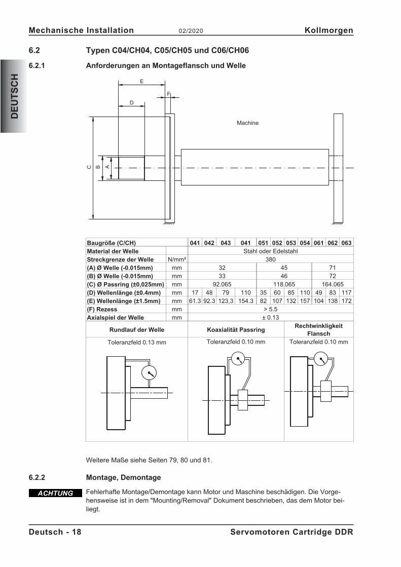
6.2.1 Anforderungen an Montageflansch und Welle
Baugröße (C/CH) 041 042 043 041 051 052 053 054 061 062 063
Material der Welle Stahl oder EdelstahlStreckgrenze der Welle N/mm² 380(A) Ø Welle (-0.015mm) mm 32 45 71(B) Ø Welle (-0.015mm) mm 33 46 72(C) Ø Passring (±0,025mm) mm 92.065 118.065 164.065(D) Wellenlänge (±0.4mm) mm 17 48 79 110 35 60 85 110 49 83 117(E) Wellenlänge (±1.5mm) mm 61.3 92.3 123,3 154.3 82 107 132 157 104 138 172(F) Rezess mm > 5.5Axialspiel der Welle mm ± 0.13
Rundlauf der Welle Koaxialität PassringRechtwinkligkeit
Flansch
Toleranzfeld 0.13 mm Toleranzfeld 0.10 mm Toleranzfeld 0.10 mm
Weitere Maße siehe Seiten 79, 80 und 81.
6.2.2 Montage, Demontage
Fehlerhafte Montage/Demontage kann Motor und Maschine beschädigen. Die Vorge-hensweise ist in dem "Mounting/Removal" Dokument beschrieben, das dem Motor bei-liegt.
Deutsch - 18 Servomotoren Cartridge DDR
Mechanische Installation 02/2020 Kollmorgen
DE
UT
SC
H
BCE
A
F
D
Machine
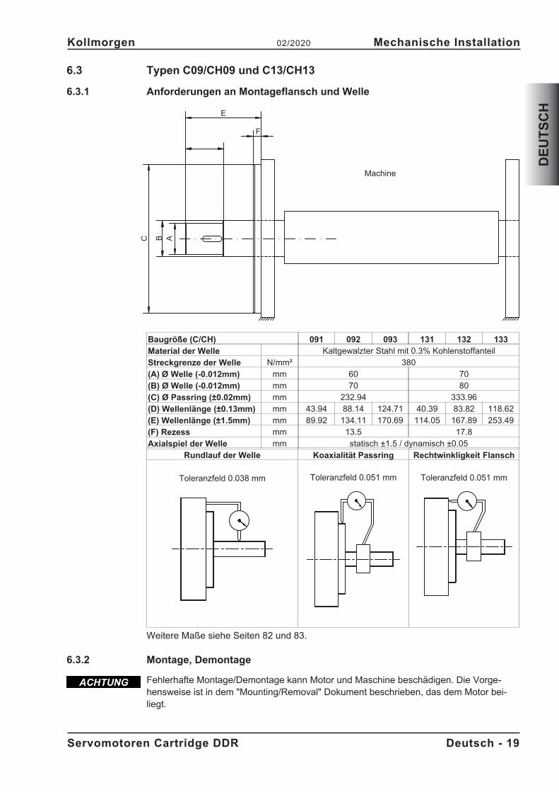
6.3 Typen C09/CH09 und C13/CH13
6.3.1 Anforderungen an Montageflansch und Welle
Baugröße (C/CH) 091 092 093 131 132 133
Material der Welle Kaltgewalzter Stahl mit 0.3% KohlenstoffanteilStreckgrenze der Welle N/mm² 380(A) Ø Welle (-0.012mm) mm 60 70(B) Ø Welle (-0.012mm) mm 70 80(C) Ø Passring (±0.02mm) mm 232.94 333.96(D) Wellenlänge (±0.13mm) mm 43.94 88.14 124.71 40.39 83.82 118.62(E) Wellenlänge (±1.5mm) mm 89.92 134.11 170.69 114.05 167.89 253.49(F) Rezess mm 13.5 17.8Axialspiel der Welle mm statisch ±1.5 / dynamisch ±0.05
Rundlauf der Welle Koaxialität Passring Rechtwinkligkeit Flansch
Toleranzfeld 0.038 mm Toleranzfeld 0.051 mm Toleranzfeld 0.051 mm
Weitere Maße siehe Seiten 82 und 83.
6.3.2 Montage, Demontage
Fehlerhafte Montage/Demontage kann Motor und Maschine beschädigen. Die Vorge-hensweise ist in dem "Mounting/Removal" Dokument beschrieben, das dem Motor bei-liegt.
Servomotoren Cartridge DDR Deutsch - 19
Kollmorgen 02/2020 Mechanische Installation
DE
UT
SC
H
BC
E
A
F
Machine
7 Elektrische Installation
Anschlusspläne finden Sie im Kapitel "Wiring Diagrams" ab S. 84 .
7.1 Wichtige Hinweise
Nur Fachleute mit elektrotechnischer Ausbildung dürfen den Motor verdrahten.
Verdrahten Sie die Motoren immer im spannungsfreien Zustand, d.h. keine derBetriebsspannungen eines anzuschließenden Gerätes darf eingeschaltet sein.Es besteht die Gefahr von Tod oder schweren gesundheitlichen Schäden beimBerühren freiliegender Kontakte.Sorgen Sie für eine sichere Freischaltung des Schaltschrankes (Sperre,Warnschilder etc.). Erst bei der Inbetriebnahme werden die einzelnenSpannungen eingeschaltet.
Lösen Sie die elektrischen Anschlüsse der Motoren nie unter Spannung. Gefahrdurch elektrischen Schlag! In ungünstigen Fällen können Lichtbögen entstehenund Personen und Kontakte schädigen.
Restladungen in den Kondensatoren des Servoverstärkers können bis zu 10Minuten nach Abschalten der Netzspannung gefährliche Werte aufweisen.Leistungsanschlüsse können Spannung führen, auch wenn sich der Motor nichtdreht.
Messen Sie die Spannung im Zwischenkreis und warten Sie, bis die Spannungunter 50V abgesunken ist.
Das Masse-Zeichen�, das Sie in allen Anschlussplänen finden, deutet an, dass Siefür eine möglichst großflächige, elektrisch leitende Verbindung zwischen dem gekenn-zeichneten Gerät und der Montageplatte in Ihrem Schaltschrank sorgen müssen. DieseVerbindung soll die Ableitung von HF-Störungen ermöglichen und ist nicht zu verwech-seln mit dem PE-Zeichen (Schutzmaßnahme nach EN 60204).Beachten Sie auch die Hinweise in den Anschlussplänen in der Betriebsanleitung desverwendeten Servoverstärkers.
7.2 Anschluss der Motoren mit vorkonfektionierten Kabeln
� Führen Sie die Verdrahtung gemäß den geltenden Vorschriften und Normen aus.� Verwenden Sie für Leistungs- und Rückführanschluss ausschließlich vorkonfektio-
nierte, abgeschirmte Leitungen von Kollmorgen.� Nicht korrekt aufgelegte Abschirmungen führen unweigerlich zu EMV-Störungen
und Funktionsbeeintrachtigungen des Systems.� Die maximale Leitungslänge ist in der Betriebsanleitung des verwendeten Servover-
stärkers definiert.
Technische Daten unserer konfektionierten Leitungen finden Sie im Zubehörhandbuch.
Deutsch - 20 Servomotoren Cartridge DDR
Elektrische Installation 02/2020 Kollmorgen
DE
UT
SC
H
GEFAHR
7.3 Leitfaden für die elektrische Installation
� Prüfen Sie die Zuordnung von Servoverstärker und Motor. Vergleichen Sie Nenn-spannung und Nennstrom der Geräte. Führen Sie die Verdrahtung nach dem An-schlussbild in der Betriebsanleitung des Servoverstärkers aus. Die Anschlüsse desMotors sind im Kapitel "Wiring Diagrams" ab S.84 dargestellt.
� Verlegen Sie sämtliche starkstromführenden Leitungen in ausreichendem Quer-schnitt nach EN 60204. Die empfohlenen Querschnitte finden Sie in den techni-schen Daten.
� Abhängig vom Typ des verwendeten Servoverstärkers muss bei langen Motorleitung(> 25m) eine Motordrossel (3YL oder 3YLN) in die Motorleitung geschaltet werden(siehe Betriebsanleitung des Servoverstärkers und Zubehörhandbuch).
� Achten Sie auf einwandfreie Erdung von Servoverstärker und Motor. EMV-gerechteAbschirmung und Erdung siehe Betriebsanleitung des verwendeten Servoverstär-kers. Erden Sie Montageplatte und Motorgehäuse.
� Verdrahtung:— Leistungs- und Steuerkabel möglichst getrennt verlegen— Encoder anschließen— Motorleitungen anschließen, Motordrossel nahe am Servoverstärker— Abschirmungen beidseitig auf Schirmklemmen bzw. EMV-Stecker
� Legen Sie Abschirmungen großflächig (niederohmig) über metallisierte Steckerge-häuse bzw. EMV-gerechte Kabelverschraubungen auf.
� Anforderungen an das Leitungsmaterial:KapazitätMotorleitung: kleiner als 150 pF/mFeedback-Leitung: kleiner als 120 pF/m
Servomotoren Cartridge DDR Deutsch - 21
Kollmorgen 02/2020 Elektrische Installation
DE
UT
SC
H
8 Inbetriebnahme
8.1 Wichtige Hinweise
Nur Fachleute mit weitreichenden Kenntnissen in den Bereichen Elektrotechnik /Antriebs-technik dürfen die Antriebseinheit Servoverstärker/Motor in Betrieb nehmen.
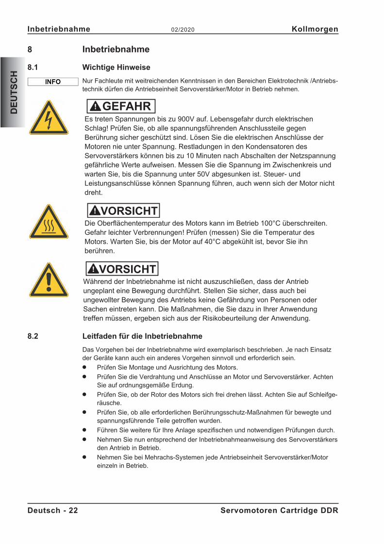
Es treten Spannungen bis zu 900V auf. Lebensgefahr durch elektrischenSchlag! Prüfen Sie, ob alle spannungsführenden Anschlussteile gegenBerührung sicher geschützt sind. Lösen Sie die elektrischen Anschlüsse derMotoren nie unter Spannung. Restladungen in den Kondensatoren desServoverstärkers können bis zu 10 Minuten nach Abschalten der Netzspannunggefährliche Werte aufweisen. Messen Sie die Spannung im Zwischenkreis undwarten Sie, bis die Spannung unter 50V abgesunken ist. Steuer- undLeistungsanschlüsse können Spannung führen, auch wenn sich der Motor nichtdreht.
Die Oberflächentemperatur des Motors kann im Betrieb 100°C überschreiten.Gefahr leichter Verbrennungen! Prüfen (messen) Sie die Temperatur desMotors. Warten Sie, bis der Motor auf 40°C abgekühlt ist, bevor Sie ihnberühren.
Während der Inbetriebnahme ist nicht auszuschließen, dass der Antriebungeplant eine Bewegung durchführt. Stellen Sie sicher, dass auch beiungewollter Bewegung des Antriebs keine Gefährdung von Personen oderSachen eintreten kann. Die Maßnahmen, die Sie dazu in Ihrer Anwendungtreffen müssen, ergeben sich aus der Risikobeurteilung der Anwendung.
8.2 Leitfaden für die Inbetriebnahme
Das Vorgehen bei der Inbetriebnahme wird exemplarisch beschrieben. Je nach Einsatzder Geräte kann auch ein anderes Vorgehen sinnvoll und erforderlich sein.� Prüfen Sie Montage und Ausrichtung des Motors.� Prüfen Sie die Verdrahtung und Anschlüsse an Motor und Servoverstärker. Achten
Sie auf ordnungsgemäße Erdung.� Prüfen Sie, ob der Rotor des Motors sich frei drehen lässt. Achten Sie auf Schleifge-
räusche.� Prüfen Sie, ob alle erforderlichen Berührungsschutz-Maßnahmen für bewegte und
spannungsführende Teile getroffen wurden.� Führen Sie weitere für Ihre Anlage spezifischen und notwendigen Prüfungen durch.� Nehmen Sie nun entsprechend der Inbetriebnahmeanweisung des Servoverstärkers
den Antrieb in Betrieb.� Nehmen Sie bei Mehrachs-Systemen jede Antriebseinheit Servoverstärker/Motor
einzeln in Betrieb.
Deutsch - 22 Servomotoren Cartridge DDR
Inbetriebnahme 02/2020 Kollmorgen
DE
UT
SC
H
GEFAHR
VORSICHT
VORSICHT
8.3 Beseitigen von Störungen
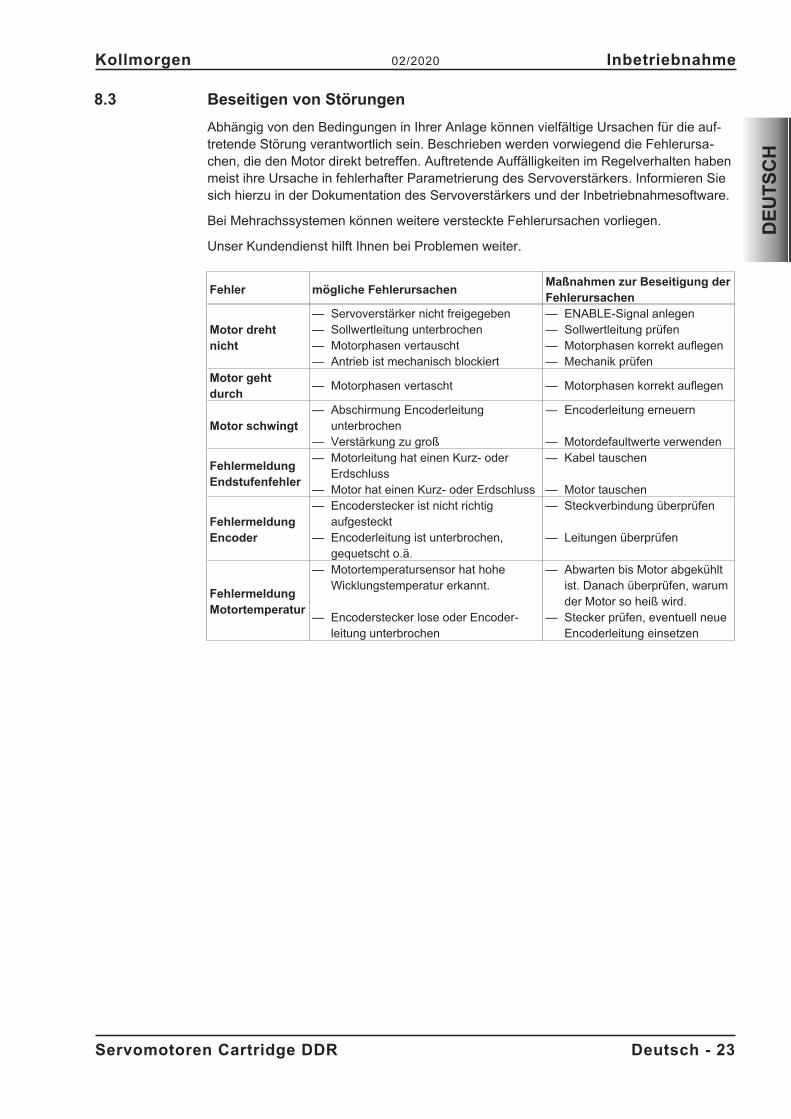
Abhängig von den Bedingungen in Ihrer Anlage können vielfältige Ursachen für die auf-tretende Störung verantwortlich sein. Beschrieben werden vorwiegend die Fehlerursa-chen, die den Motor direkt betreffen. Auftretende Auffälligkeiten im Regelverhalten habenmeist ihre Ursache in fehlerhafter Parametrierung des Servoverstärkers. Informieren Siesich hierzu in der Dokumentation des Servoverstärkers und der Inbetriebnahmesoftware.
Bei Mehrachssystemen können weitere versteckte Fehlerursachen vorliegen.
Unser Kundendienst hilft Ihnen bei Problemen weiter.
Fehler mögliche FehlerursachenMaßnahmen zur Beseitigung derFehlerursachen
Motor drehtnicht
— Servoverstärker nicht freigegeben— Sollwertleitung unterbrochen— Motorphasen vertauscht— Antrieb ist mechanisch blockiert
— ENABLE-Signal anlegen— Sollwertleitung prüfen— Motorphasen korrekt auflegen— Mechanik prüfen
Motor gehtdurch
— Motorphasen vertascht — Motorphasen korrekt auflegen
Motor schwingt— Abschirmung Encoderleitung
unterbrochen— Verstärkung zu groß
— Encoderleitung erneuern
— Motordefaultwerte verwenden
FehlermeldungEndstufenfehler
— Motorleitung hat einen Kurz- oderErdschluss
— Motor hat einen Kurz- oder Erdschluss
— Kabel tauschen
— Motor tauschen
FehlermeldungEncoder
— Encoderstecker ist nicht richtigaufgesteckt
— Encoderleitung ist unterbrochen,gequetscht o.ä.
— Steckverbindung überprüfen
— Leitungen überprüfen
FehlermeldungMotortemperatur
— Motortemperatursensor hat hoheWicklungstemperatur erkannt.
— Encoderstecker lose oder Encoder-leitung unterbrochen
— Abwarten bis Motor abgekühltist. Danach überprüfen, warumder Motor so heiß wird.
— Stecker prüfen, eventuell neueEncoderleitung einsetzen
Servomotoren Cartridge DDR Deutsch - 23
Kollmorgen 02/2020 Inbetriebnahme
DE
UT
SC
H
9 Technische Daten
Technische Daten zu jedem Motortyp finden Sie im Kapitel "Technical Data" ab Seite 73.
Alle Angaben bei 40°C Umgebungstemperatur und 100K Wicklungsübertemperatur.Die Daten können eine Toleranz von +/- 10% aufweisen.
9.1 Begriffsdefinitionen
Stillstandsdrehmoment M0 [Nm]Das Stillstandsdrehmoment kann bei Drehzahl 0<n<100 min-1 und Nenn-Umgebungsbe-dingungen unbegrenzt lange abgegeben werden.
Nenndrehmoment Mn [Nm]Das Nenndrehmoment wird abgegeben, wenn der Motor bei Nenndrehzahl Nennstromaufnimmt. Das Nenndrehmoment kann im Dauerbetrieb (S1) bei Nenndrehzahl unbe-grenzt lange abgegeben werden.
Stillstandsstrom I0rms [A]Der Stillstandsstrom ist der Sinus-Effektiv-Stromwert, den der Motor bei 0<n<100 min-1
aufnimmt, um das Stillstandsdrehmoment abgeben zu können.
Spitzenstrom (Impulsstrom) I0max [A]Der Spitzenstrom (Sinus-Effektivwert) entspricht ca. dem 3-fachen Stillstandsstrom.Der Spitzenstrom des verwendeten Servoverstärkers muss kleiner sein.
Drehmomentkonstante KTrms [Nm/A]Die Drehmomentkonstante gibt an, wie viel Drehmoment in Nm der Motor mit 1ASinus-Effektivstrom erzeugt. Es gilt M=I x KT (bis maximal I = 2 x I0)
Spannungskonstante KErms [mVmin]Die Spannungskonstante gibt die auf 1000U/min bezogene induzierte Motor EMK alsSinus-Effektivwert zwischen zwei Klemmen an.
Rotorträgheitsmoment J [kgcm²]Die Konstante J ist ein Maß für das Beschleunigungsvermögen des Motors. Mit I0 ergibtsich z.B. die Beschleunigungszeit tb von 0 bis 3000 min-1 zu :
t sM s
m
cmJ
b[ ] �
�
��
��
3000 2
60 100
2
4 2
�mit M0 in Nm und J in kgcm²
Thermische Zeitkonstante tth [min]Die Konstante tth gibt die Erwärmungszeit des kalten Motors bei Belastung mit I0 bis zumErreichen von 0,63 x 100 Kelvin Übertemperatur an.Bei Belastung mit Spitzenstrom erfolgt die Erwärmung in wesentlich kürzerer Zeit.
UN
Netznennspannung
Un
Zwischenkreisspannung. U Un N
� �2
Deutsch - 24 Servomotoren Cartridge DDR
Technische Daten 02/2020 Kollmorgen
DE
UT
SC
H
10 General
10.1 About this manual
This manual describes the Cartridge DDR series of synchronous servomotors (standardversion).
The motors are operated in drive systems together with Kollmorgen servo amplifiers.Please observe the entire system documentation, consisting of:
— Cartridge DDR motor mounting/removal instructions (part of delivery)— Instructions manual for the servo amplifier— Installation and setup instructions for any expansion card which is connected— Online help of the amplifier's setup software— Regional Accessories manual— Technical description of the Cartridge DDR series of motors
More background information can be found in our Kollmorgen Developer Network "KDN",available at https://kdn.kollmorgen.com.
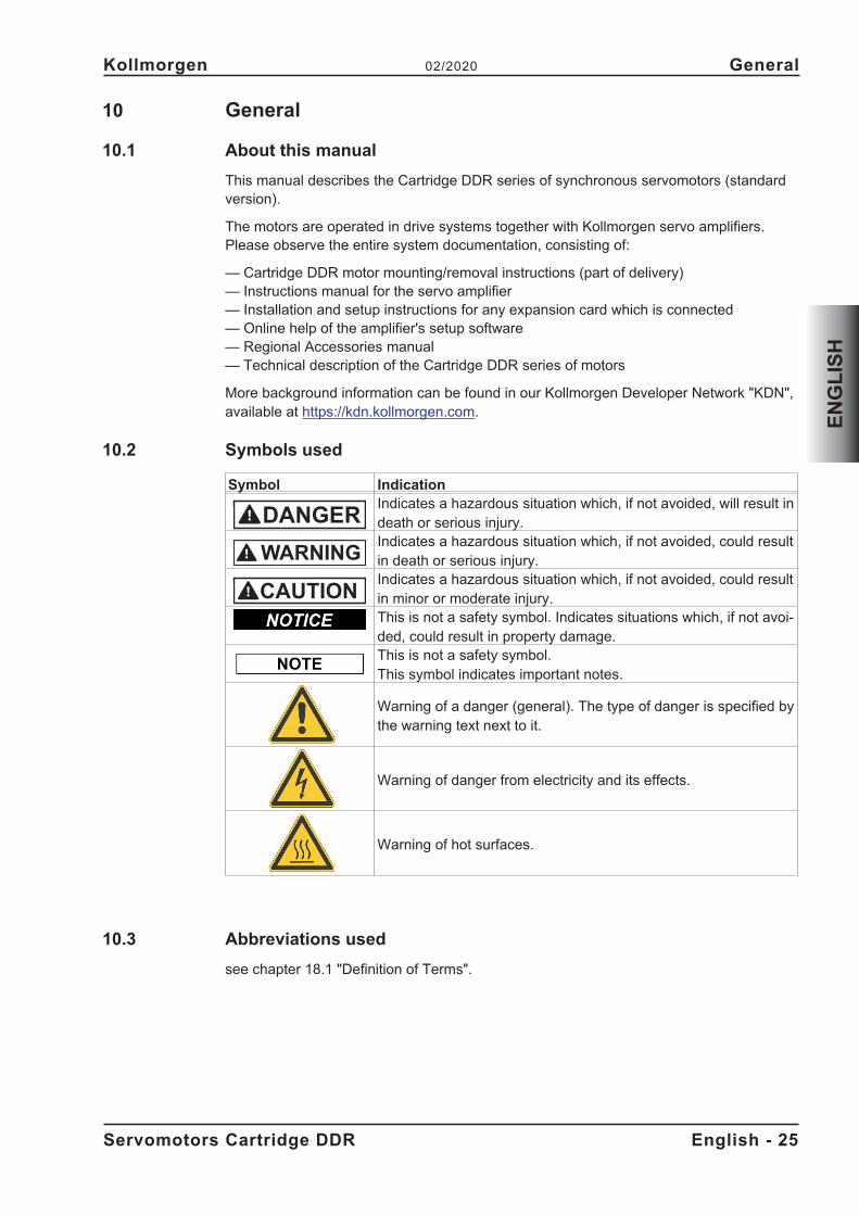
10.2 Symbols used
Symbol IndicationIndicates a hazardous situation which, if not avoided, will result indeath or serious injury.Indicates a hazardous situation which, if not avoided, could resultin death or serious injury.Indicates a hazardous situation which, if not avoided, could resultin minor or moderate injury.This is not a safety symbol. Indicates situations which, if not avoi-ded, could result in property damage.This is not a safety symbol.This symbol indicates important notes.
Warning of a danger (general). The type of danger is specified bythe warning text next to it.
Warning of danger from electricity and its effects.
Warning of hot surfaces.
10.3 Abbreviations used
see chapter 18.1 "Definition of Terms".
Servomotors Cartridge DDR English - 25
Kollmorgen 02/2020 General
EN
GL
ISH
DANGER
WARNING
CAUTION
11 Safety
11.1 You should pay attention to this
� The manufacturer of the machine must generate a hazard analysis for the machine,and take appropriate measures to ensure that unforeseen movements cannot causeinjury or damage to any person or property.
� Only properly qualified personnel are permitted to perform such tasks as transport,assembly, setup and maintenance. Qualified specialist staff are persons who are fa-miliar with the transport, installation, assembly, commissioning and operation of dri-ves and who bring their relevant minimum qualifications to bear on their duties:Transport : only by personnel with knowledge of handling electrostati-
cally sensitive components.Mech. Installation : only by mechanically qualified personnel.Electr. Installation : only by electrically qualified personnel.Setup : only by qualified personnel with extensive knowledge of
electrical engineering and drive technology� Read the available documentation before assembly and setup. Incorrect handling of
the motors can result in injury and damage to persons and machinery. Keep strictlyto the technical data and the information on the connection requirements (nameplateand documentation).
� During motor operation, there is a danger of death, severe injury or material dama-ge. The operator must therefore ensure that all persons entrusted to work on themotor have read and understood the manual and that the safety notices in this ma-nual are observed.
� Lift and move motors with more than 20kg weight only with lifting tools. Lifting unas-sisted could result in back injury.
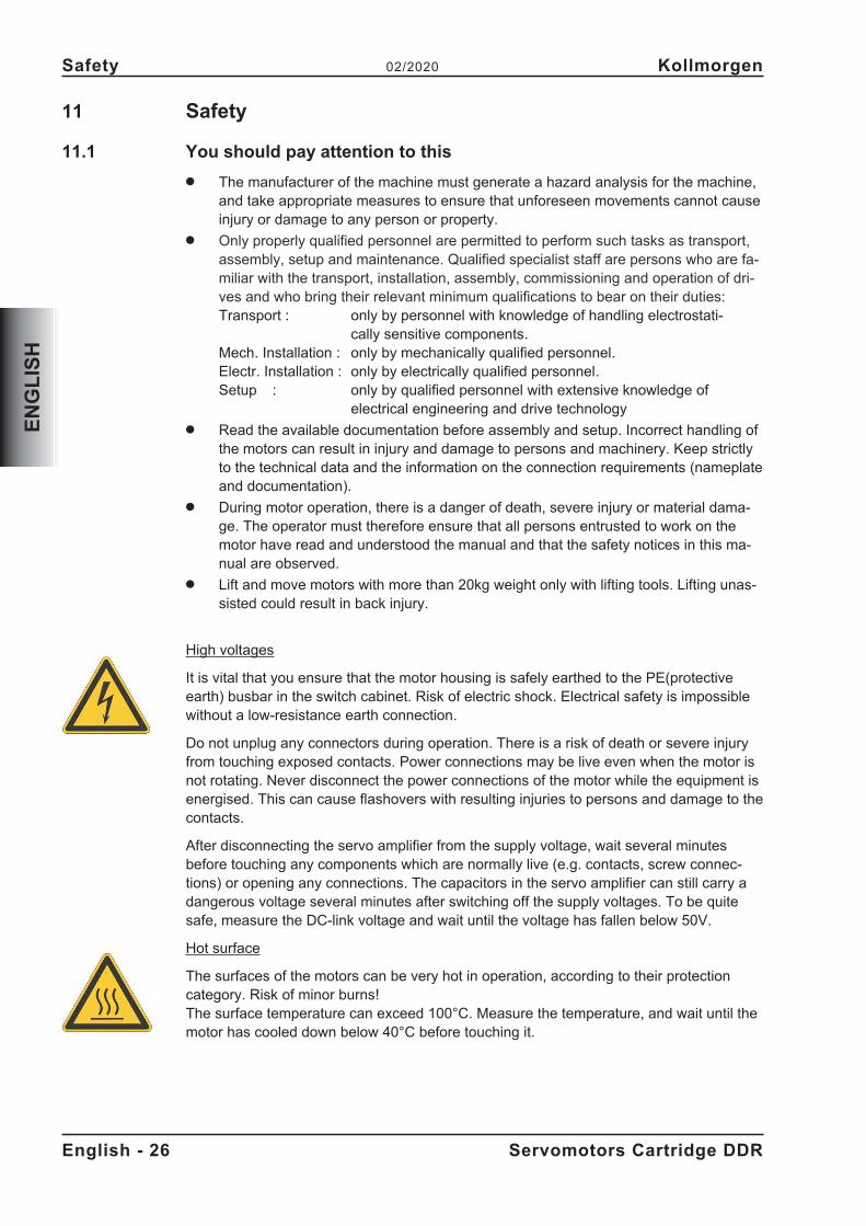
High voltages
It is vital that you ensure that the motor housing is safely earthed to the PE(protectiveearth) busbar in the switch cabinet. Risk of electric shock. Electrical safety is impossiblewithout a low-resistance earth connection.
Do not unplug any connectors during operation. There is a risk of death or severe injuryfrom touching exposed contacts. Power connections may be live even when the motor isnot rotating. Never disconnect the power connections of the motor while the equipment isenergised. This can cause flashovers with resulting injuries to persons and damage to thecontacts.
After disconnecting the servo amplifier from the supply voltage, wait several minutesbefore touching any components which are normally live (e.g. contacts, screw connec-tions) or opening any connections. The capacitors in the servo amplifier can still carry adangerous voltage several minutes after switching off the supply voltages. To be quitesafe, measure the DC-link voltage and wait until the voltage has fallen below 50V.
Hot surface
The surfaces of the motors can be very hot in operation, according to their protectioncategory. Risk of minor burns!The surface temperature can exceed 100°C. Measure the temperature, and wait until themotor has cooled down below 40°C before touching it.
English - 26 Servomotors Cartridge DDR
Safety 02/2020 Kollmorgen
EN
GL
ISH
11.2 Use as directed
� Synchronous servomotors of the Cartridge DDR series are predominantly designedto be used as drives for rollers in printing presses, textile, foil processing and packa-ging machines, as well as similar machines that make high demands on dynamics.
� The user is only permitted to operate the motors under the ambient conditionswhich are defined in this documentation.
� The Cartridge DDR series of motors is exclusively intended to be driven by servoamplifiers under speed and / or torque control.
� The motors are installed as components in electrical apparatus or machines and canonly be commissioned and put into operation as integral components of such appa-ratus or machines.
� The thermal sensor which is integrated in the motor windings must be observed andevaluated.
� The conformity of the servo system to the standards mentioned in the EC Declarati-on of Conformity (see Kollmorgen Website) only guaranteed when the components(servo amplifier, motor, cables etc.) that are used have been supplied by us.
11.3 Prohibited use
� The use of the motors in the following environments is prohibited:- potentially explosive areas- environments with corrosive and/or electrically conductive acids, alkaline solutions,oils, vapours, dusts
- directly on supply networks� Commissioning the motor is prohibited if the machine in which it was installed
- does not meet the requirements of the EC Machinery Directive- does not comply with the EMC Directive- does not comply with the Low Voltage Directive
Servomotors Cartridge DDR English - 27
Kollmorgen 02/2020 Safety
EN
GL
ISH
12 Handling
12.1 Transport
Lift and move motors with more than 20kg weight only with lifting tools. Lifting unassistedcould result in back injury.� Transport temperature -25...+70°C, max. 20K/hr change� Transport humidity rel. humidity 5% - 95% , no condensation� Only by qualified personnel in the manufacturer’s original recyclable packaging� Avoid shocks� If the packaging is damaged, check the motor for visible damage. Inform the carrier
and, if appropriate, the manufacturer.
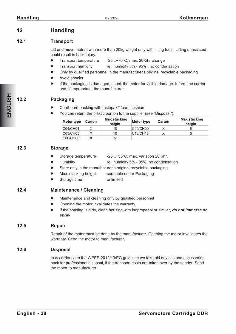
12.2 Packaging
� Cardboard packing with Instapak® foam cushion.� You can return the plastic portion to the supplier (see "Disposal").
Motor type CartonMax.stacking
heightMotor type Carton
Max.stackingheight
C04/CH04 X 10 C09/CH09 X 5C05/CH05 X 10 C13/CH13 X 5C06/CH06 X 5
12.3 Storage
� Storage temperature -25...+55°C, max. variation 20K/hr.� Humidity rel. humidity 5% - 95%, no condensation� Store only in the manufacturer’s original recyclable packaging� Max. stacking height see table under Packaging� Storage time unlimited
12.4 Maintenance / Cleaning
� Maintenance and cleaning only by qualified personnel� Opening the motor invalidates the warranty.� If the housing is dirty, clean housing with Isopropanol or similar, do not immerse or
spray
12.5 Repair
Repair of the motor must be done by the manufacturer. Opening the motor invalidates thewarranty. Send the motor to manufacturer.
12.6 Disposal
In accordance to the WEEE-2012/19/EG guideline we take old devices and accessoriesback for professional disposal, if the transport costs are taken over by the sender. Sendthe motor to manufacturer.
English - 28 Servomotors Cartridge DDR
Handling 02/2020 Kollmorgen
EN
GL
ISH
13 Package
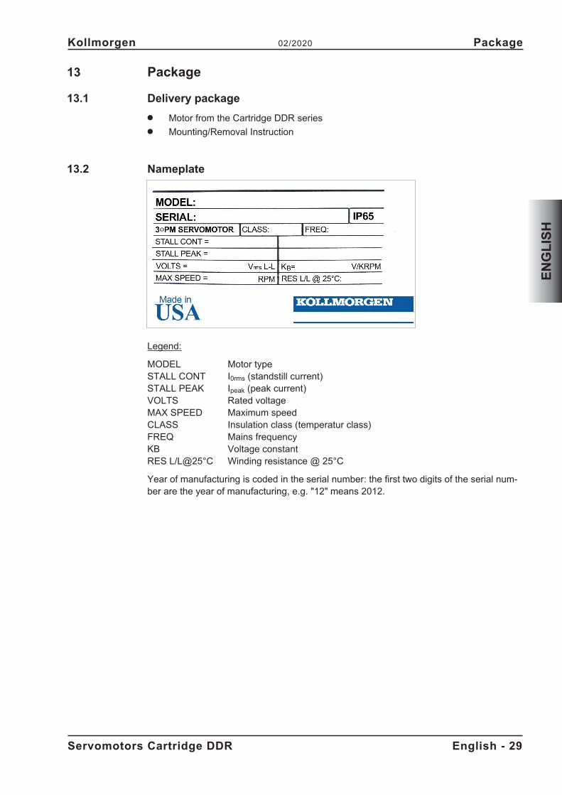
13.1 Delivery package
� Motor from the Cartridge DDR series� Mounting/Removal Instruction
13.2 Nameplate
Legend:
MODEL Motor typeSTALL CONT I0rms (standstill current)STALL PEAK Ipeak (peak current)VOLTS Rated voltageMAX SPEED Maximum speedCLASS Insulation class (temperatur class)FREQ Mains frequencyKB Voltage constantRES L/L@25°C Winding resistance @ 25°C
Year of manufacturing is coded in the serial number: the first two digits of the serial num-ber are the year of manufacturing, e.g. "12" means 2012.
Servomotors Cartridge DDR English - 29
Kollmorgen 02/2020 Package
EN
GL
ISH
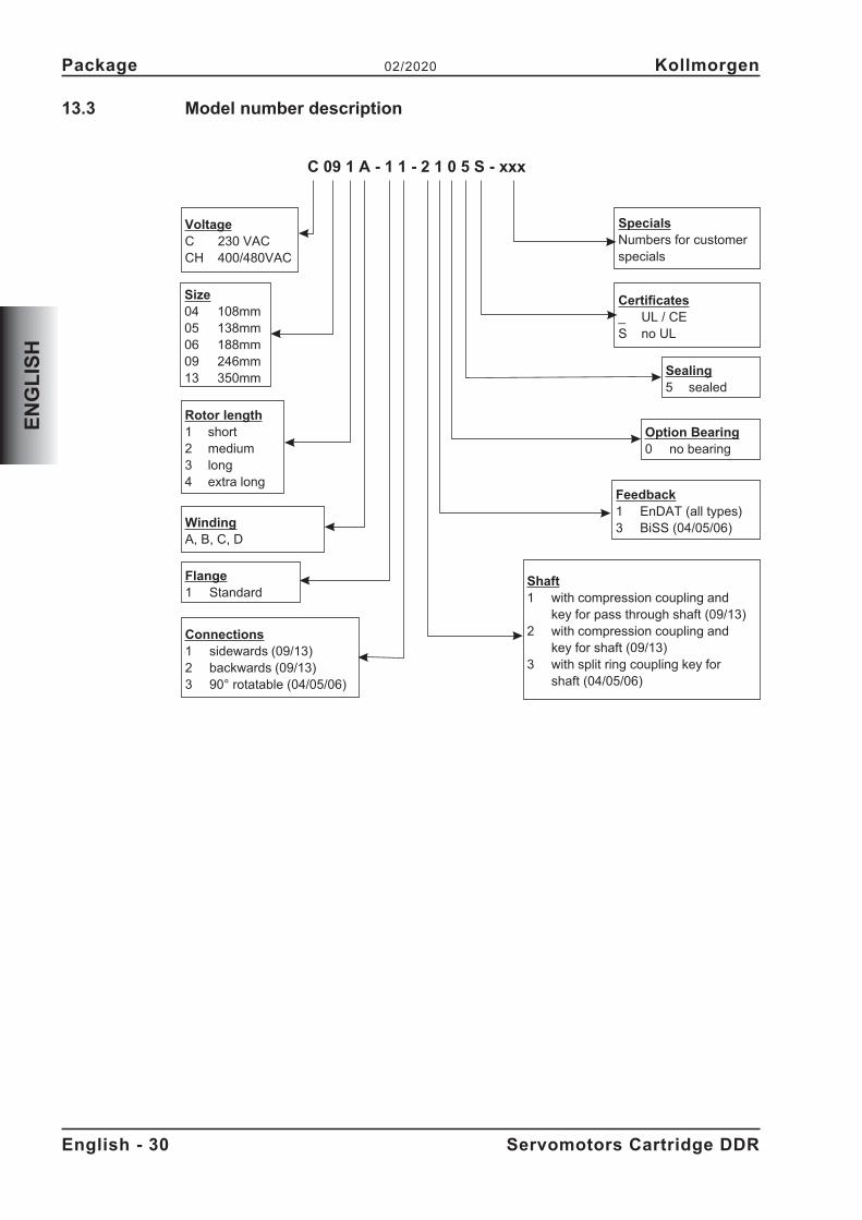
13.3 Model number description
English - 30 Servomotors Cartridge DDR
Package 02/2020 Kollmorgen
EN
GL
ISH
C 09 1 A - 1 1 - 2 1 0 5 S - xxx
VoltageC 230 VACCH 400/480VAC
WindingA, B, C, D
Size04 108mm05 138mm06 188mm09 246mm13 350mm
Rotor length1 short2 medium3 long4 extra long
Option Bearing0 no bearing
Sealing5 sealed
Certificates_ UL / CES no UL
SpecialsNumbers for customerspecials
Flange1 Standard
Connections1 sidewards (09/13)2 backwards (09/13)3 90° rotatable (04/05/06)
Feedback1 EnDAT (all types)3 BiSS (04/05/06)
Shaft1 with compression coupling and
key for pass through shaft (09/13)2 with compression coupling and
key for shaft (09/13)3 with split ring coupling key for
shaft (04/05/06)
14 Technical Description
14.1 General technical data
Ambient temperature 5...+40°C for site altitude up to 1000m amsl(at rated values) It is vital to consult our applications department for
ambient temperatures above 40°C and encapsulatedmounting of the motors.
Permissible humidity 95% rel. humidity, no condensation(at rated values)
Power derating 1% / K in range 40°C...50°C up to 1000m amsl(currents and torques) for site altitude above 1000m amsl and 40°C
6% up to 2000m amsl17% up to 3000m amsl30% up to 4000m amsl55% up to 5000m amsl
No derating for site altitudes above 1000m amslwith temperature reduction of 10K / 1000m
Technical motor data can be found in chapter "Technical Data" from p. 73.
14.1.1 Design
The motor can be installed in any mounting position, including mounting on horizontal orvertical shafts.
14.1.2 Flange
The Cartridge DDR do not have their own flange, instead they are mounted to themachine flange using a compression coupling and centring ring. An adapter ring on themotor is used for centring on the machine flange, while the compression coupling securesthe integrated rotor on the machine shaft. The motor does not have its own bearings.
Requirements relating to the flange are described in chapters 15.2 and 15.3.
For motors C(H)09 and C(H)13, a version is available with hollow shaft openings for con-tinuous motor shafts.
Servomotors Cartridge DDR English - 31
Kollmorgen 02/2020 Technical Description
EN
GL
ISH
14.1.3 Protection class
Version for shaft pegs (2, 3): IP65 for sealed machine flangeVersion with hollow shaft (1): IP64 for sealed machine flange
14.1.4 Insulation material class
The motors come up to insulation material class F according to IEC 60085 (UL 1446class F).
14.1.5 Surface
The motors are coated with polyester powder coating in matt black. This finish is notresistant against solvents (e.g. trichlorethylene, nitro-thinners, or similar).
14.1.6 Protective device
The standard version of each motor is fitted with an electrically isolated PTC (rated tem-
perature 155°C � 5%). The PTC does not provide any protection against short, heavyoverloading. Provided that our preassembled Encoder cable is used, the PTC is integra-ted into the monitoring system of the digital servo amplifiers.
14.1.7 Connection method
The motors are equipped with connectors for the power supply and encoder signals.Depending on the version, the connectors are allocated to either the side or rear of themotor, or they can be rotated by 90°.
The mating connectors are not included in the scope of supply. Feedback cables andpower cables are provided pre-assembled.
14.1.8 Feedback
C(H) yyxx-xx-x1xxHigh resolution SinCos encoder, single turn, ECN1313 (2048 period), EnDat
C(H) 04xx-xx-x3xx, C(H) 05xx-xx-x3xx und C(H) 06xx-xx-x3xxHigh resolution SinCos encoder, single turn, Hengstler ACURO AD36 (2048 period),BiSS
English - 32 Servomotors Cartridge DDR
Technical Description 02/2020 Kollmorgen
EN
GL
ISH
15 Mechanical Installation
Dimension drawings can be found in chapter "Dimension Drawings" from p. 79.
15.1 Important Notes
Only qualified staff with knowledge of mechanical engineering are permitted to assemblethe motor.
Always make sure that the motors are de-energized during assembly andwiring, i.e. no voltage may be switched on for any piece of equipment which isto be connected.
There is a risk of death or severe injury from touching exposed contacts.
Ensure that the switch cabinet remains turned off (barrier, warning signs etc.).The individual voltages will only be turned on again during setup.
The mounting end of the motor is magnetized and will attract magnetic material. If themotor is not mounted, this end of the motor must be covered to insure proper cleanliness.
� Protect the motor from unacceptable stresses.Take care, especially during transport and handling, that components are not bentand that insulation clearances are not altered.
� The site must be free of conductive and aggressive material. If an encapsulated as-sembly is required, please consult our applications department beforehand.
� Assemble the motor according to the instructions on page 34When assembling, ensure that the fastening of the motor is not mechanically over-determined.
� Ensure an unhindered ventilation of the motors and observe the permissible ambientand flange temperatures. For ambient temperatures above 40°C please consult ourapplications department beforehand.
Servomotors Cartridge DDR English - 33
Kollmorgen 02/2020 Mechanical Installation
EN
GL
ISH
DANGER
15.2 Types C04/CH04, C05/CH05 and C06/CH06
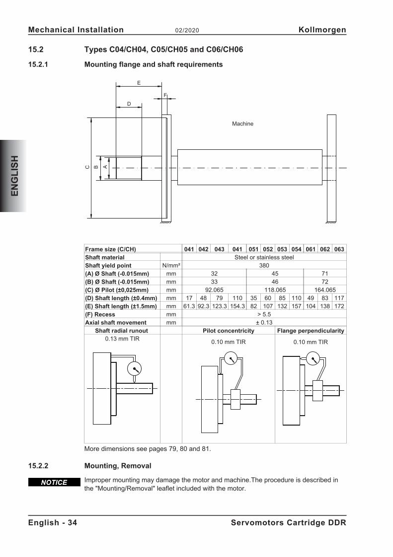
15.2.1 Mounting flange and shaft requirements
Frame size (C/CH) 041 042 043 041 051 052 053 054 061 062 063
Shaft material Steel or stainless steelShaft yield point N/mm² 380(A) Ø Shaft (-0.015mm) mm 32 45 71(B) Ø Shaft (-0.015mm) mm 33 46 72(C) Ø Pilot (±0,025mm) mm 92.065 118.065 164.065(D) Shaft length (±0.4mm) mm 17 48 79 110 35 60 85 110 49 83 117(E) Shaft length (±1.5mm) mm 61.3 92.3 123.3 154.3 82 107 132 157 104 138 172(F) Recess mm > 5.5Axial shaft movement mm ± 0.13
Shaft radial runout Pilot concentricity Flange perpendicularity0.13 mm TIR 0.10 mm TIR 0.10 mm TIR
More dimensions see pages 79, 80 and 81.
15.2.2 Mounting, Removal
Improper mounting may damage the motor and machine.The procedure is described inthe "Mounting/Removal" leaflet included with the motor.
English - 34 Servomotors Cartridge DDR
Mechanical Installation 02/2020 Kollmorgen
EN
GL
ISH
BCE
A
F
D
Machine
15.3 Types C09/CH09 and C13/CH13
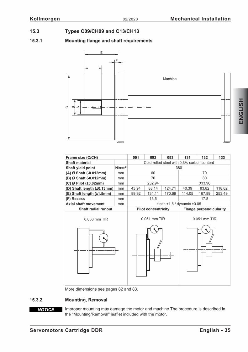
15.3.1 Mounting flange and shaft requirements
Frame size (C/CH) 091 092 093 131 132 133
Shaft material Cold-rolled steel with 0.3% carbon contentShaft yield point N/mm² 380(A) Ø Shaft (-0.012mm) mm 60 70(B) Ø Shaft (-0.012mm) mm 70 80(C) Ø Pilot (±0.02mm) mm 232.94 333.96(D) Shaft length (±0.13mm) mm 43.94 88.14 124.71 40.39 83.82 118.62(E) Shaft length (±1.5mm) mm 89.92 134.11 170.69 114.05 167.89 253.49(F) Recess mm 13.5 17.8Axial shaft movement mm static ±1.5 / dynamic ±0.05
Shaft radial runout Pilot concentricity Flange perpendicularity
0.038 mm TIR 0.051 mm TIR 0.051 mm TIR
More dimensions see pages 82 and 83.
15.3.2 Mounting, Removal
Improper mounting may damage the motor and machine.The procedure is described inthe "Mounting/Removal" leaflet included with the motor.
Servomotors Cartridge DDR English - 35
Kollmorgen 02/2020 Mechanical Installation
EN
GL
ISH
BC
E
A
F
Machine
16 Electrical Installation
Wiring diagrams can be found in chapter "Wiring Diagrams" from p. 84.
16.1 Important notes
Only staff qualified and trained in electrical engineering are allowed to wire up the motor.
Always make sure that the motors are de-energized during assembly andwiring, i.e. no voltage may be switched on for any piece of equipment which isto be connected.
There is a risk of death or severe injury from touching exposed contacts.
Ensure that the switch cabinet remains turned off (barrier, warning signs etc.).The individual voltages will only be turned on again during setup.
Never undo the electrical connections to the motor while it is energized. Risk ofelectric shock! In unfavorable circumstances, electric arcs can arise causingharm to people and damaging contacts.
A dangerous voltage, resulting from residual charge, can be still present on thecapacitors up to 10 minutes after switch-off of the mains supply. Even when themotor is not rotating, control and power leads may be live. Measure the DC-linkvoltage and wait until it has fallen below 50V.
The ground symbol�, which you will find in the wiring diagrams, indicates that youmust provide an electrical connection, with as large a surface area as possible, betweenthe unit indicated and the mounting plate in the switch cabinet. This connection is to sup-press HF interference and must not be confused with the PE (protective earth) symbol(protective measure to EN 60204).
To wire up the motor, use the wiring diagrams in the Installation and Setup Instructions ofthe servo amplifier which is used.
16.2 Connection of the motors with preassembled cables
� Carry out the wiring in accordance with the valid standards and regulations.� Only use Kollmorgen preassembled shielded cables for the feedback and power
connections.� Incorrectly installed shielding leads to EMC interference and has an adverse effect
on system function.� The maximum cable length is defined in the instructions manual of the used servo
amplifier.
For a detailed description of preassembled cables, please refer to the accessoriesmanual.
English - 36 Servomotors Cartridge DDR
Electrical Installation 02/2020 Kollmorgen
EN
GL
ISH
DANGER
16.3 Guide for electrical installation
� Check that the servo amplifier and motor match each other. Compare the rated vol-tage and rated current of the unit. Carry out the wiring according to the wiring dia-gram in the instructions manual of the servo amplifier. The connections to the motorare shown in chapter "Wiring Diagrams" from p.84.
� Install all cables carrying a heavy current with an adequate cross-section, as perEN 60204. The recommended cross-section can be found in the technical data.
� In case of long motor cables (>25m) and dependent on the type of the used servoamplifier a motor choke (3YL or 3YLN) must be switched into the motor cable (seeinstructions manual of the servo amplifier and accessory manual).
� Ensure that there is proper earthing of the servo amplifier and the motor. Use correctearthing and EMC-shielding according to the instructions manual of the servo ampli-fier which is used. Earth the mounting plate and motor casing.
� Cabling:— Route power cables as separately as possible from control cables— Connect up the Encoder.— Connect the motor cables, install motor chokes close to the servo
amplifier— Connect shields to shielding terminals or EMC connectors at both ends.
� Connect up all shielding via a wide surface-area contact (low impedance) and me-tallized connector housings or EMC-cable glands.
� Requirements to cable material:CapacityMotor cable less than 150 pF/mFeedback cable less than 120 pF/m
Servomotors Cartridge DDR English - 37
Kollmorgen 02/2020 Electrical Installation
EN
GL
ISH
17 Setup
17.1 Important notes
Only specialist personnel with extensive knowledge in the areas of electrical engineering /drive technology are allowed to commission the drive unit of servo amplifier and motor.
Deadly voltages can occur, up to 900V. Risk of electric shock! Check that alllive connection points (terminal boxes) are safe against accidental contact.Never undo the electrical connections to the motor when it is live. The residualcharge in the capacitors of the servo amplifier can produce dangerous voltagesup to 10 minutes after the mains supply has been switched off. Measure theDC-link voltage and wait until it has fallen below 50V. Even when the motor isnot rotating, control and power leads may be live.
The surface temperature of the motor can exceed 100°C in operation.Risk of burns! Check (measure) the temperature of the motor. Wait until themotor has cooled down below 40°C before touching it.
The drive performing unplanned movements during commissioning cannot beruled out. Make sure that, even if the drive starts to move unintentionally, nodanger can result for personnel or machinery.
The measures you must take in this regard for your task are based on the riskassessment of the application.
17.2 Guide for setup
The procedure for setup is described as an example. A different method may be appro-priate or necessary, depending on the application of the equipment.� Check the assembly and orientation of the motor.� Check the wiring and connections to the motor and the servo amplifier. Check that
the earthing is correct.� Check whether the rotor of the motor revolves freely. Listen out for grinding noises.� Check that all the required measures against accidental contact with live and moving
parts have been carried out.� Carry out any further tests which are specifically required for your system.� Now commission the drive according to the setup instructions for the servo amplifier.� In multi-axis systems, individually commission each drive unit (servo amplifier and
motor).
English - 38 Servomotors Cartridge DDR
Setup 02/2020 Kollmorgen
EN
GL
ISH
DANGER
CAUTION
CAUTION
17.3 Trouble Shooting
The following table is to be seen as a “First Aid” box. There can be a large number of dif-ferent reasons for a fault, depending on the particular conditions in your system. The faultcauses described below are mostly those which directly influence the motor. Peculiaritieswhich show up in the control loop behaviour can usually be traced back to an error in theparameterization of the servo amplifier. The documentation for the servo amplifier and thesetup software provides information on these matters.
For multi-axis systems there may be further hidden reasons for faults.
Our customer support can give you further help with your problems.
Fault Possible causeMeasures to remove the causeof the fault
Motor doesn’trotate
— Servo-amplifier not enabled— Break in setpoint lead— Motor phases in wrong sequence— Drive is mechanically blocked
— Supply ENABLE signal— Check setpoint lead— Correct the phase sequence— Check mechanism
Motor runs away — Motor phases in wrong sequence — Correct the phase sequence
Motor oscillates— Break in the shielding of the Encoder
cable— amplifier gain to high
— Replace Encoder cable
— use motor default valuesError message:output stagefault
— Motor cable has short-circuit or earthshort
— Motor has short-circuit or earth short
— Replace cable
— Replace motor
Error message:Encoder
— Encoder connector is not properlyplugged in
— Break in Encoder cable, cable crushedor similar
— Check connector
— Check cables
Error message:motor tempera-ture
— Motor temperature sensor measuredhigh winding temperature
— Loose Encoder connector or break inEncoder cable
— Wait until the motor has cooleddown. Then investigate why themotor becomes so hot.
— Check connector, replaceEncoder cable if necessary
Servomotors Cartridge DDR English - 39
Kollmorgen 02/2020 Setup
EN
GL
ISH
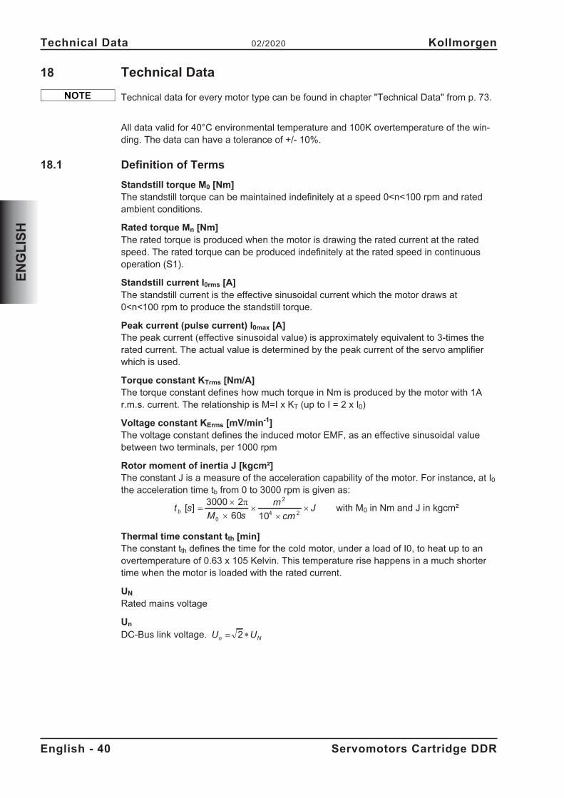
18 Technical Data
Technical data for every motor type can be found in chapter "Technical Data" from p. 73.
All data valid for 40°C environmental temperature and 100K overtemperature of the win-ding. The data can have a tolerance of +/- 10%.
18.1 Definition of Terms
Standstill torque M0 [Nm]The standstill torque can be maintained indefinitely at a speed 0<n<100 rpm and ratedambient conditions.
Rated torque Mn [Nm]The rated torque is produced when the motor is drawing the rated current at the ratedspeed. The rated torque can be produced indefinitely at the rated speed in continuousoperation (S1).
Standstill current I0rms [A]The standstill current is the effective sinusoidal current which the motor draws at0<n<100 rpm to produce the standstill torque.
Peak current (pulse current) I0max [A]The peak current (effective sinusoidal value) is approximately equivalent to 3-times therated current. The actual value is determined by the peak current of the servo amplifierwhich is used.
Torque constant KTrms [Nm/A]The torque constant defines how much torque in Nm is produced by the motor with 1Ar.m.s. current. The relationship is M=I x KT (up to I = 2 x I0)
Voltage constant KErms [mV/min-1]The voltage constant defines the induced motor EMF, as an effective sinusoidal valuebetween two terminals, per 1000 rpm
Rotor moment of inertia J [kgcm²]The constant J is a measure of the acceleration capability of the motor. For instance, at I0the acceleration time tb from 0 to 3000 rpm is given as:
t sM s
m
cmJ
b[ ] �
�
��
��
3000 2
60 100
2
4 2
�with M0 in Nm and J in kgcm²
Thermal time constant tth [min]The constant tth defines the time for the cold motor, under a load of I0, to heat up to anovertemperature of 0.63 x 10⁵ Kelvin. This temperature rise happens in a much shortertime when the motor is loaded with the rated current.
UN
Rated mains voltage
Un
DC-Bus link voltage. U Un N
� �2
English - 40 Servomotors Cartridge DDR
Technical Data 02/2020 Kollmorgen
EN
GL
ISH
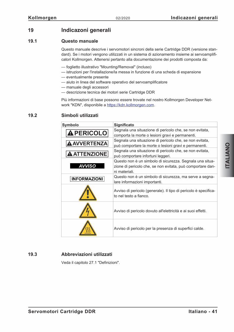
19 Indicazoni generali
19.1 Questo manuale
Questo manuale descrive i servomotori sincroni della serie Cartridge DDR (versione stan-dard). Se i motori vengono utilizzati in un sistema di azionamento insieme ai servoamplifi-catori Kollmorgen. Attenersi pertanto alla documentazione dei prodotti composta da:
— foglietto illustrativo "Mounting/Removal" (incluso)— istruzioni per l'installazione/la messa in funzione di una scheda di espansione— eventualmente presente— aiuto in linea del software operativo del servoamplificatore— manuale degli accessori— descrizione tecnica dei motori serie Cartridge DDR
Più informazioni di base possono essere trovate nel nostro Kollmorgen Developer Net-work "KDN", disponibile a https://kdn.kollmorgen.com.
19.2 Simboli utilizzati
Symbolo SignificatoSegnala una situazione di pericolo che, se non evitata,comporta la morte o lesioni gravi e permanenti.Segnala una situazione di pericolo che, se non evitata,può comportare la morte o lesioni gravi e permanenti.Segnala una situazione di pericolo che, se non evitata,può comportare infortuni leggeri.Questo non è un simbolo di sicurezza. Segnala una situa-zione di pericolo che, se non evitata, può comportare dan-ni materiali.Questo non è un simbolo di sicurezza, ma serve a segna-lare informazioni importanti.
Avviso di pericolo (generale). Il tipo di pericolo è specifica-to nel testo a fianco.
Avviso di pericolo dovuto all'elettricità e ai suoi effetti.
Avviso di pericolo per la presenza di superfici calde.
19.3 Abbreviazioni utilizzati
Veda il capitolo 27.1 "Definizioni".
Servomotori Cartridge DDR Italiano - 41
Kollmorgen 02/2020 Indicazoni generali
ITA
LIA
NO
PERICOLO
20 Sicurezza
20.1 Attenersi a queste indicazioni!
� Il produttore è tenuto a realizzare un'analisi dei rischi per il macchinario e ad adotta-re le misure necessarie, affinché eventuali movimenti imprevisti non causino danni apersone o a cose.
� I lavori di trasporto, montaggio, messa in funzione e manutenzione si possono affi-dare esclusivamente a personale tecnico qualificato, che abbia familiarità con il tra-sporto, l’installazione, il montaggio, la messa in funzione e il funzionamento dei mo-tori e che disponga di opportune qualifiche per lo svolgimento di tali attività:Trasporto: solo a cura di personale con nozioni di movimentazione
componenti sensibili alle cariche elettrostatiche.Installazione mecc.: solo da parte di meccanicai specializzatiInstallazione elett.: solo a cura di elettricisti qualificati.Configurazione: solo a cura di personale qualificato con nozioniapprofondite in materia di elettrotecnica e tecnologia di azionamento.
� Prima di procedere al montaggio e alla messa in funzione leggere la presente docu-mentazione. L'errata manipolazione del motore può comportare danni a persone o acose. Osservare assolutamente i dati tecnici e le indicazioni sulle condizioni di colle-gamento (targhetta di omologazione e documentazione).
� Durante il funzionamento dei motori, il pericolo di morte o gravi per la salute o dannimateriali. L’operatore è quindi tenuto ad assicurarsi che tutto il personale addetto alavori con i motori abbia letto e compreso il manuale e che le indicazioni di sicurezzariportate nel manuale siano rispettate.
� Sollevare e spostare motori con un peso superiore ai 20 kg solo con l'ausilio di op-portuni dispositivi di sollevamento. Sollevare i motori senza dispositivi ausiliari puòcausare lesioni alla schiena.
Alta tensione!
Assicurare la regolare messa a terra della carcassa del motore con la bandella PE all'in-terno dell'armadio di distribuzione come potenziale di riferimento. Pericolo di scossa elet-trica. Senza una messa a terra a bassa impedenza non viene garantita alcuna sicurezzaalle persone.
Non scollegare nessun connettore durante il funzionamento. Rischio di morte o gravilesioni personali in caso di contatto con i contatti liberi. I collegamenti di potenza possonocondurre tensione anche a motore fermo. Non allentare mai i collegamenti elettrici deimotori sotto tensione. In casi sfavorevoli possono venire a crearsi archi voltaici con con-seguenti danni a carico di persone e cose.
Dopo aver scollegato i servoamplificatori dalle tensioni di alimentazione attendere parec-chi minuti prima di toccare i componenti sotto tensione (ad esempio contatti, perni filettati)o di allentare collegamenti. I condensatori nel servoamplificatore conducono tensioni peri-colose parecchi minuti dopo la disinserzione delle tensioni di alimentazione. Per sicu-rezza, misurare la tensione nel circuito intermedio e attendere fino a quando il valore èsceso al di sotto dei 50V.
Superficie calda!
Durante il funzionamento i motori possono presentare super fici calde a seconda del lorogrado di protezione. Pericolo di ustioni!La temperatura superficiale può varcare i 100°C. Misurare la temperatura e attendere cheil motore abbia raggiunto i 40°C prima di toccarlo.
Italiano - 42 Servomotori Cartridge DDR
Sicurezza 02/2020 Kollmorgen
ITA
LIA
NO
20.2 Uso conforme
� I servomotori sincroni della serie Cartridge DDR sono concepiti in particolare comeazionamenti per cilindri di macchine da stampa, macchine tessili, macchine per lalavorazione di pellicole, macchine per imballaggio e similari, con requisiti elevati intermini dinamici.
� Azionare i motori solo nel rispetto delle condizioni stabilite nella presente documen-tazione.
� I motori della serie Cartridge DDR sono esclusivamente destinati ad essere com-andati da servoamplificatori digitali con regolazione della velocità e/o della coppia.
� I motori vengono montati come componenti su impianti o macchine elettrici e posso-no essere messi in funzione solo come componenti integrati dell'impianto.
� Si richiedono l'analisi e il monitoraggio del termocontatto di protezione montato negliavvolgimenti del motore.
� Garantiamo la conformità del servosistema alle norme menzionate nella EC Decla-ration of Conformity (vedi Kollmorgen Website) solo se vengono utilizzati componen-ti originali (servoamplificatori, motore, cavi, e così via).
20.3 Uso conforme vietato
� È vietato l’uso del motor nei seguenti ambienti:- aree a rischio di esplosione- ambienti caratterizzati dalla presenza di acidi, soluzioni alcaline, oli, vapori, polvericorrosivi e/o conduttivi
- direttamente su reti elettriche� L’uso conforme del motore è vietato quando la macchina cui è destinato
- non è conforme alle disposizioni della Direttiva Macchine- non soddisfa le disposizioni della Direttiva sulla Compatibilità Elettromagnetica- non soddisfa le disposizioni della Direttiva Bassa Tensione
Servomotori Cartridge DDR Italiano - 43
Kollmorgen 02/2020 Sicurezza
ITA
LIA
NO
21 Maneggiamento
21.1 Trasporto
Sollevare e spostare motori con un peso superiore ai 20 kgsolo con l'ausilio di opportunidispositivi di sollevamento.� Temperatura di trasporto da -25 a +70°C, variazione max. 20K/ora umidità atmosfe-
rica durante il trasporto:umidità relativa del 5% - 95% senza condensa� Solo da parte di personale qualificato in imballaggio originale riciclabile del produtto-
re� Evitare urti violenti, in particolare sull'estremità dell'albero� In caso di imballaggio danneggiato, verificare che il motore non presenti danni visibi-
li. Informarne il trasportatore ed eventualmente il produttore.
21.2 Imballaggio
� Imballaggio del cartone con rivestimento di Instapak®.� Potete restituire la parte di plastica al fornitore (veda "Smaltimento"
TipoScato-lone
Altezzad’impilaggio max.
Tipo ScatoloneAltezza
d’impilaggio max.C04/CH04 X 10 C09/CH09 X 5C05/CH05 X 10 C13/CH13 X 5C06/CH06 X 5
21.3 Stoccaggio
� Temperatura di stoccaggio da 25 a +55°C, variazione max. 20K/ora� Umidità atmosferica um. rel. del 5% - 95% senza condensa� Solo in imballaggio originale riciclabile del produttore� Per l'altezza d'impilaggio max. ved. tabella imballaggio� Durata a magazzino illimitata
21.4 Manutenzione / Puliza
� Solo da parte di personale qualificato� L'apertura dei motori comporta l'annullamento della garanzia.� Pulizia con isopropanolo o similari, non immergere o nebulizzare
21.5 Riparazioni
Il motori può essere riparato unicamente dal fabbricante; l’apertura dell’apparecchioannulla automaticamente la garanzia. Mettere l’apparecchio fuori servizio e inviarlo alfabbricante.
21.6 Smaltimento
Nell’accordo al WEEE-2012/19/EG guidelines prendiamo i vecchi dispositivi ed accessoriindietro per eliminazione professionale, se i costi del tansport sono y rilevato il mittente.Invia l’apparecchio al fabbricante.
Italiano - 44 Servomotori Cartridge DDR
Maneggiamento 02/2020 Kollmorgen
ITA
LIA
NO
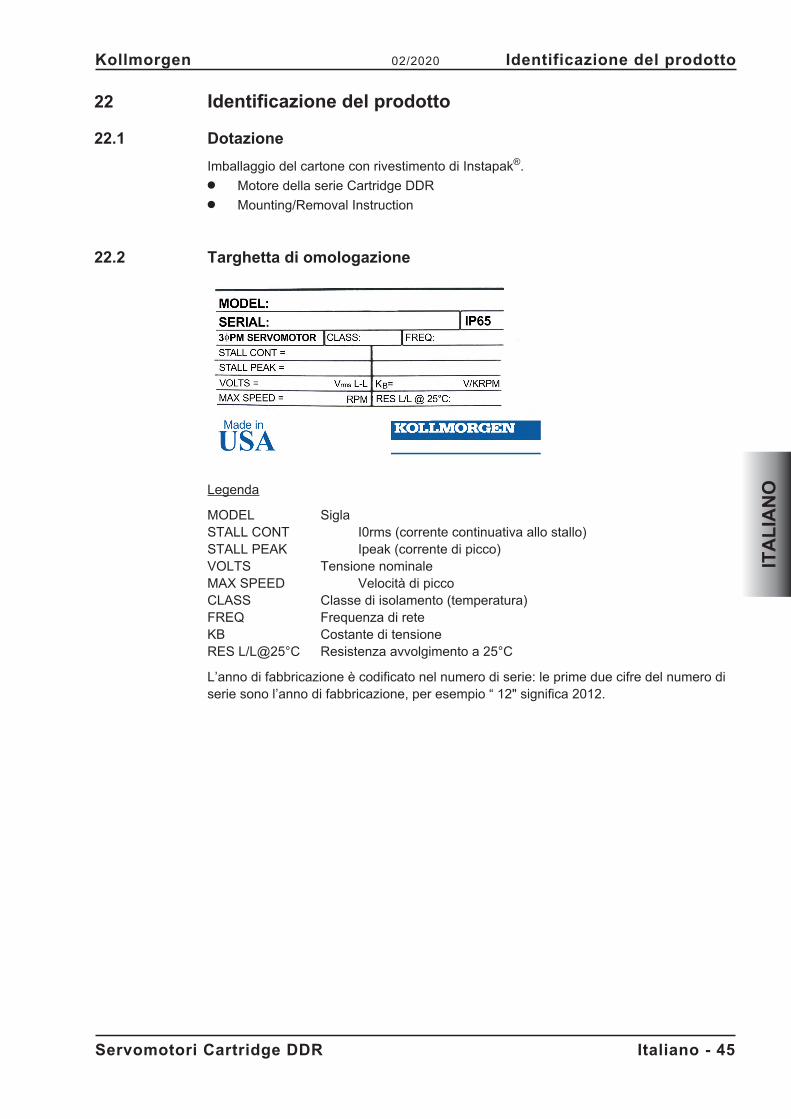
22 Identificazione del prodotto
22.1 Dotazione
Imballaggio del cartone con rivestimento di Instapak®.� Motore della serie Cartridge DDR� Mounting/Removal Instruction
22.2 Targhetta di omologazione
Legenda
MODEL SiglaSTALL CONT I0rms (corrente continuativa allo stallo)STALL PEAK Ipeak (corrente di picco)VOLTS Tensione nominaleMAX SPEED Velocità di piccoCLASS Classe di isolamento (temperatura)FREQ Frequenza di reteKB Costante di tensioneRES L/L@25°C Resistenza avvolgimento a 25°C
L’anno di fabbricazione è codificato nel numero di serie: le prime due cifre del numero diserie sono l’anno di fabbricazione, per esempio “ 12" significa 2012.
Servomotori Cartridge DDR Italiano - 45
Kollmorgen 02/2020 Identificazione del prodotto
ITA
LIA
NO
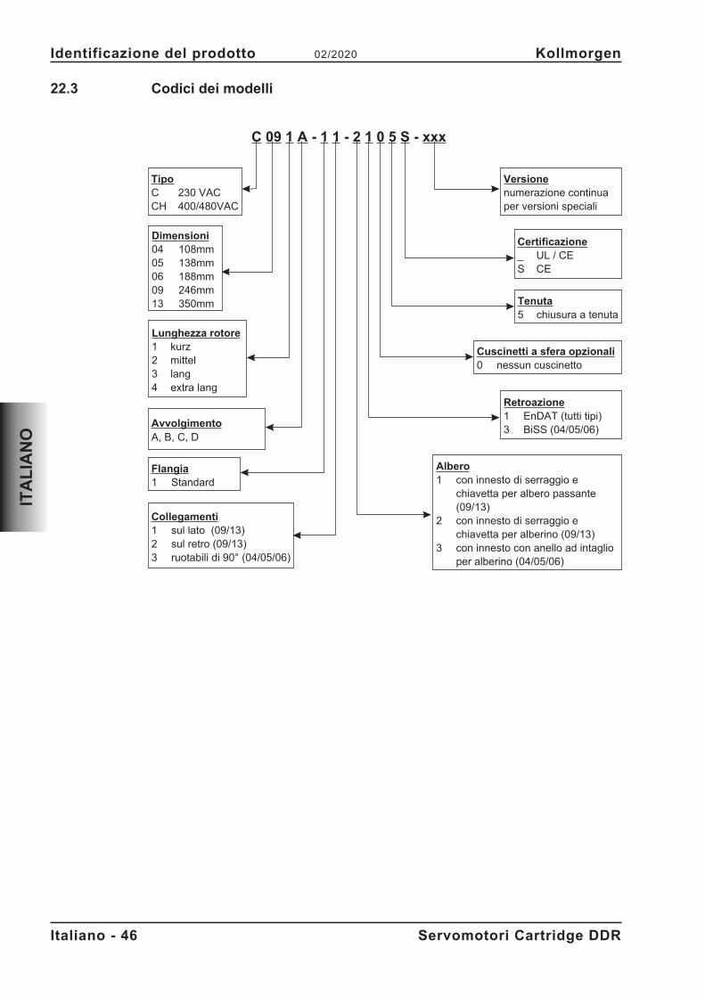
22.3 Codici dei modelli
Italiano - 46 Servomotori Cartridge DDR
Identificazione del prodotto 02/2020 Kollmorgen
ITA
LIA
NO
C 09 1 A - 1 1 - 2 1 0 5 S - xxx
TipoC 230 VACCH 400/480VAC
AvvolgimentoA, B, C, D
Dimensioni04 108mm05 138mm06 188mm09 246mm13 350mm
Lunghezza rotore1 kurz2 mittel3 lang4 extra lang
Cuscinetti a sfera opzionali0 nessun cuscinetto
Tenuta5 chiusura a tenuta
Certificazione_ UL / CES CE
Versionenumerazione continuaper versioni speciali
Flangia1 Standard
Collegamenti1 sul lato (09/13)2 sul retro (09/13)3 ruotabili di 90° (04/05/06)
Retroazione1 EnDAT (tutti tipi)3 BiSS (04/05/06)
Albero1 con innesto di serraggio e
chiavetta per albero passante(09/13)
2 con innesto di serraggio echiavetta per alberino (09/13)
3 con innesto con anello ad intaglioper alberino (04/05/06)
23 Descrizione tecnizi
23.1 Dati tecnici generali
Temperatura ambiente da 5 a +40°C ad un'altitudine d'installazione fino a(ai dati nominali) 1000 m sopra il livello del mare
In caso di temperature ambiente superiori ai 40°C e dimotori in esecuzione chiusa contattare il nostro settoreapplicazioni.
Umidità atmosferica ammessa Umidità relativa dell'95%, non soggetta a condensa(ai dati nominali)Riduzione delle prestazioni 1%/K in un intervallo da 40°C a 50°C fino a 1000m(correnti e coppie) sopra il livello del mare (LdM)
Per altitudini oltre i 1000 m sopra il LdM e e 40°C6% a 2000 m sopra il LdM17% a 3000 m sopra il LdM30% a 4000 m sopra il LdM55% a 5000 m sopra il LdM
Nessuna riduzione delle prestazioni ad altitudinioltre i 1000 m sopra il LdM e riduzione della temp. di10K/1000m
Per i dati tecnici di ogni tipo di motore consultare il capitolo "Technical Data" da p. 73.
23.1.1 Forma costructtiva
Il montaggio del motore può avvenire in qualsiasi posizione, quindi anche su alberi oriz-zontali o verticali.
23.1.2 Flangia
I motori Cartridge DDR non dispongono di flangia propria, vengono invece montati sullaflangia della macchina con un innesto di serraggio e un anello di centraggio. Per il cen-traggio sulla flangia della macchina viene impiegato un anello adattatore posto sulmotore, mentre l’innesto di serraggio fissa il rotore integrato sull’albero della macchina. Ilmotore non è provvisto di cuscinetto proprio.
Per i requisiti relativi alla flangia consultare i capitoli 24.2 e 24.3.
Per i motori C(H) 09 e C(H) 13 è disponibile una versione con apertura per alberi cavipassanti.
Servomotori Cartridge DDR Italiano - 47
Kollmorgen 02/2020 Descrizione tecnizi
ITA
LIA
NO
23.1.3 Grado di protezione
Versione per alberini (2, 3): IP65 per flangia macchina con chiusura a tenutaVersione con albero cavo (1): IP64 per flangia macchina con chiusura a tenuta
23.1.4 Classe di isolamento
I motori sono conformi alla classe isolante F secondo IEC 60085 (UL 1446 class F).
23.1.5 Superficie
I motori sono ricoperti di rivestimento della polvere del poliestere nel nero opaco nonresistente ai solventi (tricloroetilene, diluenti o altro).
23.1.6 Dispositivo di protezione
Nella versione standard ogni motore dispone di un PTC a potenziale zero. Il punto dicommutazione è a 155°C ± 5%. Questo PTC non offre alcuna protezione nei confronti disovraccarichi brevi molto elevati. Utilizzando il nostro cavo per Encoder preconfezionato ilPTC è integrato nel sistema di controllo dei servoamplificatori digitali.
23.1.7 Sistema di collegamento
I motori sono dotati di connettori diritti per l’alimentazione di potenza e i segnalidell’encoder. A seconda della versione, i connettori sono orientati sul lato o sul retro delmotore oppure sono ruotabili di 90°.
Le prese femmina non fanno parte della dotazione. I cavi di retroazione e di potenzasono disponibili già confezionati.
23.1.8 Unità di retroazione
C(H) yyxx-xx-x1xxEncoder sin/cos ad alta risoluzione, Singleturn, ECN1313 (2048 periodo), EnDat
C(H) 04xx-xx-x3xx, C(H) 05xx-xx-x3xx und C(H) 06xx-xx-x3xxEncoder sin/cos ad alta risoluzione, Singleturn, Hengstler ACURO AD36 (2048 periodo);BiSS
Italiano - 48 Servomotori Cartridge DDR
Descrizione tecnizi 02/2020 Kollmorgen
ITA
LIA
NO
24 Installazione meccanica
Le illustrazioni di dimensione possono essere trovate nel capitolo"Dimension Drawings"p.79.
24.1 Indicazioni importanti
Solo personale tecnico con esperienza di montaggio meccanico può montare il motore.
Montare e cablare i motori sempre in assenza di tensione, vale a dire senzainserire la tensione d’esercizio degli apparecchi da collegare. In caso di contattocon contatti liberi sussiste rischio di morte o di gravi lesioni personali.
Assicurarsi che il quadro elettrico venga disinserito in modo sicuro (blocco,cartelli di avvertenza, e così via). Le singole tensioni verranno inserite solo conla messa in funzione.
Si tratta di una parte magnetica che attira il ferro. Coprire l’estremità del motore per evita-re che si sporchi.
� Proteggere i motori da sollecitazioni non ammesse.In particolare, durante il trasporto e la movimentazione non piegare elementi costrut-tivi e/o modificare le distanze d'isolamento.
� Il luogo di installazione deve essere privo di materiali conduttivi e aggressivi. In casodi montaggio in esecuzione chiusa consultare prima il nostro settore applicazioni.
� Montare il motore seguendo le indicazioni a partire da pagina 50.Accertarsi che il montaggio del motore non venga forzato a livello meccanico.
� Assicurare la libera ventilazione dei motori e rispettare i valori ammessi per la tem-peratura ambiente e della flangia. In caso di temperature ambiente superiori ai 40°Cconsultare prima il nostro settore applicazioni.
Servomotori Cartridge DDR Italiano - 49
Kollmorgen 02/2020 Installazione meccanica
ITA
LIA
NO
PERICOLO
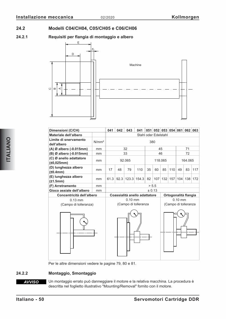
24.2 Modelli C04/CH04, C05/CH05 e C06/CH06
24.2.1 Requisiti per flangia di montaggio e albero
Dimensioni (C/CH) 041 042 043 041 051 052 053 054 061 062 063
Materiale dell’albero Stahl oder EdelstahlLimite di snervamentodell’albero
N/mm² 380
(A) Ø albero (-0.015mm) mm 32 45 71(B) Ø albero (-0.015mm) mm 33 46 72(C) Ø anello adattatore(±0,025mm)
mm 92.065 118.065 164.065
(D) lunghezza albero(±0.4mm)
mm 17 48 79 110 35 60 85 110 49 83 117
(E) lunghezza albero(±1.5mm)
mm 61.3 92.3 123.3 154.3 82 107 132 157 104 138 172
(F) Arretramento mm > 5.5Gioco assiale dell’albero mm ± 0.13
Concentricità dell’albero Coassialità anello adattatore Ortogonalità flangia
0.13 mm(Campo di tolleranza)
0.10 mm(Campo di tolleranza
0.10 mm(Campo di tolleranza
Per le altre dimensioni vedere le pagine 79, 80 e 81.
24.2.2 Montaggio, Smontaggio
Un montaggio errato può danneggiare il motore e la relativa macchina. La procedura èdescritta nel foglietto illustrativo "Mounting/Removal" fornito con il motore.
Italiano - 50 Servomotori Cartridge DDR
Installazione meccanica 02/2020 Kollmorgen
ITA
LIA
NO
BC
E
A
F
D
Machine
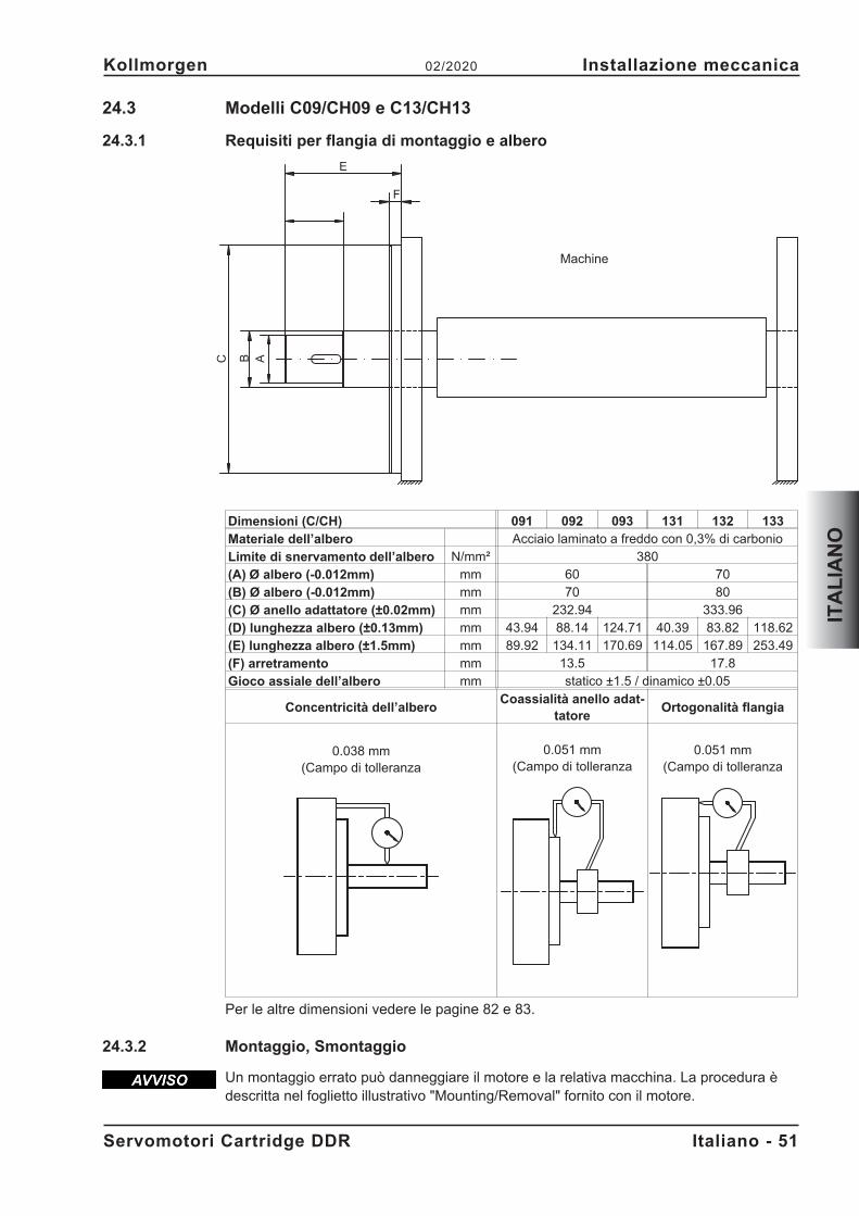
24.3 Modelli C09/CH09 e C13/CH13
24.3.1 Requisiti per flangia di montaggio e albero
Dimensioni (C/CH) 091 092 093 131 132 133
Materiale dell’albero Acciaio laminato a freddo con 0,3% di carbonioLimite di snervamento dell’albero N/mm² 380(A) Ø albero (-0.012mm) mm 60 70(B) Ø albero (-0.012mm) mm 70 80(C) Ø anello adattatore (±0.02mm) mm 232.94 333.96(D) lunghezza albero (±0.13mm) mm 43.94 88.14 124.71 40.39 83.82 118.62(E) lunghezza albero (±1.5mm) mm 89.92 134.11 170.69 114.05 167.89 253.49(F) arretramento mm 13.5 17.8Gioco assiale dell’albero mm statico ±1.5 / dinamico ±0.05
Concentricità dell’alberoCoassialità anello adat-
tatoreOrtogonalità flangia
0.038 mm(Campo di tolleranza
0.051 mm(Campo di tolleranza
0.051 mm(Campo di tolleranza
Per le altre dimensioni vedere le pagine 82 e 83.
24.3.2 Montaggio, Smontaggio
Un montaggio errato può danneggiare il motore e la relativa macchina. La procedura èdescritta nel foglietto illustrativo "Mounting/Removal" fornito con il motore.
Servomotori Cartridge DDR Italiano - 51
Kollmorgen 02/2020 Installazione meccanica
ITA
LIA
NO
BC
E
A
F
Machine
25 Installazione elettrica
Gli schemi elettrici possono essere trovati nel capitolo "Wiring Diagrams" p.79.
25.1 Indicazioni importanti
Solo personale tecnico con esperienza nei collegamenti elettrici può cablare il motore.
Montare e cablare i motori sempre in assenza di tensione, vale a dire senzainserire la tensione d’esercizio degli apparecchi da collegare. In caso di contattocon contatti liberi sussiste rischio di morte o di gravi lesioni personali.
Assicurarsi che il quadro elettrico venga disinserito in modo sicuro (blocco,cartelli di avvertenza, e così via). Le singole tensioni verranno inserite solo conla messa in funzione.
Non allentare mai i collegamenti elettrici dei motori sotto tensione. Pericolo discossa elettrica! In casi sfavorevoli possono venire a crearsi archi voltaici conconseguenti danni a carico di persone e contatti.
I condensatori del servoamplificatore possono presentare cariche residuepericolose fino a 10 minuti dopo l’interruzione della tensione di rete. Icollegamenti di comando e di potenza possono condurre tensione anche amotore fermo.
Misurare la tensione nel circuito intermedio e attendere fino a quando il valore èsceso al di sotto dei 50V.
Il simbolo messa a terra� che si trova in tutti gli schemi di collegamento indica cheoccorre provvedere ad un collegamento conduttivo il più ampio possibile tra l'apparecchioidentificato e la piastra di montaggio nel quadro elettrico ad armadio. Tale collegamentodeve consentire la dispersione di interferenze ad alta frequenza e non deve essere con-fuso con il simbolo di terra PE (misura di protezione secondo EN 60204). Osservare an-che le note negli schemi di collegamento delle manuale di istruzioni del servoamplificato-re utilizzato.
25.2 Collegamento dei motori
� Eseguire il cablaggio in base alle disposizioni ed alle norme vigenti.� Per il collegamento di potenza e di retroazione utilizzare esclusivamente cavi scher-
mati preconfezionati di Kollmorgen.� Schermature non posizionate correttamente possono portare a interferenze EMV e
possono pregiudicare il funzionamento del sistema.� Lunghezza dei cavi max.: attenersi manuali d'istruzzione del servoamplificatore.
Per la descrizione dettagliata dei cavie confezionamento consultare il manuale degliaccessori.
Italiano - 52 Servomotori Cartridge DDR
Installazione elettrica 02/2020 Kollmorgen
ITA
LIA
NO
PERICOLO
25.3 Guida ad installazione elettrica
� Verificare l'abbinamento tra servoamplificatori e motore. Confrontare la tensione no-minale e la corrente nominale degli apparecchi. Eseguire il cablaggio in base alloschema di collegamento riportato sul manuale del servoamplificatore. I collegamentidel motore sono indicati da capitolo "Wiring Diagrams" p.79.
� Tutti i cavi che conducono correnti elevate devono avere sezione sufficiente secon-do EN 60204. Le sezioni consigliate sono indicate nei dati tecnici.
� Nel caso del motore lungo cavo (>25m) ed il dipendente sul tipo del servoamplifica-tore utilizzato una scatola induttore (3YL / 3YLN) deve essere commutato nel cavodel motore (veda il manuale di istruzioni del servoamplificatore ed il manuale acces-sorio).
� Assicurarsi che la messa a terra di servoamplificatore e motore venga eseguita a re-gola d'arte. Per una schermatura e una messa a terra conformi ai requisiti di compa-tibilità elettromagnetica si vedano le manuale del servoamplificatore utilizzato. Colle-gare a terra la piastra di montaggio e la carcassa del motore.
� Cablaggio— Se possibile, posare separatamente i cavi di potenza e di comando— Collegare l'unità di retroazione— Collegare i cavi del motore, l'induttore per motore vicino al Servoamplificatore— le schermature, su entrambe le estremità, ai morsetti o ai connettori EMC— Posare la schermatura su entrambi i lati
� Collegare le schermature in modo da coprire un'ampia superficie (a bassa impeden-za), mediante un corpo connettore metallizzato o connettori filettati per cavi conformiai requisiti sulla compatibilità elettromagnetica.
� Requisiti a materiale dei cavi:CapacitàCavo di motore - inferiore a 150 pF/mCavo die retroazione - inferiore a 120 pF/m
Servomotori Cartridge DDR Italiano - 53
Kollmorgen 02/2020 Installazione elettrica
ITA
LIA
NO
26 Messa in funzione
26.1 Indicazioni importanti
Solo tecnici con ampie conoscenze di elettrotecnica/tecniche di movimentazione possonomettere in funzione l'unità di azionamento con servoamplificatore/motore.
Presenza di tensioni letali fino a 900V. Pericolo di scossa elettrica! Verificareche tutti gli elementi di collegamento sotto tensione siano protetti in modo sicurocontro il contatto.
Non allentare mai i collegamenti elettrici dei motori sotto tensione. Icondensatori del servoamplificatore possono presentare cariche residuepericolose fino a 10 minuti dopo l’interruzione della tensione di rete. Misurare latensione nel circuito intermedio e attendere fino a quando il valore è sceso al disotto dei 50V. I collegamenti di comando e di potenza possono condurretensione anche a motore fermo.
La temperatura superficiale del motore può varcare i 100°C durante ilfunzionamento. Pericolo di ustioni lievi! Verificare (misurare) la temperatura delmotore.Prima di toccarlo attendere che abbia raggiunto i 40°C.
Durante la messa in funzione non è possibile escludere un movimentoimprevisto dell’azionamento. Assicurarsi che qualsiasi movimento accidentaledell’azionamento non possa causare pericolo per persone o cose. Le misurenecessarie in questo caso per un’applicazione specifica possono esseredesunte dall’analisi dei rischi dell’applicazione.
26.2 Guida ad messa in funzione
A titolo di esempio descriviamo la procedura da seguire per la messa in funzione.A seconda dell'impiego previsto può risultare opportuna o necessaria una proceduradiversa.� Controllare il montaggio e l'orientamento del motore.� Controllare il cablaggio e i collegamenti su motore e servoamplificatore. Assicurarsi
che la messa a terra venga effettuata a regola d'arte.� Verificare se il rotore del motore può ruotare liberamente. Prestare attenzione ai ru-
mori di sfregamento.� Verificare che siano state adottate tutte le misure di protezione dal contatto neces-
sarie per i componenti mobili e sotto tensione.� Eseguire gli ulteriori controlli specifici e necessari per l'impianto in uso.� Mettere in funzione l'azionamento in base alle istruzioni per la messa in funzione del
servoamplificatore.� In caso di sistemi multiasse mettere in funzione ogni unità di azionamento del servo-
amplificatore/motore singolarmente.
Italiano - 54 Servomotori Cartridge DDR
Messa in funzione 02/2020 Kollmorgen
ITA
LIA
NO
PERICOLO
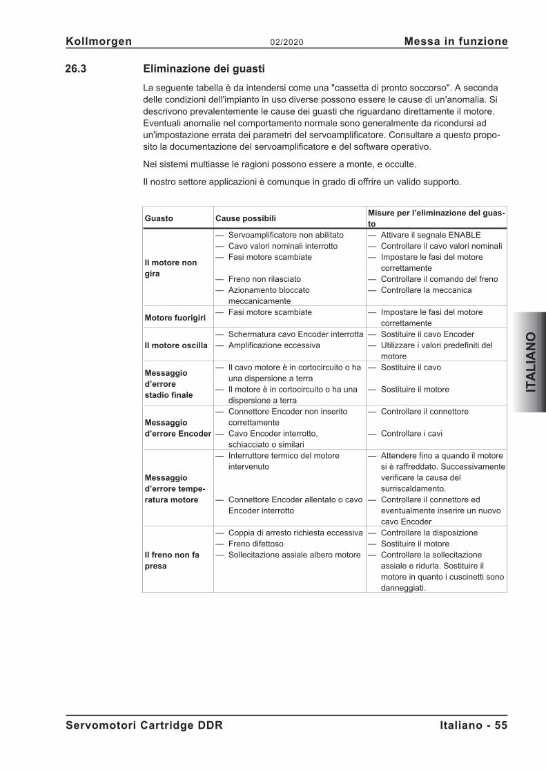
26.3 Eliminazione dei guasti
La seguente tabella è da intendersi come una "cassetta di pronto soccorso". A secondadelle condizioni dell'impianto in uso diverse possono essere le cause di un'anomalia. Sidescrivono prevalentemente le cause dei guasti che riguardano direttamente il motore.Eventuali anomalie nel comportamento normale sono generalmente da ricondursi adun'impostazione errata dei parametri del servoamplificatore. Consultare a questo propo-sito la documentazione del servoamplificatore e del software operativo.
Nei sistemi multiasse le ragioni possono essere a monte, e occulte.
Il nostro settore applicazioni è comunque in grado di offrire un valido supporto.
Guasto Cause possibiliMisure per l’eliminazione del guas-to
Il motore nongira
— Servoamplificatore non abilitato— Cavo valori nominali interrotto— Fasi motore scambiate
— Freno non rilasciato— Azionamento bloccato
meccanicamente
— Attivare il segnale ENABLE— Controllare il cavo valori nominali— Impostare le fasi del motore
correttamente— Controllare il comando del freno— Controllare la meccanica
Motore fuorigiri— Fasi motore scambiate — Impostare le fasi del motore
correttamente
Il motore oscilla— Schermatura cavo Encoder interrotta— Amplificazione eccessiva
— Sostituire il cavo Encoder— Utilizzare i valori predefiniti del
motore
Messaggiod’errorestadio finale
— Il cavo motore è in cortocircuito o hauna dispersione a terra
— Il motore è in cortocircuito o ha unadispersione a terra
— Sostituire il cavo
— Sostituire il motore
Messaggiod’errore Encoder
— Connettore Encoder non inseritocorrettamente
— Cavo Encoder interrotto,schiacciato o similari
— Controllare il connettore
— Controllare i cavi
Messaggiod’errore tempe-ratura motore
— Interruttore termico del motoreintervenuto
— Connettore Encoder allentato o cavoEncoder interrotto
— Attendere fino a quando il motoresi è raffreddato. Successivamenteverificare la causa delsurriscaldamento.
— Controllare il connettore edeventualmente inserire un nuovocavo Encoder
Il freno non fapresa
— Coppia di arresto richiesta eccessiva— Freno difettoso— Sollecitazione assiale albero motore
— Controllare la disposizione— Sostituire il motore— Controllare la sollecitazione
assiale e ridurla. Sostituire ilmotore in quanto i cuscinetti sonodanneggiati.
Servomotori Cartridge DDR Italiano - 55
Kollmorgen 02/2020 Messa in funzione
ITA
LIA
NO
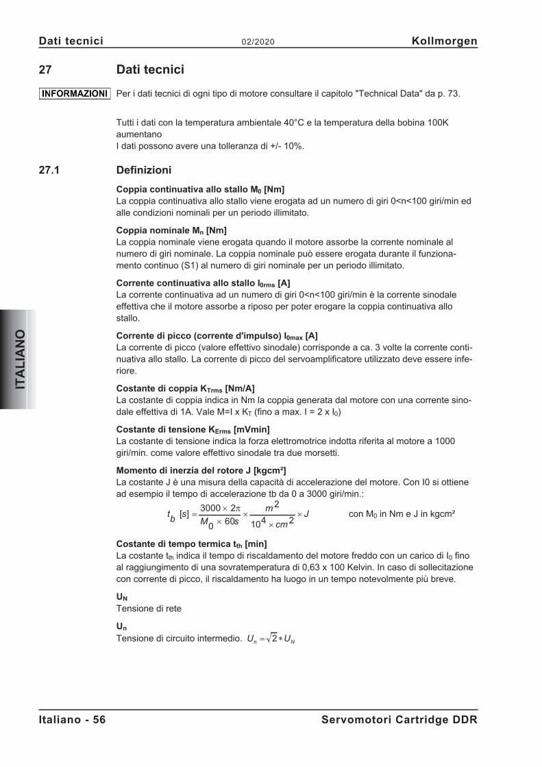
27 Dati tecnici
Per i dati tecnici di ogni tipo di motore consultare il capitolo "Technical Data" da p. 73.
Tutti i dati con la temperatura ambientale 40°C e la temperatura della bobina 100KaumentanoI dati possono avere una tolleranza di +/- 10%.
27.1 Definizioni
Coppia continuativa allo stallo M0 [Nm]La coppia continuativa allo stallo viene erogata ad un numero di giri 0<n<100 giri/min edalle condizioni nominali per un periodo illimitato.
Coppia nominale Mn [Nm]La coppia nominale viene erogata quando il motore assorbe la corrente nominale alnumero di giri nominale. La coppia nominale può essere erogata durante il funziona-mento continuo (S1) al numero di giri nominale per un periodo illimitato.
Corrente continuativa allo stallo I0rms [A]La corrente continuativa ad un numero di giri 0<n<100 giri/min è la corrente sinodaleeffettiva che il motore assorbe a riposo per poter erogare la coppia continuativa allostallo.
Corrente di picco (corrente d'impulso) I0max [A]La corrente di picco (valore effettivo sinodale) corrisponde a ca. 3 volte la corrente conti-nuativa allo stallo. La corrente di picco del servoamplificatore utilizzato deve essere infe-riore.
Costante di coppia KTrms [Nm/A]La costante di coppia indica in Nm la coppia generata dal motore con una corrente sino-dale effettiva di 1A. Vale M=I x KT (fino a max. I = 2 x I0)
Costante di tensione KErms [mVmin]La costante di tensione indica la forza elettromotrice indotta riferita al motore a 1000giri/min. come valore effettivo sinodale tra due morsetti.
Momento di inerzia del rotore J [kgcm²]La costante J è una misura della capacità di accelerazione del motore. Con I0 si ottienead esempio il tempo di accelerazione tb da 0 a 3000 giri/min.:
tb
sM s
m
cm
J[ ] ��
��
�
�3000 2
0 60
2
104 2�
con M0 in Nm e J in kgcm²
Costante di tempo termica tth [min]La costante tth indica il tempo di riscaldamento del motore freddo con un carico di I0 finoal raggiungimento di una sovratemperatura di 0,63 x 100 Kelvin. In caso di sollecitazionecon corrente di picco, il riscaldamento ha luogo in un tempo notevolmente più breve.
UN
Tensione di rete
Un
Tensione di circuito intermedio. U Un N
� �2
Italiano - 56 Servomotori Cartridge DDR
Dati tecnici 02/2020 Kollmorgen
ITA
LIA
NO
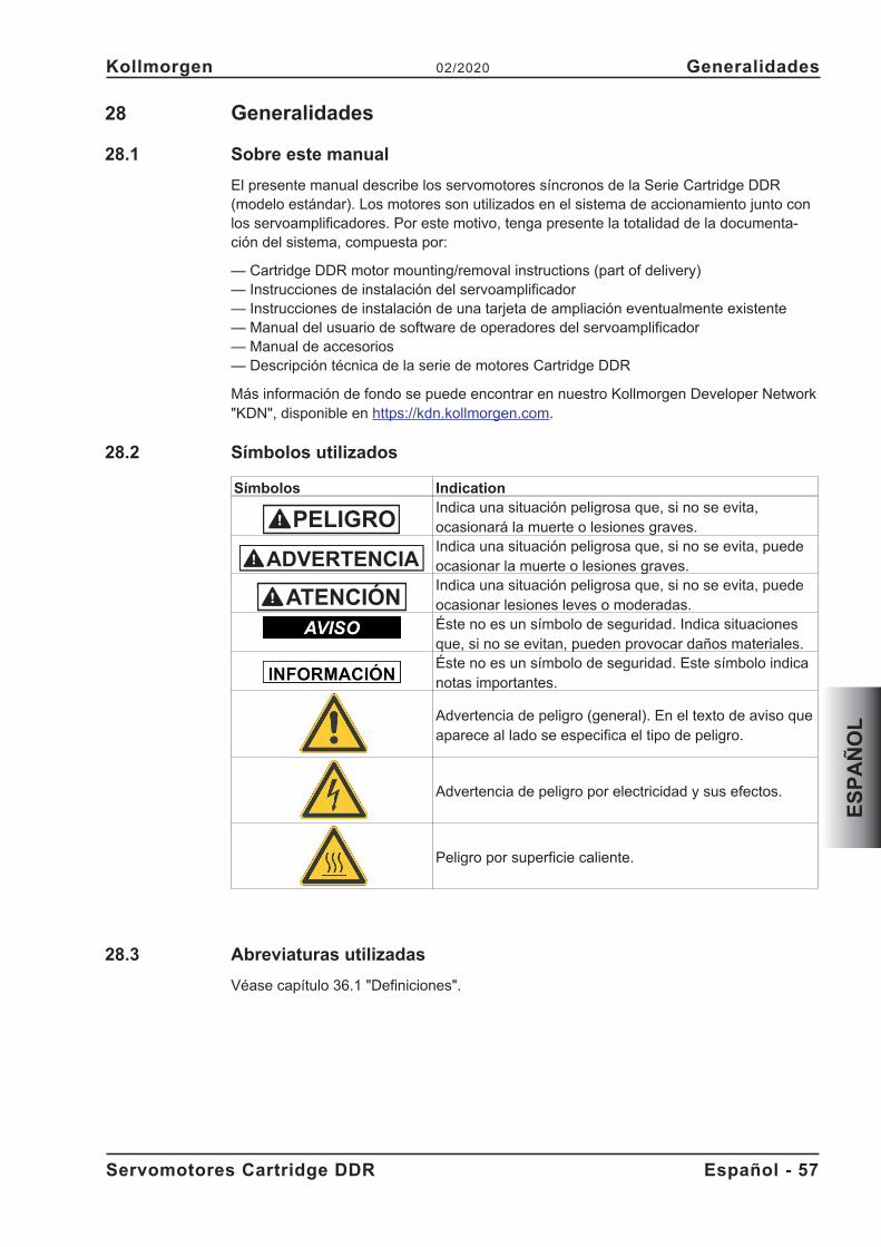
28 Generalidades
28.1 Sobre este manual
El presente manual describe los servomotores síncronos de la Serie Cartridge DDR(modelo estándar). Los motores son utilizados en el sistema de accionamiento junto conlos servoamplificadores. Por este motivo, tenga presente la totalidad de la documenta-ción del sistema, compuesta por:
— Cartridge DDR motor mounting/removal instructions (part of delivery)— Instrucciones de instalación del servoamplificador— Instrucciones de instalación de una tarjeta de ampliación eventualmente existente— Manual del usuario de software de operadores del servoamplificador— Manual de accesorios— Descripción técnica de la serie de motores Cartridge DDR
Más información de fondo se puede encontrar en nuestro Kollmorgen Developer Network"KDN", disponible en https://kdn.kollmorgen.com.
28.2 Símbolos utilizados
Símbolos IndicationIndica una situación peligrosa que, si no se evita,ocasionará la muerte o lesiones graves.Indica una situación peligrosa que, si no se evita, puedeocasionar la muerte o lesiones graves.Indica una situación peligrosa que, si no se evita, puedeocasionar lesiones leves o moderadas.Éste no es un símbolo de seguridad. Indica situacionesque, si no se evitan, pueden provocar daños materiales.Éste no es un símbolo de seguridad. Este símbolo indicanotas importantes.
Advertencia de peligro (general). En el texto de aviso queaparece al lado se especifica el tipo de peligro.
Advertencia de peligro por electricidad y sus efectos.
Peligro por superficie caliente.
28.3 Abreviaturas utilizadas
Véase capítulo 36.1 "Definiciones".
Servomotores Cartridge DDR Español - 57
Kollmorgen 02/2020 Generalidades
ES
PA
ÑO
L
PELIGRO
ADVERTENCIA
29 Seguridad
29.1 Siga sus instrucciones!
� El fabricante de la máquina elaborarár un análisis de riesgo de la máquina yadoptará las medidas adecuadas para que movimientos imprevistos no puedancausar daños personales ni materiales.
� Las operaciones de transporte, instalación, puesta en funcionamiento y manten-imiento sólo podrán ser realizadas por personal cualificado. Por personal cualificadose entiende las personas que están familiarizadas con el transporte, la instalación,el montaje, la puesta en funcionamiento y el manejo del producto y que disponen delas correspondientes calificaciones profesionales.Transporte: sólo a cargo de personal con conocimientos de ma-nejo de elementos de montaje con riesgo electrostáticoInstalación mecánica: sólo a cargo de personal especializado con forma-ción en ingeniería mecánicaInstalación eléctrica: sólo a cargo de personal especializado con forma-ción en electrotecniaPuesta en funcionamiento:sólo a cargo de personal especializado con ampliosconocimientos sobre electrotecnia y la técnica de accionamientos
� Antes del montaje y de la puesta en funcionamiento, lea detenidamente la presentedocumentación. La incorrecta manipulación del motor puede producir daños perso-nales y materiales. La observación de los datos técnicos y las indicaciones de con-exión (placa de identificación y documentación) son de obligado cumplimiento.
� Durante la operación de los motores, el peligro de muerte o grave o daños materia-les. Por este motivo, el operador debe asegurarse de que todas las personas quevayan a realizar trabajos en el motor hayan leído y comprendido el manual, y deque se cumplan las instrucciones de seguridad que contiene.
� Para elevar y desplazar motores con un peso superior a 20 kg, utilice siempre dis-positivos elevadores. Si se elevan estas piezas sin la ayuda de herramientas, pue-den producirse lesiones en la espalda.
¡Altas tensiones!
Asegúrese de la adecuada puesta a tierra del bloque del motor con la barra colectora delarmario de distribución como potencial de referencia. Riesgo de descarga eléctrica.Careciendo de una toma de tierra de baja resistencia no se puede garantizar la seguri-dad personal.
No extraiga ningún enchufe con el equipo en marcha. Existe el peligro de muerte o lesio-nes graves al tocar los contactos expuestos. Las conexiones pueden llevar tensión,incluso con el motor parado. No suelte nunca las conexiones eléctricas estando bajo ten-sión. En circunstancias desfavorables se pueden producir chispazos que dañen a laspersonas y a los contactos.
Al desconectar el servoamplificador de la corriente de alimentación, espere varios minu-tos antes de soltar piezas conductoras de corriente (por ejemplo, contactos, etc.). Loscondensadores en el servoamplificador conducen tensiones peligrosas hasta unos variosminutos después de cortar la alimentación de corriente. Para mayor seguridad, mida lacorriente en el circuito intermedio y espere a que la corriente se sitúe por debajo de 50V.
¡Superficie caliente!
Durante el funcionamiento, los motores pueden tener superficies calientes según la clasede protección. Riesgo de quemaduras! La temperatura de las superficies puede alcanzar100°C. Mida la temperatura y, antes de tocar el motor, espere hasta que se hayaenfriado a 40°C.
Español - 58 Servomotores Cartridge DDR
Seguridad 02/2020 Kollmorgen
ES
PA
ÑO
L
29.2 Utilización conforme
� Los servomotores síncronos de la serie Cartridge DDR están concebidos especial-mente como accionamientos de rodillos para máquinas de artes gráficas, textiles,laminadoras, envasadoras y embaladoras y similares que tengan requisitos dedinámica elevados.
� Están solamente autorizados a operar en motores cumpliendo las condiciones delentorno definidas en la presente documentación.
� Los motores de la Serie Cartridge DDR está exclusivamente destinados a ser acti-vados mediante servoamplificadores digitales regulados por velocidad y/o por parmotor.
� Los motores se montan como componentes de instalaciones eléctricas o maquina-ria y solamente pueden ser puestos en servicio como componentes integrados.
� El contacto de termoprotección incorporado en el arrollamiento del motor será eva-luado y comprobado.
� Garantizamos la conformidad del servosistema con los términos de la EC Declarati-on of Conformity (véase Kollmorgen Website), solamente cuando se utilicen loscomponentes entregados por nosotros (servoamplificador, motor, cables, etc.).
29.3 Uso indebido
� Está prohibido utilizar los motores en los siguientes entornos:- Zonas con riesgo de explosión- entornos con polvos, vapores, aceites, lejías y ácidos corrosivos o conductoresde electricidad
- Funcionamiento directo en la red� Está prohibido utilizar el motor si la máquina en la que está instalado:
- no cumple las disposiciones de la directiva comunitaria sobre máquinas;- no cumple las disposiciones de la directiva sobre compatibilidad electromagnética;- no cumple las disposiciones de la directiva sobre equipos de baja tensión.
Servomotores Cartridge DDR Español - 59
Kollmorgen 02/2020 Seguridad
ES
PA
ÑO
L
30 Manipulación
30.1 Transporte
Para elevar y desplazar motores con un peso superior a 20 kg, utilice siempre dispositi-vos elevadores.� Temperatura -25...+70° C, oscilación máx. 20K / hora
Humedad del aire humedad relativa máx. 5%... 95% sin condensar� Sólo a cargo de personal especializado en el envase original reciclable del fabrican-
te� Evite impactos fuertes, particularmente sobre el extremo del eje� En caso de que el embalaje esté dañado, compruebe que el aparato no tiene
daños visibles. Informe de ello al transportista y, en caso necesario, al fabricante.
30.2 Embalaje
� Caja de cartón amortiguador de la espuma de Instapak®.� Usted puede volver la porción plástica al surtidor (véase la “Eliminación”).
ModeloCaja decartón
Altura máx. de estiba ModeloCaja decartón
Altura máx. deestiba
C04/CH04 X 10 C09/CH09 X 5C05/CH05 X 10 C13/CH13 X 5C06/CH06 X 5
30.3 Almacenamiento
� Temp. de almacenamiento -25...+55°C, oscilación máx. 20K/hora� Humedad del aire humedad rel. máx. 5% ... 95% sin condensar� Sólo en el embalaje original reciclable del fabricante� Altura máx. de apilamiento véase en la tabla de embalaje� Tiempo de almacenamiento sin limitación
30.4 Advertenzia / Limpieza
� Advertenzia / limpieza sólo por personal profesional� La apertura de los motores trae consigo la pérdida de la garantía� Límpiese con isopropanol o producto similar no sumergir ni pulverizar
30.5 Reparación
Sólo el fabricante debe ejecutar reparaciones en el motor; la apertura de los aparatosinvalida la garantía. Ponga el aparato fuera de servicio y envíelo al fabricante.
30.6 Eliminación
De conformidad con la directiva 2012/19/CE (RAEE), nos encargamos de eliminar demanera adecuada los aparatos y accesorios viejos si el remitente se hace cargo de losgastos de transporte. Envíe el dispositivo al fabricante.
Español - 60 Servomotores Cartridge DDR
Manipulación 02/2020 Kollmorgen
ES
PA
ÑO
L
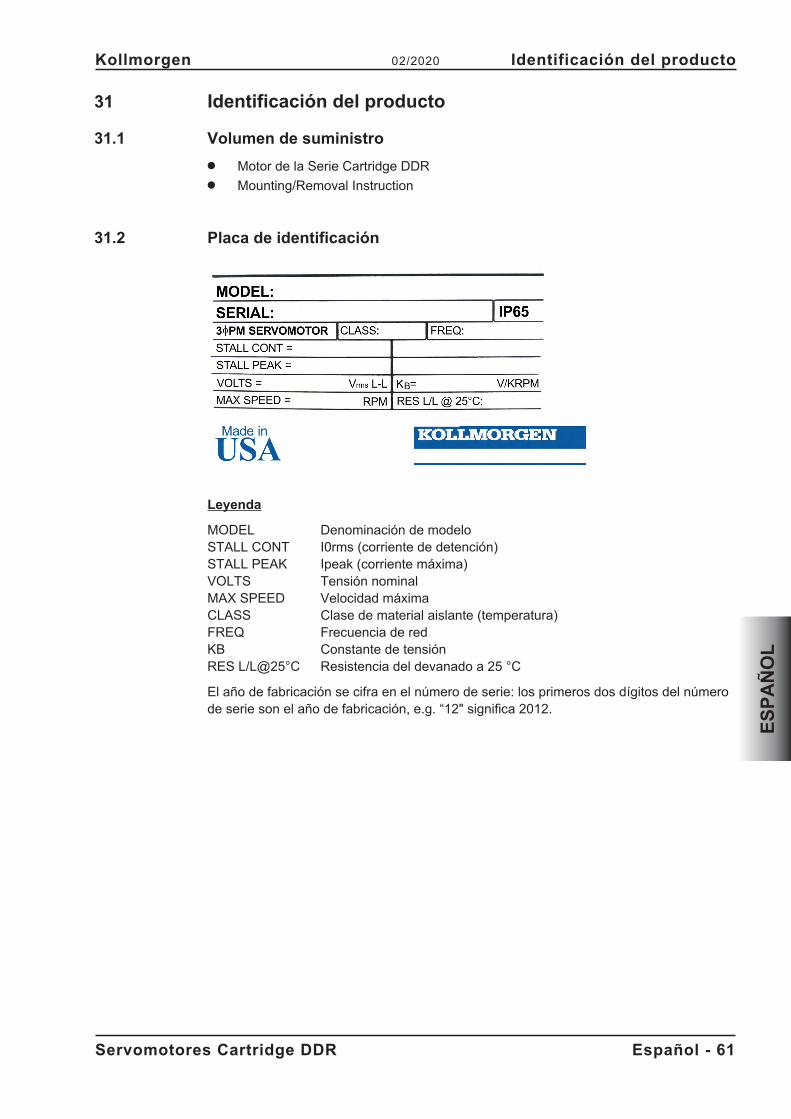
31 Identificación del producto
31.1 Volumen de suministro
� Motor de la Serie Cartridge DDR� Mounting/Removal Instruction
31.2 Placa de identificación
Leyenda
MODEL Denominación de modeloSTALL CONT I0rms (corriente de detención)STALL PEAK Ipeak (corriente máxima)VOLTS Tensión nominalMAX SPEED Velocidad máximaCLASS Clase de material aislante (temperatura)FREQ Frecuencia de redKB Constante de tensiónRES L/L@25°C Resistencia del devanado a 25 °C
El año de fabricación se cifra en el número de serie: los primeros dos dígitos del númerode serie son el año de fabricación, e.g. “12" significa 2012.
Servomotores Cartridge DDR Español - 61
Kollmorgen 02/2020 Identificación del producto
ES
PA
ÑO
L
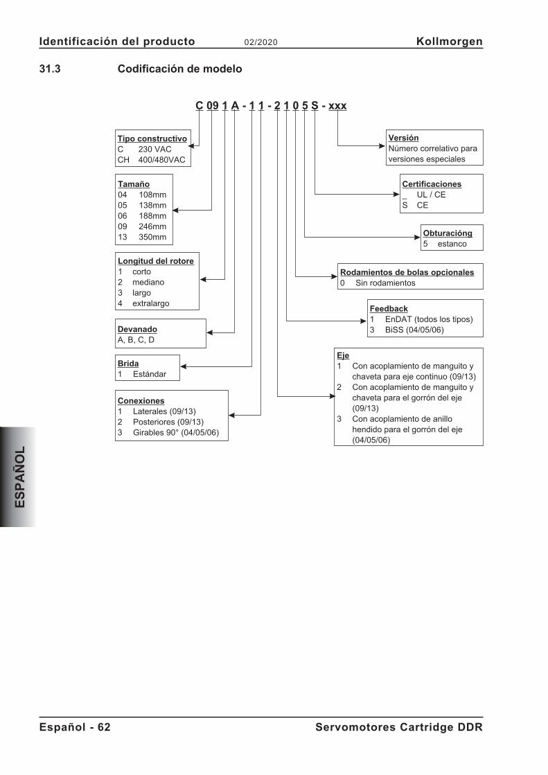
31.3 Codificación de modelo
Español - 62 Servomotores Cartridge DDR
Identificación del producto 02/2020 Kollmorgen
ES
PA
ÑO
L
C 09 1 A - 1 1 - 2 1 0 5 S - xxx
Tipo constructivoC 230 VACCH 400/480VAC
DevanadoA, B, C, D
Tamaño04 108mm05 138mm06 188mm09 246mm13 350mm
Longitud del rotore1 corto2 mediano3 largo4 extralargo
Rodamientos de bolas opcionales0 Sin rodamientos
Obturacióng5 estanco
Certificaciones_ UL / CES CE
VersiónNúmero correlativo paraversiones especiales
Brida1 Estándar
Conexiones1 Laterales (09/13)2 Posteriores (09/13)3 Girables 90° (04/05/06)
Feedback1 EnDAT (todos los tipos)3 BiSS (04/05/06)
Eje1 Con acoplamiento de manguito y
chaveta para eje continuo (09/13)2 Con acoplamiento de manguito y
chaveta para el gorrón del eje(09/13)
3 Con acoplamiento de anillohendido para el gorrón del eje(04/05/06)
32 Descripción técnica
32.1 Datos técnicos generales
Temperatura ambiente 5...+40°C con altura de emplaz. hasta 1000m sobre nivel del(con datos nominales) mar Con temperaturas ambiente superiores a 40°C y con
montaje encapsulado de los motores, tome contacto siemprecon nuestro Departamento de Aplicaciones.
Humedad autorizada 95% humedad relativa, sin formación de rocío(con datos nominales)Reducción de potencia 1%/K en el rango 40°C...50°C hasta 1000 m sobre el nivel del
mar (Corrientes y momentos) con alturas de emplazamientosuperiores a 1000 m sobre el nivel del mar y 40°C
6% a 2000 m sobre el nivel del mar17% a 3000 m sobre el nivel del mar30% a 4000 m sobre el nivel del mar55% a 5000 m sobre el nivel del mar
Sin reducción de potencia a alturas de emplazamientosuperiores a 1000 m sobre el nivel del mar y reducción detemperatura en 10K / 1000m
A partir de la página 73 del capítulo "Technical Data" encontrará los datos técnicos corre-spondientes a cada tipo de motor.
32.1.1 Forma de diseño
El motor se puede montar en cualquier posición, tanto en ejes horizontales como vertica-les.
32.1.2 Brida
Los motores Cartridge DDR no disponen de brida propia, sino que se montan con unacoplamiento de manguito y un anillo de centraje en la brida de la máquina. El anillo deajuste del motor permite el centraje en la brida de la máquina, mientras que el acopla-miento de manguito fija el rotor integrado en el eje de la máquina. El motor no dispone decojinete propio.
Los requisitos de la brida se describen en los capítulos 33.2 y 33.3.
Los motores C(H) 09 y C(H) 13 disponen de una versión con eje hueco abierto para ejesde motor continuos.
Servomotores Cartridge DDR Español - 63
Kollmorgen 02/2020 Descripción técnica
ES
PA
ÑO
L
32.1.3 Tipo de protección
Versión para gorrón de eje (2, 3): IP65 con brida de máquina estancaVersión con eje hueco (1): IP64 con brida de máquina estanca
32.1.4 Clase de material aislante
Los motores cumplen con la clase F de materiales aislantes según IEC 60085 (UL 1446class F).
32.1.5 Superficie
Los motores están cubiertos con la capa del polvo del poliester en negro mate, no siendoresistente a disolventes (Tri, diluyentes, etc.).
32.1.6 Dispositivo protector
El modelo estándar del motor va equipado con un PTC sin potencial. El punto de conex-
ión se encuentra a 155°C � 5%. El PTC no protege contra sobrecargas instantáneasmuy altas. Utilizando nuestro conductor Encoder preconfeccionado, el dispositivo de ter-moprotección está integrado en el sistema de control del servoamplificador digital.
32.1.7 Sistema de conexión
Los motores están equipados con enchufes rectos para el suministro de potencia y lasseñales del Encoder. Según la versión, los enchufes apuntan hacia el lateral o hacia ellado posterior del motor, o bien se pueden girar 90°.
Los contraenchufes no están incluidos en el volumen de suministro. Los cables de poten-cia y de realimentación se suministran preconfeccionados.
32.1.8 Unidad de realimentación (Feedback)
C(H) yyxx-xx-x1xxEncoder SinCos de alta resolución, monovuelta, ECN1313 (2048 periodo), EnDat
C(H) 04xx-xx-x3xx, C(H) 05xx-xx-x3xx und C(H) 06xx-xx-x3xxEncoder SinCos de alta resolución, monovuelta, Hengstler ACURO AD36 (2048 periodo);BiSS
Español - 64 Servomotores Cartridge DDR
Descripción técnica 02/2020 Kollmorgen
ES
PA
ÑO
L
33 Instalación mecánica
Los dibujos de la dimensión se pueden encontrar en capítulo "Dimension Drawings" p.79.
33.1 Instrucciones importantes
Solamente los profesionales con conocimientos de mecánica están autorizados a mon-tar.
El montaje y cableado de los motores se realizará siempre sin tensión, es decir,ninguna de las tensiones de servicio del aparato a conectar deberá estaractivada.
Tocar contactos expuestos comporta peligro de muerte y riesgos graves para lasalud.
Asegúrese de que la desconexión del armario de distribución sea segura(bloqueo, rótulos de advertencia, etc.). Las diferentes tensiones se conectaránen la primera puesta en funcionamiento.
El lado de montaje del motor es magnético y atrae el hierro. Cubra el extremo del motorpara evitar que se ensucie.
� Proteja los motores contra esfuerzos excesivos.Especialmente durante el transporte y la manipulación, no se deberán doblar com-ponentes, ni modificar las distancias de aislamiento.
� El lugar de instalación se encontrará libre de materiales conductores y agresivos.Antes de realizar el montaje encapsulado, consulte a nuestro Departamento de Apli-caciones.
� Monte el motor siguiendo las instrucciones de la página 66 y siguientes.Durante el montaje procure que el motor no se fije mecánicamente desalineado.
� Asegúrese de la ventilación sin obstáculos de los motores, respetando la tempera-tura ambiente y la temperatura de la brida. Con temperaturas superiores a 40 °C,consulte previamente con nuestro Departamento de Aplicaciones.
Servomotores Cartridge DDR Español - 65
Kollmorgen 02/2020 Instalación mecánica
ES
PA
ÑO
LE
SP
AÑ
OL
PELIGRO
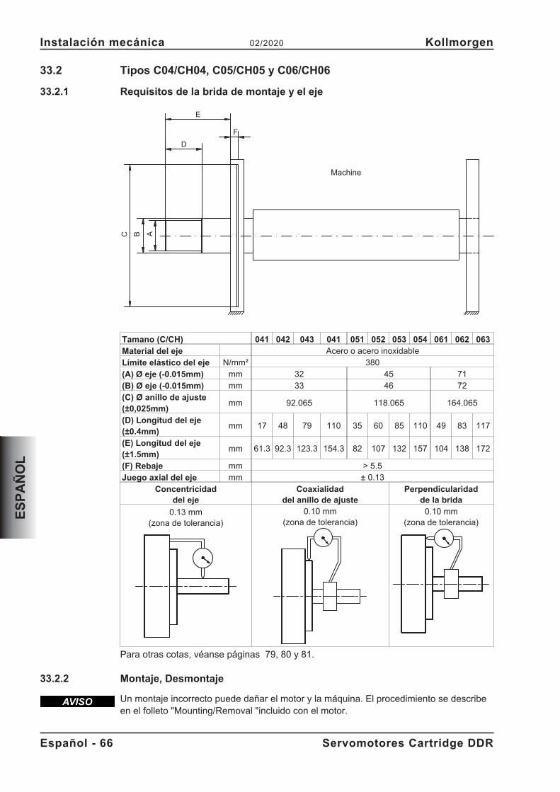
33.2 Tipos C04/CH04, C05/CH05 y C06/CH06
33.2.1 Requisitos de la brida de montaje y el eje
Tamano (C/CH) 041 042 043 041 051 052 053 054 061 062 063
Material del eje Acero o acero inoxidableLímite elástico del eje N/mm² 380(A) Ø eje (-0.015mm) mm 32 45 71(B) Ø eje (-0.015mm) mm 33 46 72(C) Ø anillo de ajuste(±0,025mm)
mm 92.065 118.065 164.065
(D) Longitud del eje(±0.4mm)
mm 17 48 79 110 35 60 85 110 49 83 117
(E) Longitud del eje(±1.5mm)
mm 61.3 92.3 123.3 154.3 82 107 132 157 104 138 172
(F) Rebaje mm > 5.5Juego axial del eje mm ± 0.13
Concentricidaddel eje
Coaxialidaddel anillo de ajuste
Perpendicularidadde la brida
0.13 mm(zona de tolerancia)
0.10 mm(zona de tolerancia)
0.10 mm(zona de tolerancia)
Para otras cotas, véanse páginas 79, 80 y 81.
33.2.2 Montaje, Desmontaje
Un montaje incorrecto puede dañar el motor y la máquina. El procedimiento se describeen el folleto "Mounting/Removal "incluido con el motor.
Español - 66 Servomotores Cartridge DDR
Instalación mecánica 02/2020 Kollmorgen
ES
PA
ÑO
L
BCE
A
F
D
Machine
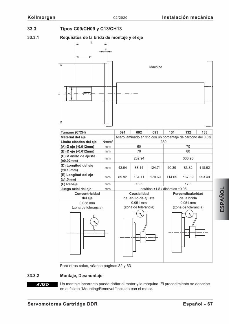
33.3 Tipos C09/CH09 y C13/CH13
33.3.1 Requisitos de la brida de montaje y el eje
Tamano (C/CH) 091 092 093 131 132 133
Material del eje Acero laminado en frío con un porcentaje de carbono del 0,3%Límite elástico del eje N/mm² 380(A) Ø eje (-0.012mm) mm 60 70(B) Ø eje (-0.012mm) mm 70 80(C) Ø anillo de ajuste(±0.02mm)
mm 232.94 333.96
(D) Longitud del eje(±0.13mm)
mm 43.94 88.14 124.71 40.39 83.82 118.62
(E) Longitud del eje(±1.5mm)
mm 89.92 134.11 170.69 114.05 167.89 253.49
(F) Rebaje mm 13.5 17.8Juego axial del eje mm estático ±1.5 / dinámico ±0.05
Concentricidaddel eje
Coaxialidaddel anillo de ajuste
Perpendicularidadde la brida
0.038 mm(zona de tolerancia)
0.051 mm(zona de tolerancia)
0.051 mm(zona de tolerancia)
Para otras cotas, véanse páginas 82 y 83.
33.3.2 Montaje, Desmontaje
Un montaje incorrecto puede dañar el motor y la máquina. El procedimiento se describeen el folleto "Mounting/Removal "incluido con el motor.
Servomotores Cartridge DDR Español - 67
Kollmorgen 02/2020 Instalación mecánica
ES
PA
ÑO
L
BC
E
A
F
Machine
34 Instalación eléctrica
Los esquemas eléctricos se pueden encontrar en capítulo "Wiring Diagrams" de lapag.79.
34.1 Instrucciones importantes
Solamente los profesionales con conocimientos de electrotecnia están autorizados a ca-blear el motor.
El montaje y cableado de los motores se realizará siempre sin tensión, es decir,ninguna de las tensiones de servicio del aparato a conectar deberá estaractivada. Tocar contactos expuestos comporta peligro de muerte y riesgosgraves para la salud.
Asegúrese de que la desconexión del armario de distribución sea segura(bloqueo, rótulos de advertencia, etc.). Las diferentes tensiones se conectaránen la primera puesta en funcionamiento.
No manipule nunca las conexiones eléctricas de los motores cuando seencuentren bajo tensión. Riesgo de choque eléctrico! En caso de accidente sepueden generar chispazos que dañen a las personas y a los contactos.
Las cargas residuales en los condensadores del amplificador con nivelespeligrosos de hasta 10 minutos después de desconectar el cable dealimentación. Las conexiones de control y de potencia pueden provocartensión, incluso aunque el motor no esté girando.
Mida la tensión en el circuito intermedio y espere hasta que haya descendidopor debajo de 50 V.
El símbolo de masa�, que se encuentra en todos los planos de conexión, indica quedebe asegurarse de realizar una conexión en el armario de distribución con la mayor su-perficie posible conductora de electricidad, entre el aparato que lleva la indicación y laplaca de montaje. Esta conexión hará posible la derivación de interferencias de alta fre-cuencia y no debe confundirse con la marca PE (medida de protección según EN60204). Respete también las indicaciones en los planos de conexión de las manual deinstalación y de puesta en funcionamiento del servoamplificador utilizado.
34.2 Conexión de los motores con conducciones preconfeccionadas
� Realice el cableado cumpliendo los reglamentos y normas vigentes.� Para las conexiones de potencia y de retorno, utilice exclusivamente los conduccio-
nes preconfeccionadas y protegidas de Kollmorgen.� Los apantallamientos mal colocados producen siempre a interferencias electromag-
néticas y degradar el rendimiento del sistema.� La longitud máxima del conductor se define en el manual de producto del servoam-
plificador utilizado.
Para una descripción detallada de cables premontados, refiera por favor a los manualesaccesorios.
Español - 68 Servomotores Cartridge DDR
Instalación eléctrica 02/2020 Kollmorgen
ES
PA
ÑO
L
PELIGRO
34.3 Guía de instalación eléctrica
� Compruebe la correspondencia entre el servoamplificador y el motor. Compare latensión nominal y la corriente nominal de los aparatos. Realice el cableado confor-me al cuadro de conexiones de las Instrucciones de instalación y de puesta en fun-cionamiento del servoamplificador. Las conexiones del motor se encuentran en ca-pítulo "Wiring Diagrams" pag.79.
� Realice el tendido de todos las conducciones de alta tensión con sección suficientesegún EN 60204. En los datos técnicos se incluyen las secciones recomendadas.
� En función del tipo de servoamplificador utilizado, con cables de motor largos(>25m) debe conectarse una bobina de motor (3YL o 3YLN) en el conductor del mo-tor (véase el manual de producto del servoamplificador y el manual de accesorios).
� Asegúrese de que la toma de tierra del servoamplificador y del motor esté perfecta-mente instalada. Véanse la adecuada protección de compatibilidad electromagnéti-ca y de puesta a tierra en las Instrucciones de instalación del servoamplificador utili-zado. Ponga a tierra la placa de montaje y el bloque del motor.
� Cableado— Tienda los cables de potencia y de control bien separados— Conecte el codificador— Conecte los cables del motor cerca del servoamplificador— Apantallamientos a ambos lados en bornes de protección o en el enchufe de
CEM� Realice apantallamientos de gran superficie (baja resistencia) a través de cajas de
enchufe metalizadas, o bien, de uniones de cable roscadas compatibles electro-magnéticamente.
� Requisitos al material de cables:CapacidadCable del motor - menor que 150 pF/mCable Encoder - menor que 120 pF/m
Servomotores Cartridge DDR Español - 69
Kollmorgen 02/2020 Instalación eléctrica
ES
PA
ÑO
L
35 Puesta en funcionamento
35.1 Instrucciones importantes
Solamente los profesionales con amplios conocimientos de electrotecnia y de técnicasde accionamiento están autorizados a la puesta en funcionamiento del conjunto servo-amplificador-motor.
Se producen tensiones peligrosas de hasta 900V. Riesgo de descarga eléctrica!Compruebe que todas las piezas de conexión que conducen tensión esténprotegidas contra cualquier posible contacto. No manipule nunca las conexioneseléctricas de los motores cuando se encuentren bajo tensión. Las cargasresiduales en los condensadores del amplificador con niveles peligrosos dehasta 10 minutos después de desconectar el cable de alimentación. Mida latensión en el circuito intermedio y espere hasta que haya descendido por debajode 50 V. Las conexiones de control y de potencia pueden provocar tensión,incluso aunque el motor no esté girando.
La temperatura de la superficie del motor puede alcanzar 100 °C durante elservicio. Peligro de quemaduras leves! Mida la temperatura del motor.Espere a que la temperatura haya descendido a 40 °C antes de tocar el motorcon las manos
No hay que descartar que durante la puesta en funcionamiento el acciona-miento realice un movimiento imprevisto. Asegúrese de que cualquiermovimiento no deseado de la unidad no puede causar peligro para personas obienes. Las medidas que habrá de observar en este aspecto en su aplicaciónresultarán de la valoración de riesgos de dicha aplicación.
35.2 Guía de puesta en funcionamento
La forma de proceder en la puesta en accionamiento se describe a modo de ejemplo.Dependiendo del tipo de puesta en servicio de los aparatos puede ser adecuado o nece-sario un procedimiento u otro.� Compruebe el montaje y la alineación del motor.� Compruebe el cableado y las conexiones del motor y del servoamplificador. Com-
pruebe la correcta puesta a tierra.� Compruebe si el rotor del motor gira libremente e si se escuchan ruidos de fricción.� Compruebe si se han tomado todas las medidas de protección contra contactos
para las piezas móviles y las conductoras de tensión.� Realice todas las comprobaciones específicas y necesarias para su equipo.� Conforme a las Instrucciones de puesta en funcionamiento del servoamplificador,
ponga ahora en marcha el accionamiento.� En sistemas de varios ejes, ponga en marcha, una a una, cada una de las unidades
de accionamiento servoamplificador-motor.
Español - 70 Servomotores Cartridge DDR
Puesta en funcionamento 02/2020 Kollmorgen
ES
PA
ÑO
L
PELIGRO
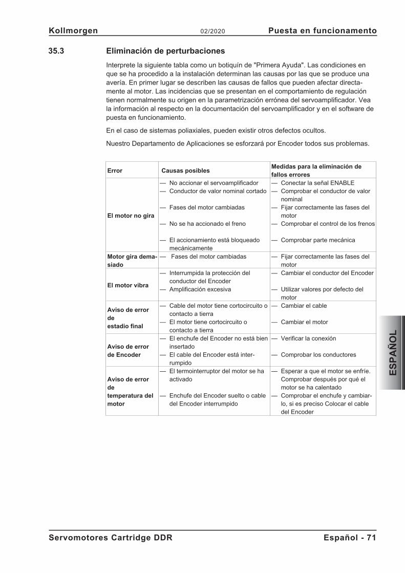
35.3 Eliminación de perturbaciones
Interprete la siguiente tabla como un botiquín de "Primera Ayuda". Las condiciones enque se ha procedido a la instalación determinan las causas por las que se produce unaavería. En primer lugar se describen las causas de fallos que pueden afectar directa-mente al motor. Las incidencias que se presentan en el comportamiento de regulacióntienen normalmente su origen en la parametrización errónea del servoamplificador. Veala información al respecto en la documentación del servoamplificador y en el software depuesta en funcionamiento.
En el caso de sistemas poliaxiales, pueden existir otros defectos ocultos.
Nuestro Departamento de Aplicaciones se esforzará por Encoder todos sus problemas.
Error Causas posiblesMedidas para la eliminación defallos errores
El motor no gira
— No accionar el servoamplificador— Conductor de valor nominal cortado
— Fases del motor cambiadas
— No se ha accionado el freno
— El accionamiento está bloqueadomecánicamente
— Conectar la señal ENABLE— Comprobar el conductor de valor
nominal— Fijar correctamente las fases del
motor— Comprobar el control de los frenos
— Comprobar parte mecánica
Motor gira dema-siado
— Fases del motor cambiadas — Fijar correctamente las fases delmotor
El motor vibra
— Interrumpida la protección delconductor del Encoder
— Amplificación excesiva
— Cambiar el conductor del Encoder
— Utilizar valores por defecto delmotor
Aviso de errordeestadio final
— Cable del motor tiene cortocircuito ocontacto a tierra
— El motor tiene cortocircuito ocontacto a tierra
— Cambiar el cable
— Cambiar el motor
Aviso de errorde Encoder
— El enchufe del Encoder no está bieninsertado
— El cable del Encoder está inter-rumpido
— Verificar la conexión
— Comprobar los conductores
Aviso de errordetemperatura delmotor
— El termointerruptor del motor se haactivado
— Enchufe del Encoder suelto o cabledel Encoder interrumpido
— Esperar a que el motor se enfríe.Comprobar después por qué elmotor se ha calentado
— Comprobar el enchufe y cambiar-lo, si es preciso Colocar el cabledel Encoder
Servomotores Cartridge DDR Español - 71
Kollmorgen 02/2020 Puesta en funcionamento
ES
PA
ÑO
L
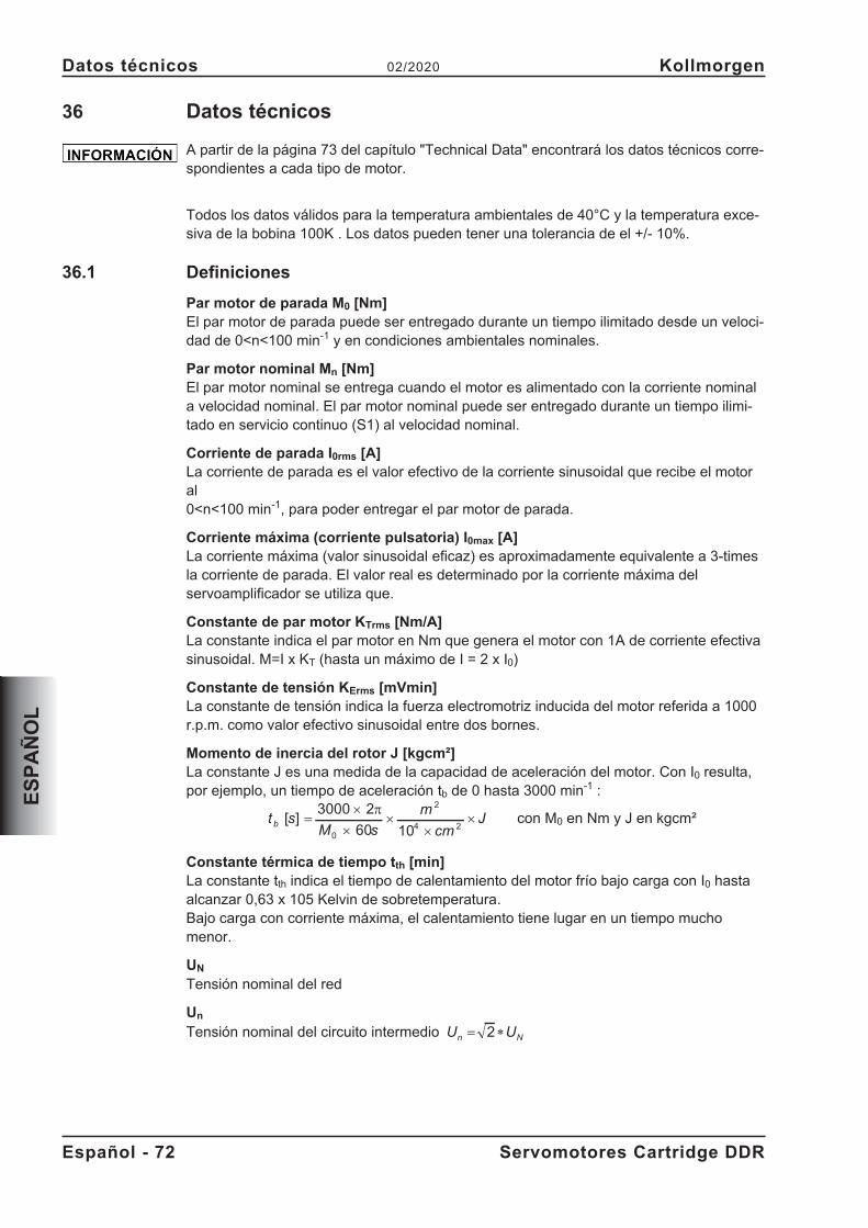
36 Datos técnicos
A partir de la página 73 del capítulo "Technical Data" encontrará los datos técnicos corre-spondientes a cada tipo de motor.
Todos los datos válidos para la temperatura ambientales de 40°C y la temperatura exce-siva de la bobina 100K . Los datos pueden tener una tolerancia de el +/- 10%.
36.1 Definiciones
Par motor de parada M0 [Nm]El par motor de parada puede ser entregado durante un tiempo ilimitado desde un veloci-dad de 0<n<100 min-1 y en condiciones ambientales nominales.
Par motor nominal Mn [Nm]El par motor nominal se entrega cuando el motor es alimentado con la corriente nominala velocidad nominal. El par motor nominal puede ser entregado durante un tiempo ilimi-tado en servicio continuo (S1) al velocidad nominal.
Corriente de parada I0rms [A]La corriente de parada es el valor efectivo de la corriente sinusoidal que recibe el motoral0<n<100 min-1, para poder entregar el par motor de parada.
Corriente máxima (corriente pulsatoria) I0max [A]La corriente máxima (valor sinusoidal eficaz) es aproximadamente equivalente a 3-timesla corriente de parada. El valor real es determinado por la corriente máxima delservoamplificador se utiliza que.
Constante de par motor KTrms [Nm/A]La constante indica el par motor en Nm que genera el motor con 1A de corriente efectivasinusoidal. M=I x KT (hasta un máximo de I = 2 x I0)
Constante de tensión KErms [mVmin]La constante de tensión indica la fuerza electromotriz inducida del motor referida a 1000r.p.m. como valor efectivo sinusoidal entre dos bornes.
Momento de inercia del rotor J [kgcm²]La constante J es una medida de la capacidad de aceleración del motor. Con I0 resulta,por ejemplo, un tiempo de aceleración tb de 0 hasta 3000 min-1 :
t sM s
m
cmJ
b[ ] �
�
��
��
3000 2
60 100
2
4 2
�con M0 en Nm y J en kgcm²
Constante térmica de tiempo tth [min]La constante tth indica el tiempo de calentamiento del motor frío bajo carga con I0 hastaalcanzar 0,63 x 10⁵ Kelvin de sobretemperatura.Bajo carga con corriente máxima, el calentamiento tiene lugar en un tiempo muchomenor.
UN
Tensión nominal del red
Un
Tensión nominal del circuito intermedio U Un N
� �2
Español - 72 Servomotores Cartridge DDR
Datos técnicos 02/2020 Kollmorgen
ES
PA
ÑO
L
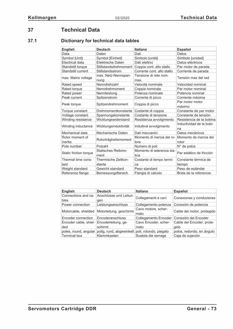
37 Technical Data
37.1 Dictionary for technical data tables
English Deutsch Italiano EspañolData Daten Dati DatosSymbol [Unit] Symbol [Einheit] Simbolo [unità] Símbolo [unidad]Electrical data Elektrische Daten Dati elettrici Datos eléctricosStandstill torque Stillstandsdrehmoment Coppia cont. allo stallo Par motor de paradaStandstill current Stillstandsstrom Corrente cont. allo stallo Corriente de parada
max. Mains voltagemax. Netz-Nennspan-nung
Tensione di rete nom.max.
Tensión max del red
Rated speed Nenndrehzahl Velocità nominale Velocidad nominalRated torque Nenndrehmoment Coppia nominale Par motor nominalRated power Nennleistung Potenza nominale Potencia nominalPeak current Spitzenstrom Corrente di picco Corriente máxima
Peak torque Spitzendrehmoment Coppia di piccoPar motor motormáximo
Torque constant Drehmomentkonstante Costante di coppia Constante de par motorVoltage constant Spannungskonstante Costante di tensione Constante de tensiónWinding resistance Wicklungswiderstand Resistenza avvolgimento Resistencia de la bobina
Winding inductance Wicklungsinduktivität Induttivà avvolgimentoInductividad de la bobi-na
Mechanical data Mechanische Daten Dati meccanici Datos mecánicosRotor moment ofinertia
RotorträgheitsmomentMomento di inerzia del ro-tore
Momento de inercia delrotor
Pole number Polzahl Numero di poli N° de polos
Static friction torqueStatisches Reibmo-ment
Momento di aderenza sta-tica
Par estático de fricción
Thermal time cons-tant
Thermische Zeitkon-stante
Costante di tempo termi-ca
Constante térmica detiempo
Weight standard Gewicht standard Peso standard Peso de estándarReference flange Bemessungsflansch Flangia di calcolo Brida de la referencia
English Deutsch Italiano EspañolConnections and ca-bles
Anschlüsse und Leitun-gen
Collegamenti e cavi Conexiones y conductores
Power connection Leistungsanschluss Collegamento potenza Conexión de potencia
Motorcable, shielded Motorleitung, geschirmtCavo motore, scher-mato
Cable del motor, protegido
Encoder connection Encoderanschluss Collegamento Encoder Conexión del EncoderEncoder cable, shiel-ded
Encoderleitung, ge-schirmt
Cavo Encoder, scher-mato
Cable del Encoder, prote-gido
poles, round, angular polig, rund, abgewinkelt poli, rotondo, piegato polos, redondo, en ánguloTerminal box Klemmkasten Scatola die serrage Caja de sujeción
Servomotors Cartridge DDR General - 73
Kollmorgen 02/2020 Technical Data
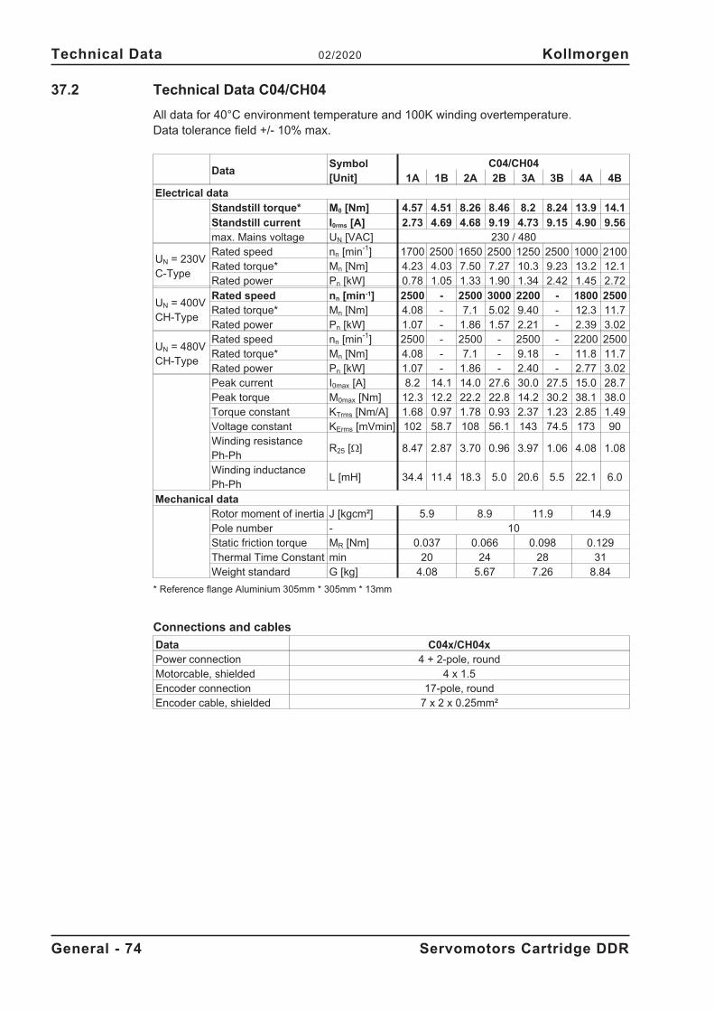
37.2 Technical Data C04/CH04
All data for 40°C environment temperature and 100K winding overtemperature.Data tolerance field +/- 10% max.
DataSymbol[Unit]
C04/CH04
1A 1B 2A 2B 3A 3B 4A 4B
Electrical data
Standstill torque* M0 [Nm] 4.57 4.51 8.26 8.46 8.2 8.24 13.9 14.1
Standstill current I0rms [A] 2.73 4.69 4.68 9.19 4.73 9.15 4.90 9.56max. Mains voltage UN [VAC] 230 / 480
UN = 230VC-Type
Rated speed nn [min-1] 1700 2500 1650 2500 1250 2500 1000 2100Rated torque* Mn [Nm] 4.23 4.03 7.50 7.27 10.3 9.23 13.2 12.1Rated power Pn [kW] 0.78 1.05 1.33 1.90 1.34 2.42 1.45 2.72
UN = 400VCH-Type
Rated speed nn [min-1] 2500 - 2500 3000 2200 - 1800 2500Rated torque* Mn [Nm] 4.08 - 7.1 5.02 9.40 - 12.3 11.7Rated power Pn [kW] 1.07 - 1.86 1.57 2.21 - 2.39 3.02
UN = 480VCH-Type
Rated speed nn [min-1] 2500 - 2500 - 2500 - 2200 2500Rated torque* Mn [Nm] 4.08 - 7.1 - 9.18 - 11.8 11.7Rated power Pn [kW] 1.07 - 1.86 - 2.40 - 2.77 3.02Peak current I0max [A] 8.2 14.1 14.0 27.6 30.0 27.5 15.0 28.7Peak torque M0max [Nm] 12.3 12.2 22.2 22.8 14.2 30.2 38.1 38.0Torque constant KTrms [Nm/A] 1.68 0.97 1.78 0.93 2.37 1.23 2.85 1.49Voltage constant KErms [mVmin] 102 58.7 108 56.1 143 74.5 173 90Winding resistancePh-Ph
R25 [�] 8.47 2.87 3.70 0.96 3.97 1.06 4.08 1.08
Winding inductancePh-Ph
L [mH] 34.4 11.4 18.3 5.0 20.6 5.5 22.1 6.0
Mechanical dataRotor moment of inertia J [kgcm²] 5.9 8.9 11.9 14.9Pole number - 10Static friction torque MR [Nm] 0.037 0.066 0.098 0.129Thermal Time Constant min 20 24 28 31Weight standard G [kg] 4.08 5.67 7.26 8.84
* Reference flange Aluminium 305mm * 305mm * 13mm
Connections and cables
Data C04x/CH04xPower connection 4 + 2-pole, roundMotorcable, shielded 4 x 1.5Encoder connection 17-pole, roundEncoder cable, shielded 7 x 2 x 0.25mm²
General - 74 Servomotors Cartridge DDR
Technical Data 02/2020 Kollmorgen
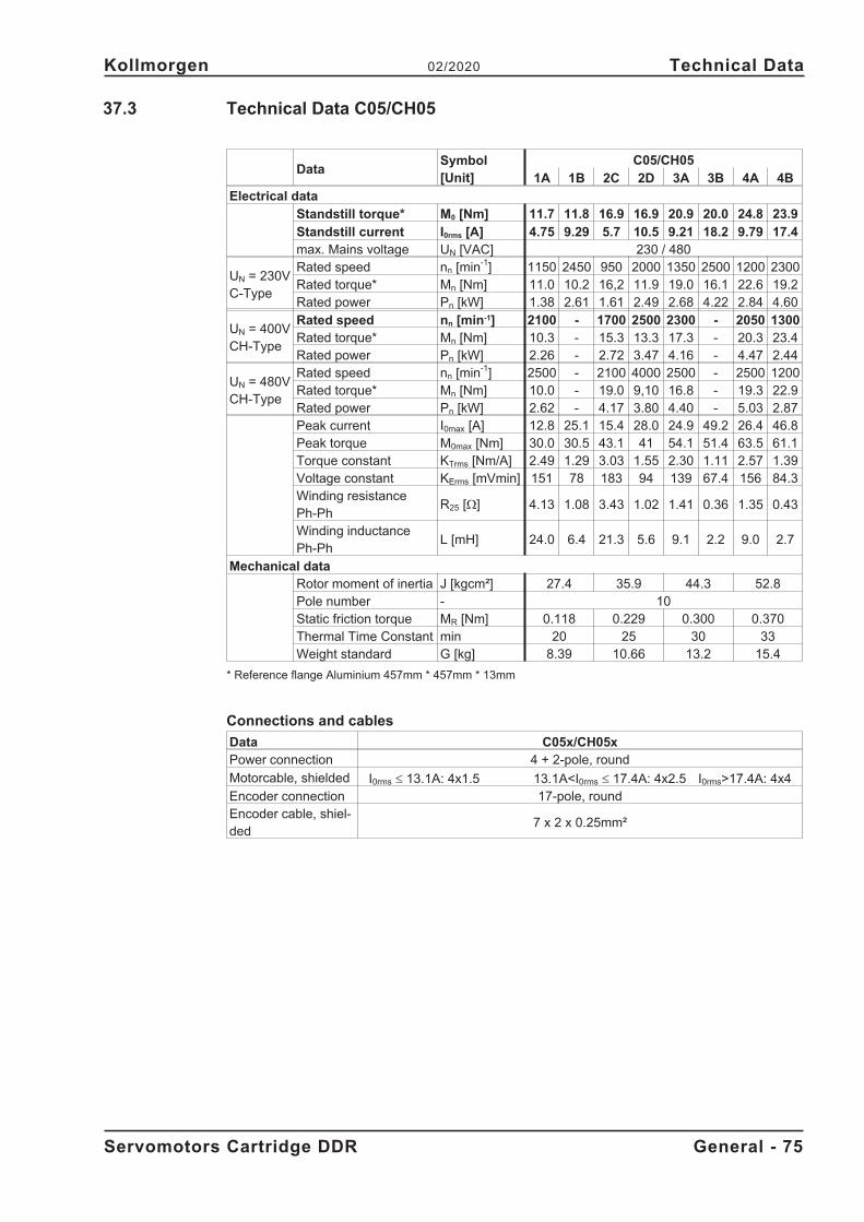
37.3 Technical Data C05/CH05
DataSymbol[Unit]
C05/CH05
1A 1B 2C 2D 3A 3B 4A 4B
Electrical data
Standstill torque* M0 [Nm] 11.7 11.8 16.9 16.9 20.9 20.0 24.8 23.9
Standstill current I0rms [A] 4.75 9.29 5.7 10.5 9.21 18.2 9.79 17.4max. Mains voltage UN [VAC] 230 / 480
UN = 230VC-Type
Rated speed nn [min-1] 1150 2450 950 2000 1350 2500 1200 2300Rated torque* Mn [Nm] 11.0 10.2 16,2 11.9 19.0 16.1 22.6 19.2Rated power Pn [kW] 1.38 2.61 1.61 2.49 2.68 4.22 2.84 4.60
UN = 400VCH-Type
Rated speed nn [min-1] 2100 - 1700 2500 2300 - 2050 1300Rated torque* Mn [Nm] 10.3 - 15.3 13.3 17.3 - 20.3 23.4Rated power Pn [kW] 2.26 - 2.72 3.47 4.16 - 4.47 2.44
UN = 480VCH-Type
Rated speed nn [min-1] 2500 - 2100 4000 2500 - 2500 1200Rated torque* Mn [Nm] 10.0 - 19.0 9,10 16.8 - 19.3 22.9Rated power Pn [kW] 2.62 - 4.17 3.80 4.40 - 5.03 2.87Peak current I0max [A] 12.8 25.1 15.4 28.0 24.9 49.2 26.4 46.8Peak torque M0max [Nm] 30.0 30.5 43.1 41 54.1 51.4 63.5 61.1Torque constant KTrms [Nm/A] 2.49 1.29 3.03 1.55 2.30 1.11 2.57 1.39Voltage constant KErms [mVmin] 151 78 183 94 139 67.4 156 84.3Winding resistancePh-Ph
R25 [�] 4.13 1.08 3.43 1.02 1.41 0.36 1.35 0.43
Winding inductancePh-Ph
L [mH] 24.0 6.4 21.3 5.6 9.1 2.2 9.0 2.7
Mechanical dataRotor moment of inertia J [kgcm²] 27.4 35.9 44.3 52.8Pole number - 10Static friction torque MR [Nm] 0.118 0.229 0.300 0.370Thermal Time Constant min 20 25 30 33Weight standard G [kg] 8.39 10.66 13.2 15.4
* Reference flange Aluminium 457mm * 457mm * 13mm
Connections and cables
Data C05x/CH05xPower connection 4 + 2-pole, round
Motorcable, shielded I0rms � 13.1A: 4x1.5 13.1A<I0rms � 17.4A: 4x2.5 I0rms>17.4A: 4x4Encoder connection 17-pole, roundEncoder cable, shiel-ded
7 x 2 x 0.25mm²
Servomotors Cartridge DDR General - 75
Kollmorgen 02/2020 Technical Data
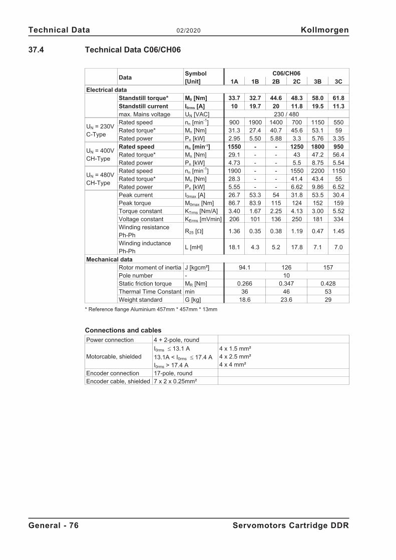
37.4 Technical Data C06/CH06
DataSymbol[Unit]
C06/CH06
1A 1B 2B 2C 3B 3C
Electrical data
Standstill torque* M0 [Nm] 33.7 32.7 44.6 48.3 58.0 61.8
Standstill current I0rms [A] 10 19.7 20 11.8 19.5 11.3max. Mains voltage UN [VAC] 230 / 480
UN = 230VC-Type
Rated speed nn [min-1] 900 1900 1400 700 1150 550Rated torque* Mn [Nm] 31.3 27.4 40.7 45.6 53.1 59Rated power Pn [kW] 2.95 5.50 5.88 3.3 5.76 3.35
UN = 400VCH-Type
Rated speed nn [min-1] 1550 - - 1250 1800 950Rated torque* Mn [Nm] 29.1 - - 43 47.2 56.4Rated power Pn [kW] 4.73 - - 5.5 8.75 5.54
UN = 480VCH-Type
Rated speed nn [min-1] 1900 - - 1550 2200 1150Rated torque* Mn [Nm] 28.3 - - 41.4 43.4 55Rated power Pn [kW] 5.55 - - 6.62 9.86 6.52Peak current I0max [A] 26.7 53.3 54 31.8 53.5 30.4Peak torque M0max [Nm] 86.7 83.9 115 124 152 159Torque constant KTrms [Nm/A] 3.40 1.67 2.25 4.13 3.00 5.52Voltage constant KErms [mVmin] 206 101 136 250 181 334Winding resistancePh-Ph
R25 [�] 1.36 0.35 0.38 1.19 0.47 1.45
Winding inductancePh-Ph
L [mH] 18.1 4.3 5.2 17.8 7.1 7.0
Mechanical dataRotor moment of inertia J [kgcm²] 94.1 126 157Pole number - 10Static friction torque MR [Nm] 0.266 0.347 0.428Thermal Time Constant min 36 46 53Weight standard G [kg] 18.6 23.6 29
* Reference flange Aluminium 457mm * 457mm * 13mm
Connections and cables
Power connection 4 + 2-pole, round
Motorcable, shieldedI0rms � 13.1 A
13.1A < I0rms � 17.4 AI0rms > 17.4 A
4 x 1.5 mm²4 x 2.5 mm²4 x 4 mm²
Encoder connection 17-pole, roundEncoder cable, shielded 7 x 2 x 0.25mm²
General - 76 Servomotors Cartridge DDR
Technical Data 02/2020 Kollmorgen
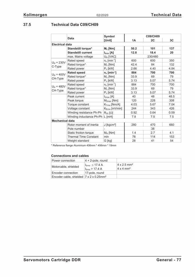
37.5 Technical Data C09/CH09
DataSymbol[Unit]
C09/CH09
1A 2C 3C
Electrical data
Standstill torque* M0 [Nm] 50.2 101 137
Standstill current I0rms [A] 12.8 18.4 20max. Mains voltage UN [VAC] 230/480
UN = 230VC-Type
Rated speed nn [min-1] 600 600 350Rated torque* Mn [Nm] 42.4 84 132Rated power Pn [kW] 2.66 4.40 4.84
UN = 400VCH-Type
Rated speed nn [min-1] 884 700 700Rated torque* Mn [Nm] 33.9 69 79Rated power Pn [kW] 3.13 5.07 5.74
UN = 480VCH-Type
Rated speed nn [min-1] 884 700 700Rated torque* Mn [Nm] 33.9 69 79Rated power Pn [kW] 3.13 5.07 5.74Peak current I0max [A] 40 48 48.5Peak torque M0max [Nm] 120 228 308Torque constant KTrms [Nm/A] 4.03 5.67 7.04Voltage constant KErms [mVmin] 244 343 426
Winding resistance Ph-Ph R25 [�] 0.92 0.64 0.59
Winding inductance Ph-Ph L [mH] 7.8 7.5 7.5Mechanical data
Rotor moment of inertia J [kgcm²] 280 470 660Pole number - 38Static friction torque MR [Nm] 1.4 2.7 4.1Thermal Time Constant min 78 114 153Weight standard G [kg] 28 41 54
* Reference flange Aluminium 406mm * 406mm * 19mm
Connections and cables
Power connection 4 + 2-pole, round
Motorcable, shieldedI0rms � 17.4 AI0rms > 17.4 A
4 x 2.5 mm²4 x 4 mm²
Encoder connection 17-pole, roundEncoder cable, shielded 7 x 2 x 0.25mm²
Servomotors Cartridge DDR General - 77
Kollmorgen 02/2020 Technical Data
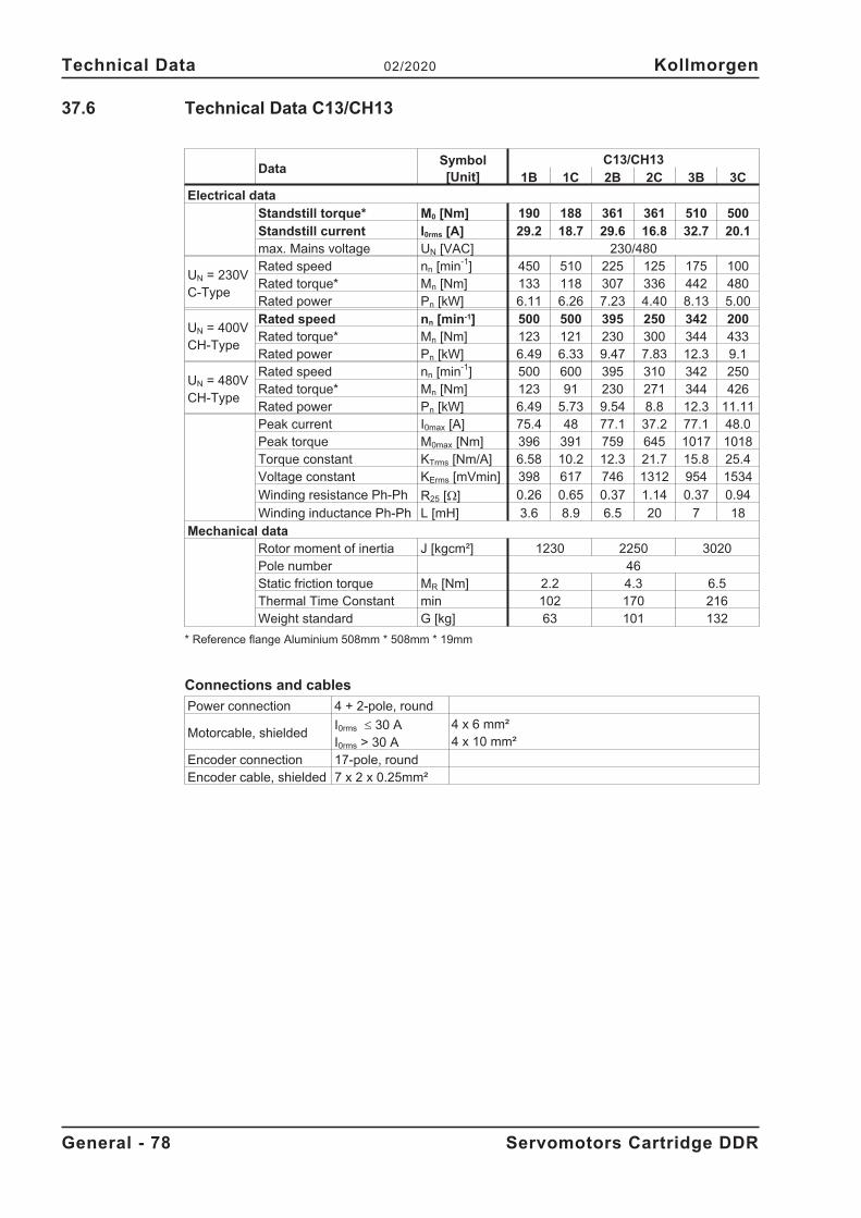
37.6 Technical Data C13/CH13
DataSymbol[Unit]
C13/CH13
1B 1C 2B 2C 3B 3C
Electrical data
Standstill torque* M0 [Nm] 190 188 361 361 510 500
Standstill current I0rms [A] 29.2 18.7 29.6 16.8 32.7 20.1max. Mains voltage UN [VAC] 230/480
UN = 230VC-Type
Rated speed nn [min-1] 450 510 225 125 175 100Rated torque* Mn [Nm] 133 118 307 336 442 480Rated power Pn [kW] 6.11 6.26 7.23 4.40 8.13 5.00
UN = 400VCH-Type
Rated speed nn [min-1] 500 500 395 250 342 200Rated torque* Mn [Nm] 123 121 230 300 344 433Rated power Pn [kW] 6.49 6.33 9.47 7.83 12.3 9.1
UN = 480VCH-Type
Rated speed nn [min-1] 500 600 395 310 342 250Rated torque* Mn [Nm] 123 91 230 271 344 426Rated power Pn [kW] 6.49 5.73 9.54 8.8 12.3 11.11Peak current I0max [A] 75.4 48 77.1 37.2 77.1 48.0Peak torque M0max [Nm] 396 391 759 645 1017 1018Torque constant KTrms [Nm/A] 6.58 10.2 12.3 21.7 15.8 25.4Voltage constant KErms [mVmin] 398 617 746 1312 954 1534
Winding resistance Ph-Ph R25 [�] 0.26 0.65 0.37 1.14 0.37 0.94
Winding inductance Ph-Ph L [mH] 3.6 8.9 6.5 20 7 18Mechanical data
Rotor moment of inertia J [kgcm²] 1230 2250 3020Pole number 46Static friction torque MR [Nm] 2.2 4.3 6.5Thermal Time Constant min 102 170 216Weight standard G [kg] 63 101 132
* Reference flange Aluminium 508mm * 508mm * 19mm
Connections and cables
Power connection 4 + 2-pole, round
Motorcable, shieldedI0rms � 30 AI0rms > 30 A
4 x 6 mm²4 x 10 mm²
Encoder connection 17-pole, roundEncoder cable, shielded 7 x 2 x 0.25mm²
General - 78 Servomotors Cartridge DDR
Technical Data 02/2020 Kollmorgen
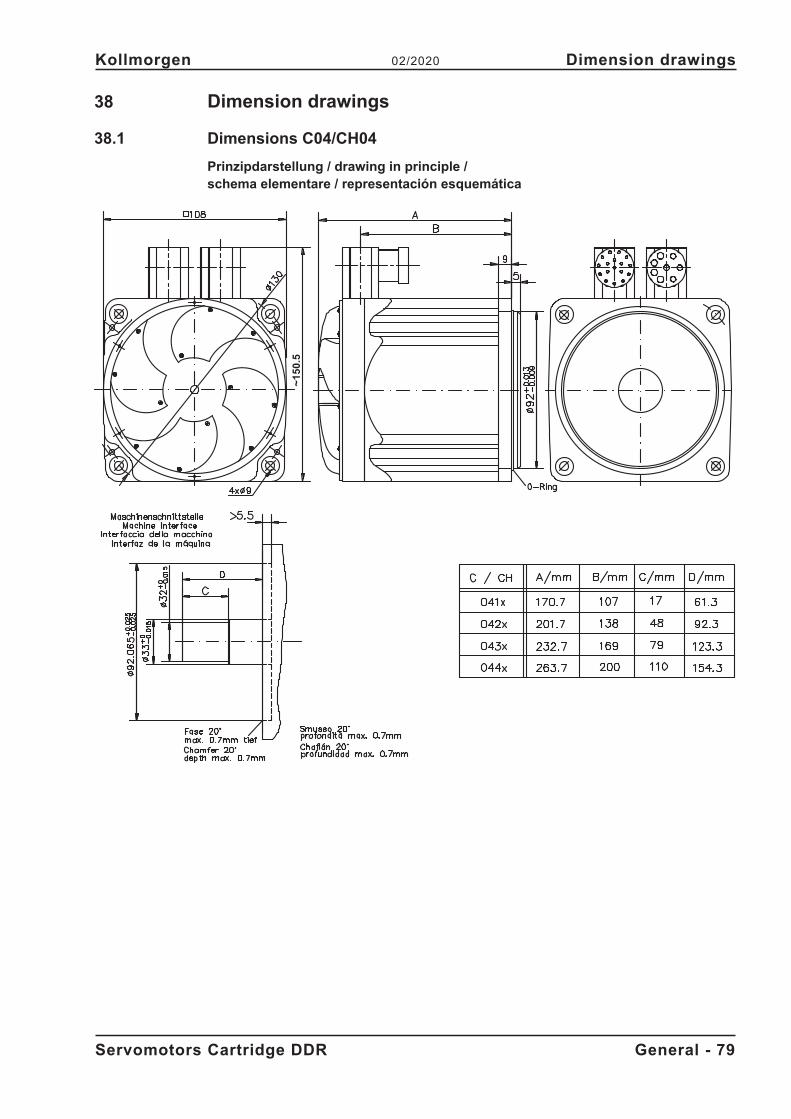
38 Dimension drawings
38.1 Dimensions C04/CH04
Prinzipdarstellung / drawing in principle /schema elementare / representación esquemática
Servomotors Cartridge DDR General - 79
Kollmorgen 02/2020 Dimension drawings
~1
50
.5
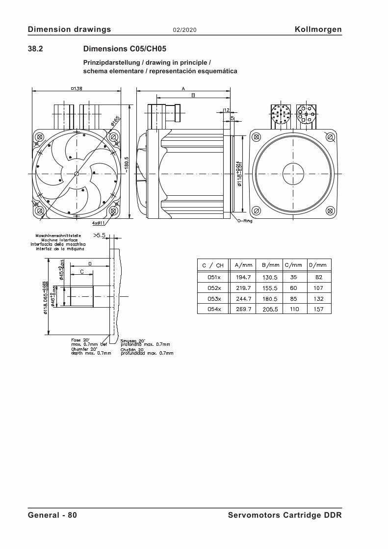
38.2 Dimensions C05/CH05
Prinzipdarstellung / drawing in principle /schema elementare / representación esquemática
General - 80 Servomotors Cartridge DDR
Dimension drawings 02/2020 Kollmorgen
~1
80
.5
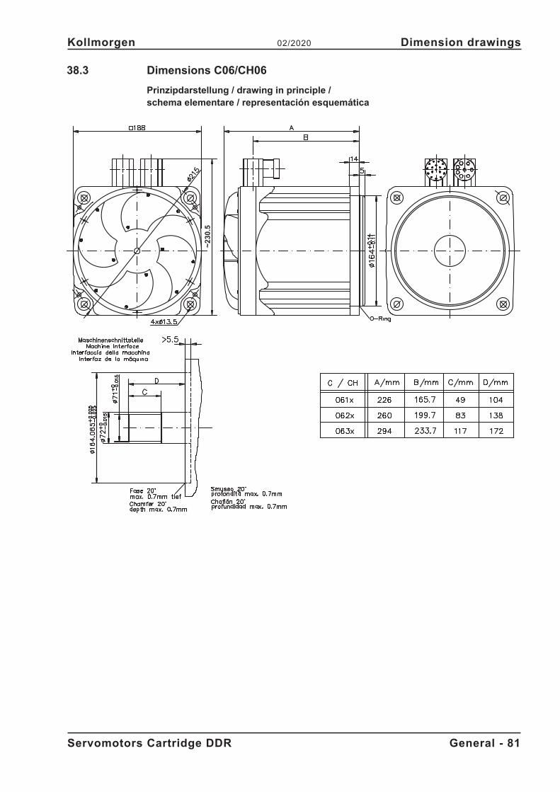
38.3 Dimensions C06/CH06
Prinzipdarstellung / drawing in principle /schema elementare / representación esquemática
Servomotors Cartridge DDR General - 81
Kollmorgen 02/2020 Dimension drawings
~2
30
.5
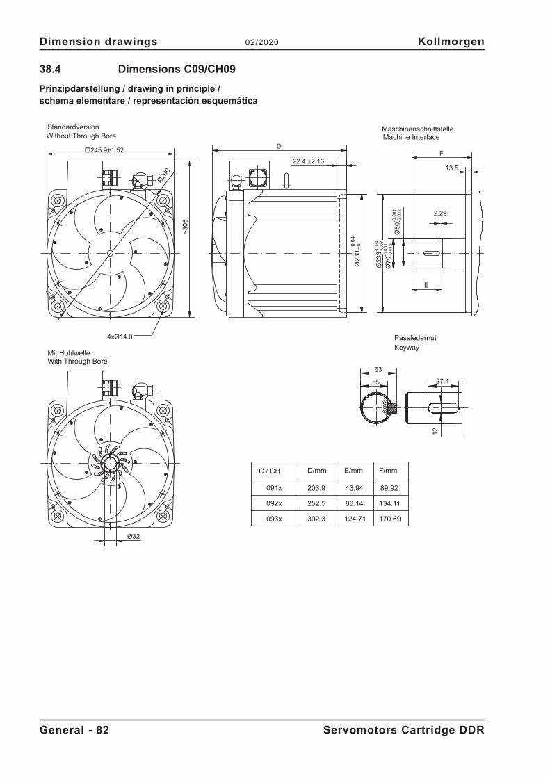
38.4 Dimensions C09/CH09
Prinzipdarstellung / drawing in principle /schema elementare / representación esquemática
General - 82 Servomotors Cartridge DDR
Dimension drawings 02/2020 Kollmorgen
Ø32
Ø70
Ø2
33
D
22.4 ±2.16F
13.5
091x
092x
093x
D/mm
203.9
252.5
302.3
E/mm
43.94
88.14
124.71
4xØ14.0
~3
06
-0.0
4-0
.08
-0.0
01
-0.0
12
-0.0
01
-0.0
12
Ø29
0
27.4
63
55
12
C / CH
MaschinenschnittstelleMachine InterfaceWithout Through Bore
Standardversion
With Through BoreMit Hohlwelle
PassfedernutKeyway
2.29
E
170.69
89.92
F/mm
Ø2
33
+0
.04
+0
Ø60
�245.9±1.52
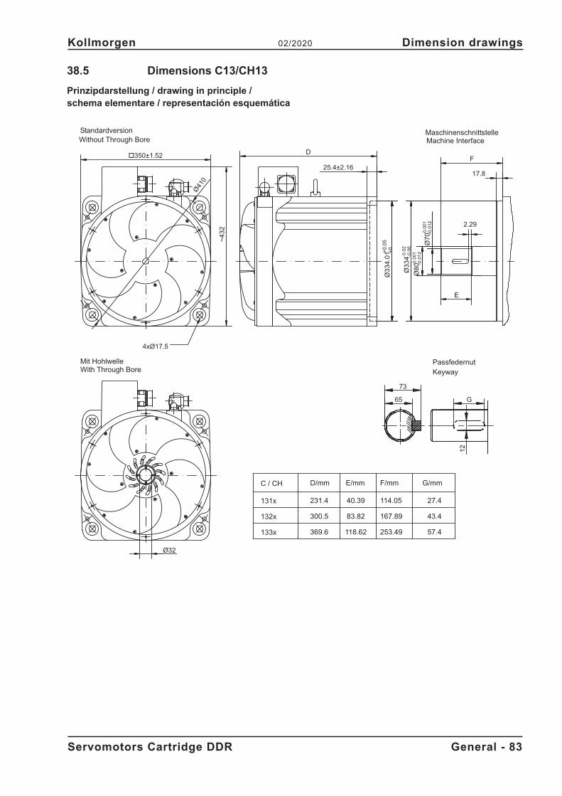
38.5 Dimensions C13/CH13
Prinzipdarstellung / drawing in principle /schema elementare / representación esquemática
Servomotors Cartridge DDR General - 83
Kollmorgen 02/2020 Dimension drawings
D
132x
131x
133x
Ø32
Standardversion
4xØ17.5
Ø41
0
~4
32
Mit HohlwelleWith Through Bore
Without Through Bore
231.4
D/mm
300.5
369.6
F/mm
167.89
253.49
Ø80-0
.00
1-0
.01
2
Ø3
34-0
.02
-0.0
6
F
Machine InterfaceMaschinenschnittstelle
-0.0
01
-0.0
12
Ø70
25.4±2.1617.8
73
Passfedernut
65 G
12
57.4
43.4
27.4
G/mmC / CH
Keyway
2.29
E
83.82
40.39
E/mm
+0
.05
+0
Ø3
34
.01
�350±1.52
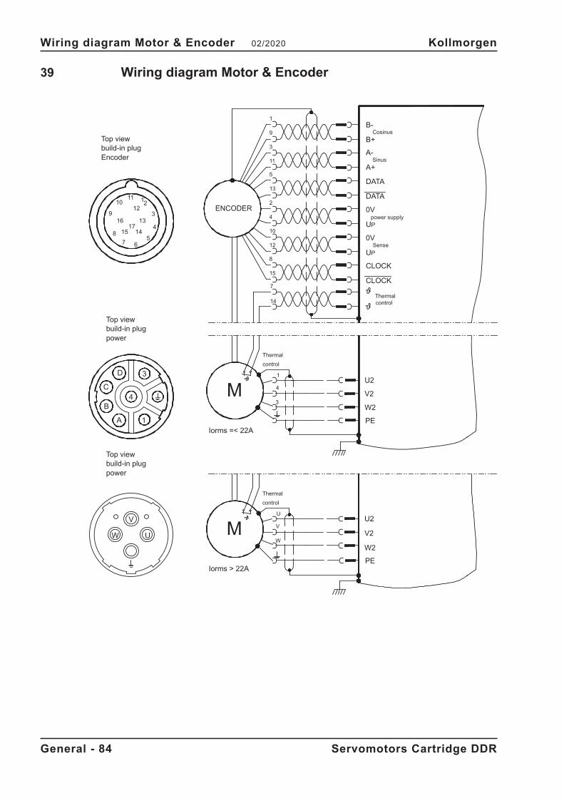
39 Wiring diagram Motor & Encoder
General - 84 Servomotors Cartridge DDR
Wiring diagram Motor & Encoder 02/2020 Kollmorgen
6
12
14
3
B
C
A
D
11
9
7
15
16
8
10
17
4
1
4 M3
4
1
15
14
7
12
8
10
1
5
13
2
4
3ENCODER
11
13
2
5
9
3
1
PE
W2
U2
V2
CLOCK
CLOCK
Sense
UP
UP
0V
Sinus
0V
A+
Cosinus
A-
B+
B-
MW
V
U
PE
W2
U2
V2
Iorms =< 22A
W U
V
Iorms > 22A
build-in plug
Thermal
build-in plugpower
control
Thermal
Thermalcontrol
power supply
control
power
Encoderbuild-in plug
40 Approvals
Declarations of Conformity can be found on the Kollmorgen website.
40.1 Conformance with UL
Recognized for USA and Canada in File E136406.
40.2 Conformance with CE
The motors have been tested by an authorized testing laboratory in a defined configura-tion. Any divergence from the configuration and installation described in this documenta-tion means that the user will be responsible for carrying out new measurements to ensureconformance with regulatory requirements.
Feedback systems and contacts must not be tested with high voltage. Feedback systemsare not suitable for high voltage testing, it is allowed to exclude sensitive electronic com-ponents from these tests. Feedback systems might be destroyed during a high voltagetest.
Kollmorgen declares the conformity of the product series Cartridge DDR with the EC LowVoltage Directive 2014/35/EC.
40.3 Conformance with RoHS
The device is manufactured in conformance with RoHS Directive 2011/65/EU with dele-gated directive 2015/863/EU for installation into a machine.
40.4 Conformance with REACH
EU Regulation no. 1907/2006 deals with the registration, evaluation, authorisation andrestriction of chemical substances 1 (abbreviated to “REACH”).
Cartridge DDR motors do not contain any substances (CMR substances, PBTsubstan-ces, vPvB substances and similar hazardous substances stipulated in individual casesbased on scientific criteria) above 0.1 mass percent per product that are included on thecandidate list.
40.5 EAC Conformance
EAC is the abbreviation for Eurasian Conformity. The mark is used in the states of theEurasian Customs Union (Russia, Belarus, Kazakhstan).
Kollmorgen declares, that the Cartridge DDR has passed all required conformity procedu-res in a member state of the Eurasian Customs Union, and that the motor meets all tech-nical requirements requested in the member states of the Eurasian Customs Union:� Low voltage (TP TC 020/2011)� EMC (TP TC 004/2011)Contact in Russia:SERVOSTAR LLC, Bld.1, Semyonovskaya nab. 2/1, RU-105094 Moskau
Servomotors Cartridge DDR General - 85
Kollmorgen 02/2020 Approvals
ServiceWir bieten Ihnen einen kompetenten und schnellenService. Wählen Sie das zuständige regionaleVertriebsbüro in Deutschland oder kontaktieren Sieden Kundenservice.
ServiceWe are committed to quality customer service. Inorder to serve in the most effective way, pleasecontact your local sales representative forassistance. If you are unaware of your local salesrepresentative, please contact us.
ServizioCi impegniamo a fornire un servizio di qualità alcliente. Per servire nel senso più efficace, pregomettasi in contatto con il vostro rappresentante localeper assistenza. Contattateci per maggioriinformazioni.
ServicioQueremos ofrecer al cliente un servicio de calidad.Para ello les agradecemos que contacten con surepresentante local de ventas. En el caso de que nolo conozcan, no duden en ponerse en contacto connosotros en las siguientes direcciones.
Europe
KOLLMORGENInternet www.kollmorgen.com/en-usSupport https://kdn.kollmorgen.com/E-Mail [email protected].: +49 (0)2102 - 9394 - 0Fax: +49 (0)2102 - 9394 - 3155
KOLLMORGEN KOLLMORGEN
EN Website Developer Network
North America
KOLLMORGENInternet www.kollmorgen.com/en-usSupport https://kdn.kollmorgen.com/E-Mail [email protected].: +1 - 540 - 633 - 3545Fax: +1 - 540 - 639 - 4162
KOLLMORGEN KOLLMORGEN
EN Website Developer Network
South America
KOLLMORGENInternet www.kollmorgen.com/pt-brSupport https://kdn.kollmorgen.com/E-Mail [email protected].: +55 11 4615 - 6300
KOLLMORGEN
Brazil Website
Asia
KOLLMORGENInternet www.kollmorgen.cnSupport https://kdn.kollmorgen.com/E-Mail [email protected]: +86 - 400 668 2802Fax: +86 - 21 6248 5367
KOLLMORGEN
CN Website