cs 1000.pdf
TRANSCRIPT
CS 1000 Series ContaminationSensor
Operating and maintenance instructions CS 1000 &Operation manual CoCoS 1000 English
Valid for firmware version V 1.28
Doc.: 3247149k / 2006-03-15

Warenzeichen Die verwendeten Warenzeichen anderer Firmen bezeichnen ausschließlich die Produkte dieser Firmen.
Trademarks The trademarks of other companies are exclusively used for the products of those companies.
Marques Les marques d’autres entreprises utilisées icise réfèrent exclusivement aux produits de ces entreprise.
Copyright © 2005 by HYDAC Filtertechnik GmbH all rights reserved Alle Rechte vorbehalten. Nachdruck oder Vervielfältigung dieses Handbuchs, auch in Teilen, in welcher Form auch immer, ist ohne ausdrückliche schriftliche Genehmigung von HYDAC Filtertechnik nicht erlaubt. Zuwiderhandlungen verpflichten zu Schadenersatz.
Copyright © 2005 by HYDAC Filtertechnik GmbH all rights reserved All rights reserved. This manual may not be reproduced in part or whole without the explicit written agreement from HYDAC Filtertechnik. Contraventions are liable to compensation.
Copyright © 2005 by HYDAC Filtertechnik GmbH all rights reserved Tous droits réservés. Toute ré-impression ou reproduktion, même partielle, de ce manuel est interdite, sous quelque forme que ce soit, sans l’autorisation écrite expresse de HYDAC Filtertechnik. Le manquement à cette condition donnera lieu à des dommages - intérêts.
Haftungsausschluss Wir haben unser Möglichstes getan, die Richtigkeit des Inhalts dieses Dokuments zu gewährleisten, dennoch können Fehler nicht ausgeschlossen werden. Deshalb übernehmen wir keine Haftung für Fehler und Mängel in diesem Dokument, auch nicht für Folgeschäden, die daraus entstehen können. Die Angaben in dieser Druckschrift werden regelmäßig überprüft, und notwendige Korrekturen sind in den nachfolgenden Auflagen enthalten. Für Anregungen und Verbesserungsvorschläge sind wir dankbar.
Technische Änderungen bleiben vorbehalten.
Inhaltliche Änderungen dieses Handbuchs behalten wir uns ohne Ankündigung vor.
Exclusion of liability We made ervery endeavour to ensure the accuracy of the contents of this document. However, errors cannot be ruled out. Consequently, we accept no liability
for such errors as may exist nor for any damage or loss whatsoever which may arise as a result of such errors.
The content of the manual is checked regularly. Any corrections required will be incorporated in subsequent editions. We welcome any suggestions for improvements.
All details are subject to technical modifications.
Exclusion de la garantie Nous avons fait tout notre possible pour garantir l'exactitude des informations contenues dans ce document .
Néanmoins, il est impossible d'exclure une erreur.Aussi n'assumons-nous aucune res-ponsabilité pour les erreurs et les déficiences de ce document, ainsi que pour les dommages consécutifs pouvant en découler.
Les informations contenues dans ce manuel sont régulièrement vérifiées et les correction nécessaires sont intégrées aux Éditions ultérieures. Veuillez nous faire de vos souhaits d'amélioration
Nous nous réservons le droit de modifier sans préavis le contenu du présent manuel.
Copyright © by HYDAC FILTERTECHNIK GmbH Industriegebiet D-66280 Sulzbach/Saar Germany Tel.: ++49 (0) 6897 / 509 – 01 Fax: ++49 (0) 6897 / 509 – 846
Copyright © by HYDAC FILTERTECHNIK GmbH Industriegebiet D-66280 Sulzbach/Saar Germany Tel.: ++49 (0) 6897 / 509 – 01 Fax: ++49 (0) 6897 / 509 – 846
Copyright © by HYDAC FILTERTECHNIK GmbH Industriegebiet D-66280 Sulzbach/Saar Germany Tel.: ++49 (0) 6897 / 509 – 01 Fax: ++49 (0) 6897 / 509 – 846
D GB F
Marcas Las marcas utilizadas de otras empresas designan exclusivamente los productos de estas empresas
Varumärken De varumärken som ägs av andra företag avser uteslutande dessa företags produkter.
Marchi di fabbrica I marchi di fabbrica di altre ditte qui utilizzati si riferiscono esclusivamente ai prodotti di queste ditte.
Copyright © 2005 by HYDAC Filtertechnik GmbH all rights reserved Reservados todos los derechos. No está permitida la reproducción total o parcial de este manual, por cualquier medio o procedimiento, sin la autorización expresa y por escrito de HYDAC Filtertechnik. Toda cF responsabilidad
Copyright © 2005 by HYDAC Filtertechnik GmbH all rights reserved Vi förbehåller oss alla rättigheter. Eftertryck eller kopiering av denna handbok i sin helhet eller delvis, i vilken form det vara må, får inte ske utan uttryckligt skriftligt tillstånd av HYDAC Filtertechnik. Överträdelse medför straffansvar.
Copyright © 2005 by HYDAC Filtertechnik GmbH all rights reserved Tutti i diritti riservati. È vietata la ristampa o riproduzione, anche parziale, in qualsiasi forma, di questo manuale senza espressa autorizzazione scritta di HYDAC Filtertechnik. Le violazioni comportano l’obbligo di risarcimento dei danni.
Exclusion de la garantie Hemos hecho todo lo posible por garantizar la exactitud del contenido de este documento. No obstante, no pueden descartarse errores. Por tanto, no nos responsabilizamos por errores u omisiones en este documento, ni por los daños que puedan derivarse de ellos. Los detalles dados en este manual se revisan regularmente, y las correcciones debidas se incluyen en las ediciones subsiguientes. Agradecemos toda sugerencia de mejora que se quiera aportar. Sujeto a modificaciones técnicas.
Todos los detalles de contenido de este manual están sujetos a modificaciones sin previo aviso.
Ansvarsfrihet Vi har gjort allt som stått i vår makt för att kunna garantera att innehållet i detta dokument är korrekt. Ändå kan vi inte utesluta att fel kan förekomma. Av detta skäl tar vi inte på vi oss något ansvar för fel och brister i dokumentet och inte heller för följdskador som kan uppkomma på grund därav. Vi går regelbundet igenom uppgifterna i denna trycksak, och erforderliga rättelser förs in i påföljande upplaga av dokumentet. Vi tar tacksamt emot förslag på förbättringar. Vi förbehåller oss rätten att ändra utrustningen i tekniskt hänseende.
Vi förbehåller oss också rätten att utan föregående meddelande göra ändringar i handbokens innehåll.
Esclusione della responsabilità Abbiamo fatto tutto il nostro possibile per garantire la correttezza del contenuto di questo documento, tuttavia non è possibile escludere errori. Perciò decliniamo ogni responsabilità per errori e carenze in questo documento ed ugualmente per i danni indiretti da essi derivanti. Il contenuto di questo manuale viene regolarmente controllato e le correzioni necessarie sono integrate nelle edizioni seguenti. Saremo grati di ogni proposta di miglioramento. Con riserva di modifiche tecniche.
Ci riserviamo il diritto di apportare senza preavviso modifiche al contenuto di questo manuale.
Copyright © by HYDAC FILTERTECHNIK GmbH Industriegebiet D-66280 Sulzbach/Saar Germany Tel.: ++49 (0) 6897 / 509 – 01 Fax: ++49 (0) 6897 / 509 – 846
Copyright © by HYDAC FILTERTECHNIK GmbH Industriegebiet D-66280 Sulzbach/Saar Germany Tel.: ++49 (0) 6897 / 509 – 01 Fax: ++49 (0) 6897 / 509 – 846
Copyright © by HYDAC FILTERTECHNIK GmbH Industriegebiet D-66280 Sulzbach/Saar Germany Tel.: ++49 (0) 6897 / 509 – 01 Fax: ++49 (0) 6897 / 509 – 846
E S I
Contents
HYDAC Filtertechnik GmbH en Page 1BeWa CS1000 3247149k en.doc 2006-02-24
Contents
1 General Safety Precautions ...................................................................................... 8
1.1 Obligations and Liability ........................................................................................ 8 1.2 Explanation of Symbols and Warnings, etc. .......................................................... 8
1.2.1 Basic Symbols .................................................................................................. 9 1.3 Proper/Designated Use ......................................................................................... 9 1.4 Improper Use......................................................................................................... 9 1.5 Safety Devices ...................................................................................................... 9 1.6 Informal Safety Precautions ................................................................................ 10 1.7 Instructions to Be Followed in the Event of an Emergency ................................. 10 1.8 Training and Instruction of Personnel.................................................................. 11 1.9 Safety Measures to Be Followed in Normal Operation ....................................... 11 1.10 Electrical Hazards ............................................................................................... 11 1.11 Maintenance, Servicing and Troubleshooting ..................................................... 12 1.12 Modifications to the CS ....................................................................................... 12 1.13 Cleaning the CS and Disposal of the Media and Agents Used ........................... 12
2 Transportation, Packing, Storage........................................................................... 13
2.1 Transportation & Packing .................................................................................... 13 2.2 Storage................................................................................................................ 13
2.2.1 Storage conditions .......................................................................................... 13 3 Model code / Product identification ....................................................................... 14
4 Scope of Delivery ..................................................................................................... 15
5 Description ............................................................................................................... 16
5.1 Restrictions Pertaining to the Use of the CS ....................................................... 16 5.2 CS1x1x Dimensions (without Display) ................................................................ 17 5.3 CS1x2x Dimensions (with Display) ..................................................................... 17 5.4 Connection Types ............................................................................................... 18
5.4.1 Pipe or Hose Connection Type (CS1xxx-x-x-x-x-0/-xxx) ................................ 18 5.4.2 Flange Connection Type (CS1xxx-x-x-x-x-1/-xxx) .......................................... 18
6 Installation ................................................................................................................ 19
6.1 Unpacking ........................................................................................................... 19 6.2 Mechanical Mounting .......................................................................................... 19
6.2.1 Display rotatable/adjustable as needed.......................................................... 20 6.3 Hydraulic Installation ........................................................................................... 21
6.3.1 Selection Guidelines for a Measurement Point............................................... 21 6.3.2 Flow Rate Q, differential pressure p∆ and viscosity ν characteristics .......... 22 6.3.3 Connect the CS to your system as follows: .................................................... 23
Contents
HYDAC Filtertechnik GmbH en Page 2BeWa CS1000 3247149k en.doc 2006-02-24
6.4 Electrical Installation............................................................................................ 24 6.4.1 Block Diagram ................................................................................................ 24 6.4.2 Connection Cable (Accessories see section 14) ............................................ 24 6.4.3 Typical Wiring Diagram................................................................................... 25
7 Description of the Measuring Modes ..................................................................... 26
7.1 Mode M1: Measure continuously ........................................................................ 26 7.2 Mode M2: Measure continuously and switch ...................................................... 26 7.3 Mode M3: Filter down to contamination level and stop ....................................... 26 7.4 Mode M4: Filter to establish contamination levels continuously.......................... 26 7.5 Mode M5: "SINGLE" measurement..................................................................... 27
8 Operation .................................................................................................................. 28
8.1 Display and Keypad Elements (CS122x only)..................................................... 28 8.1.1 Key Lock ......................................................................................................... 29
8.2 Modes and Menus............................................................................................... 30 8.2.1 Power Up Menu .............................................................................................. 30 8.2.2 Measuring Menu ............................................................................................. 31
8.3 Description of the Switching Output in the Measuring Modes............................. 35 8.3.1 Mode M1: Measure continuously.................................................................... 35
8.4 Mode M2: Measure continuously and switch ...................................................... 35 8.5 Mode M3: Filter down to contamination level and stop ....................................... 35 8.6 Mode M4: Filter to establish contamination levels continuously.......................... 35 8.7 Mode M5: Single measurement .......................................................................... 35 8.8 Switching Behavior of the Switching Output........................................................ 36
9 Analog Output (ANaOUT)...................................................................................... 37
9.1 SAE Classes ....................................................................................................... 37 9.1.1 SAE Signal Table............................................................................................ 38 9.1.2 SAE A-D (SAeMAX) ..................................................................................... 39
9.1.3 SAE Class A / B / C / D (SAE)....................................................................... 39 9.1.3.1 Time-coded signal .................................................................................... 39
9.1.3.1.1 4 – 20 mA Signal............................................................................... 40 9.1.3.1.2 0 – 10 V Signal.................................................................................. 41
9.1.4 SAE A / SAE B / SAE C / SAE D (SAE A/SAE B/SAE C/SAE D) ... 42
9.1.5 SAE + T (SAE+T)......................................................................................... 42 9.1.5.1 Time coded Signal .................................................................................... 43
9.1.5.1.1 4 – 20 mA Signal............................................................................... 43 9.1.5.1.2 0 – 10 V Signal.................................................................................. 44
9.2 ISO Classes ........................................................................................................ 45 9.2.1 ISO Signal Table............................................................................................. 45 9.2.2 ISO 4 / ISO 6 / ISO 14 (ISO 4 / ISO 6 / ISO 14) ....................... 46
Contents
HYDAC Filtertechnik GmbH en Page 3BeWa CS1000 3247149k en.doc 2006-02-24
9.2.3 ISO Code (ISO), 3-digit ................................................................................ 46 9.2.3.1 Time-coded Signal.................................................................................... 46
9.2.3.1.1 4 – 20 mA Signal............................................................................... 47 9.2.3.1.2 0 – 10 V Signal.................................................................................. 48
9.2.4 ISO + T (ISO+T).......................................................................................... 48 9.2.4.1 Time-coded Signal.................................................................................... 48
9.2.4.1.1 4 – 20 mA Signal............................................................................... 49 9.2.4.1.2 0 – 10 V Signal.................................................................................. 50
9.2.5 Fluid Temperature (TEMP)............................................................................ 51 9.2.5.1 Temperature table .................................................................................... 51
10 RS-485 Interface ....................................................................................................... 53
11 Condition Sensor Interface (CSI-D-5)..................................................................... 54
11.1 Scope of delivery: ................................................................................................ 54 11.2 CSI-D-5 Connection schematic ........................................................................... 54 11.3 Power adaptor set-up .......................................................................................... 55
12 Contamination Control Software 1000 (CoCoS 1000)........................................... 56
12.1 General Remarks ................................................................................................ 56 12.2 System Requirements ......................................................................................... 56 12.3 Adaptor Box — Driver Installation ....................................................................... 56 12.4 Installing CoCoS 1000......................................................................................... 58 12.5 Using CoCoS 1000.............................................................................................. 61 12.6 Save Results online............................................................................................. 64 12.7 Troubleshooting................................................................................................... 65
13 Removing the CS from the Hydraulic System....................................................... 66
13.1 Disposal / Recycling and Decommissioning........................................................ 66 14 Spare parts and Accessories.................................................................................. 66
15 ISO 4406 and SAE AS 4059 Classes....................................................................... 67
15.1 ISO 4406:1999 .................................................................................................... 67 15.1.1 ISO 4406 table................................................................................................ 67
15.2 SAE AS 4059 ...................................................................................................... 68 15.2.1 SAE AS 4059 table ......................................................................................... 68
16 Status LED - Display / Error codes......................................................................... 69
17 Factory default settings / Basic settings ............................................................... 71
17.1 Power Up menu................................................................................................... 71 17.2 Measuring menu.................................................................................................. 71
18 Technical data .......................................................................................................... 72
19 Service ...................................................................................................................... 73
20 Model code ............................................................................................................... 74
Contents
HYDAC Filtertechnik GmbH en Page 4BeWa CS1000 3247149k en.doc 2006-02-24
Foreword
HYDAC Filtertechnik GmbH en Page 5en Vorwort.doc 2006-01-06
Foreword For you,
as owner of a product manufactured by us, we have produced this manual, comprising the most important instructions for its operation and maintenance.
It is intended to help you become acquainted with the proper/designated use of the product and use it properly. You should keep it in the vicinity of the product so it is always at your fingertips.
Sometimes the information contained in this documentation cannot always keep up with changes made to the product as we attach considerable importance to keeping our products cutting-edge. Consequently, there might be deviations in technical details, illustrations and dimensions.
In these cases we go to every effort to keep your documentation current by sending you updates.
But we need your help. Please make sure that you incorporate the updates in your documentation and that non-current sections are removed.
If you discover errors while reading the documentation or have suggestions or other useful information, please don’t hesitate to contact us:
HYDAC Filtertechnik GmbH Dept.: SFVI, Techn. Documentation P. O. Box 1251 66273 Sulzbach / Saar, Germany
Fax: ++49 (0) 6897 509 846 Email: [email protected]
The editor would welcome your involvement.
“Putting experience into practice”
Foreword
HYDAC Filtertechnik GmbH en Page 6en Vorwort.doc 2006-01-06
Customer Service If you have any questions, suggestions, or encounter any problems of a technical nature, please contact: When contacting us, please always include the model/type designation and article no. / serial no. / firmware version of the product:
Fax: ++49 (0) 6897 509 846 Email: [email protected]
Modifications to the Product We would like to point out that changes to the product (e.g. purchasing options, etc.) may result in the information in the operating instructions no longer being completely accurate or sufficient.
When making modifications or performing repair work to components affecting the safety of the product, the product may not be put back into operation until it has been examined and released by a HYDAC representative.
Please notify us immediately of any modifications made to the product whether by you or a third party.
Warranty For the warranty provided by us, please refer to the General Conditions of Sale and Delivery of HYDAC Filtertechnik GmbH.
They are available at: www.hydac.com E-Business Legal information.
Foreword
HYDAC Filtertechnik GmbH en Page 7en Vorwort.doc 2006-01-06
... And now for a few tips on using this documentation.
The following example shows you how you can access the information you are looking for quick and easy.
WHAT do I want to know?
WHERE can I find the information I’m looking for?
The documentation is subdivided into chapters and sections.
1. Look for the table of contents.
2. Skim the boldfaced section headings.
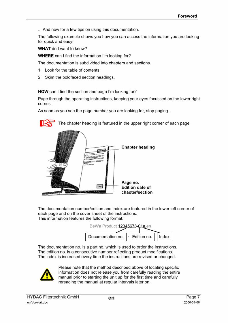
HOW can I find the section and page I’m looking for?
Page through the operating instructions, keeping your eyes focussed on the lower right corner.
As soon as you see the page number you are looking for, stop paging.
The chapter heading is featured in the upper right corner of each page.
The documentation number/edition and index are featured in the lower left corner of each page and on the cover sheet of the instructions. This information features the following format:
The documentation no. is a part no. which is used to order the instructions. The edition no. is a consecutive number reflecting product modifications. The index is increased every time the instructions are revised or changed.
Please note that the method described above of locating specific information does not release you from carefully reading the entire manual prior to starting the unit up for the first time and carefully rereading the manual at regular intervals later on.
Chapter heading
Page no. Edition date of chapter/section
Documentation no. Edition no. Index -
BeWa Product 12345678-01a en
ContaminationSensor CS General Safety Precautions
HYDAC Filtertechnik GmbH en Page 8BeWa CS1000 3247149k en.doc 2004-07-12
1 General Safety Precautions These operating instructions contain the key instructions for properly and safely operating the CS.
1.1 Obligations and Liability • The basic prerequisite for the safe and proper handling and operation of the CS is
knowledge of the safety instructions and warnings.
• These operating instructions in general, and the safety precautions in particular, are to be adhered by all those who work with the CS.
• Adherence is to be maintained to pertinent accident prevention regulations applicable at the site where the product is used.
• The safety precautions listed herein are limited solely to using the CS.
The CS has been designed and constructed in accordance with the current state of the art and recognized safety regulations. Nevertheless, hazards may be posed to the life and limb of the individual using the product or to third parties. Risk of damage may be posed to the product or other equipment and property. The CS is to be used as follows:
• solely for its designated use
• only when in a safe, perfect condition
• Any faults or malfunctions which might impair safety are to be properly repaired or remedied immediately.
Our General Terms and Conditions apply. They are made available to the owner upon concluding purchase of the product at the latest. Any and all warranty and liability claims for personal injuries and damage to property shall be excluded in the event they are attributable to one or more of the following causes:
• improper use of the CS or use deviating from its designated use
• improper assembly, installation, commissioning, operation and maintenance of the CS
• operating the CS when the system equipment or systems are defective
• modifications to the product made by the user or purchaser
• improper monitoring of product components subject to wear and tear
• improperly performed repair work
1.2 Explanation of Symbols and Warnings, etc. The following designations and symbols are used in this manual to designate hazards, etc.:
ContaminationSensor CS General Safety Precautions
HYDAC Filtertechnik GmbH en Page 9BeWa CS1000 3247149k en.doc 2004-07-12
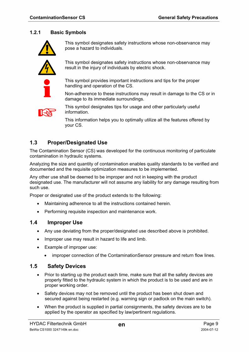
1.2.1 Basic Symbols
This symbol designates safety instructions whose non-observance may pose a hazard to individuals.
This symbol designates safety instructions whose non-observance may result in the injury of individuals by electric shock.
This symbol provides important instructions and tips for the proper handling and operation of the CS.
Non-adherence to these instructions may result in damage to the CS or in damage to its immediate surroundings.
This symbol designates tips for usage and other particularly useful information.
This information helps you to optimally utilize all the features offered by your CS.
1.3 Proper/Designated Use The Contamination Sensor (CS) was developed for the continuous monitoring of particulate contamination in hydraulic systems.
Analyzing the size and quantity of contamination enables quality standards to be verified and documented and the requisite optimization measures to be implemented.
Any other use shall be deemed to be improper and not in keeping with the product designated use. The manufacturer will not assume any liability for any damage resulting from such use.
Proper or designated use of the product extends to the following:
• Maintaining adherence to all the instructions contained herein.
• Performing requisite inspection and maintenance work.
1.4 Improper Use • Any use deviating from the proper/designated use described above is prohibited.
• Improper use may result in hazard to life and limb.
• Example of improper use:
• improper connection of the ContaminationSensor pressure and return flow lines.
1.5 Safety Devices • Prior to starting up the product each time, make sure that all the safety devices are
properly fitted to the hydraulic system in which the product is to be used and are in proper working order.
• Safety devices may not be removed until the product has been shut down and secured against being restarted (e.g. warning sign or padlock on the main switch).
• When the product is supplied in partial consignments, the safety devices are to be applied by the operator as specified by law/pertinent regulations.
ContaminationSensor CS General Safety Precautions
HYDAC Filtertechnik GmbH en Page 10BeWa CS1000 3247149k en.doc 2004-07-12
1.6 Informal Safety Precautions • Make sure to always keep the operating instructions in the vicinity of the product.
• Apart from the operating instructions, any and all general and local regulations pertaining to accident prevention and environmental protection are to be made available and observance to be maintained to them.
• Make sure to keep the safety and hazard symbols and warnings on the product in a legible condition.
• The power plug/cord of the product is to always be pulled before opening any components of the product. Tests conducted with the housing open may only be performed by properly trained, certified electricians. This also applies to all repair work or to any modifications to electric components approved by us.
• The hoses and connection fittings are to be checked daily for leakage (visual check). The electrical components of the product are to also be regularly checked (visual check once a month). Any loose connections or damaged cables are to be replaced immediately.
Warning: Pressurized fluids pose a hazard to life and limb. Consequently, the safety regulations pertaining to working with pressurized liquids are to be adhered to at all time!
1.7 Instructions to Be Followed in the Event of an Emergency
In the event of an emergency, immediately disconnect the CS from the power supply and from the hydraulic system! Properly dispose of any exiting fluid in accordance with environmental guidelines.
ContaminationSensor CS General Safety Precautions
HYDAC Filtertechnik GmbH en Page 11BeWa CS1000 3247149k en.doc 2004-07-12
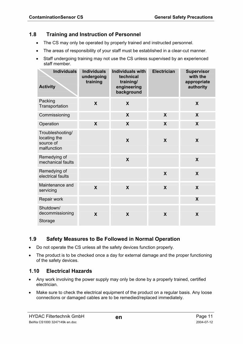
1.8 Training and Instruction of Personnel • The CS may only be operated by properly trained and instructed personnel.
• The areas of responsibility of your staff must be established in a clear-cut manner.
• Staff undergoing training may not use the CS unless supervised by an experienced staff member.
Individuals Activity
Individuals undergoing
training
Individuals with technical training/
engineering background
Electrician Supervisor with the
appropriate authority
Packing Transportation X X X
Commissioning X X X
Operation X X X X
Troubleshooting/ locating the source of malfunction
X X X
Remedying of mechanical faults X X
Remedying of electrical faults X X
Maintenance and servicing X X X X
Repair work X
Shutdown/ decommissioning
Storage X X X X
1.9 Safety Measures to Be Followed in Normal Operation • Do not operate the CS unless all the safety devices function properly.
• The product is to be checked once a day for external damage and the proper functioning of the safety devices.
1.10 Electrical Hazards • Any work involving the power supply may only be done by a properly trained, certified
electrician.
• Make sure to check the electrical equipment of the product on a regular basis. Any loose connections or damaged cables are to be remedied/replaced immediately.
ContaminationSensor CS General Safety Precautions
HYDAC Filtertechnik GmbH en Page 12BeWa CS1000 3247149k en.doc 2004-07-12
• If work to live components is required, a second individual is required who can switch off the product at the main switch as may prove necessary.
1.11 Maintenance, Servicing and Troubleshooting • The prescribed adjustment, maintenance/servicing and inspection work is to be
conducted in a timely fashion.
• All operating media is to be protected/isolated for the event that the product is accidentally started up.
• The CS is to be disconnected from the power supply and protected against being inadvertently switched back on when performing any maintenance, servicing, inspection or repair work.
• Any screwed fittings which have been undone/removed are to be checked to see that they have been properly resecured.
• Always check the product to see that it functions properly when performing maintenance and servicing work.
1.12 Modifications to the CS • Do not make any modifications (design modifications, extensions) to the CS without the
prior consent of the manufacturer.
• Any design modifications or extensions may not be made without HYDAC Filtertechnik GmbH’s express prior written approval.
• Immediately replace any machine components which are not in perfect condition.
• Only use original (OEM) spare parts and consumables. When using non-OEM components it cannot be ensured that they have been designed and manufactured so as to comply with loading and safety requirements.
1.13 Cleaning the CS and Disposal of the Media and Agents Used • The cleaning agents and flushing oils used are to be handled and disposed of properly.
• To this end, the manufacturer’s instructions pertaining to possible use, wearing of protective clothing and gear, and proper disposal are to be adhered to.
Some cleaning agents may pose a health hazard, especially when undiluted.
Packing, Transportation, Storage
HYDAC Filtertechnik GmbH en Page 13BeWa CS1000 3247149k en.doc 2006-02-24
2 Transportation, Packing, Storage
2.1 Transportation & Packing • The CS comes wrapped/packed in a cardboard box.
• When receiving and unpacking the unit check it for damage in transit. Report any damage to the forwarding agent immediately.
2.2 Storage • Make sure to store the CS in a clean, dry place, in the original packing, if possible. Do not
remove the packing until you are ready to install the unit.
• If the CS is to be put into storage for an extended period of time, it should be completely drained (if necessary, it should be flushed, using n-heptane) so as to prevent it from gumming up.
• Any cleaning agents and flushing oils used are to be handled and disposed of properly.
2.2.1 Storage conditions Storage temperature: -40°C ... +80°C / -40°F ... + 176°F
Relative humidity: max. 95%, non-condensing
Model code / Product identification
HYDAC Filtertechnik GmbH en Page 14BeWa CS1000 3247149k en.doc 2006-03-14
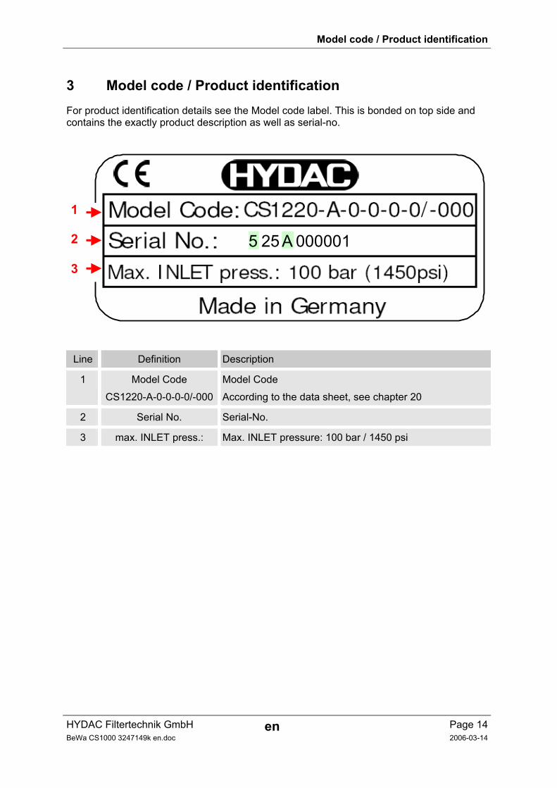
3 Model code / Product identification For product identification details see the Model code label. This is bonded on top side and contains the exactly product description as well as serial-no.
5 00000125 A
1
2
3
Line Definition Description
1 Model Code
CS1220-A-0-0-0-0/-000
Model Code
According to the data sheet, see chapter 20
2 Serial No. Serial-No.
3 max. INLET press.: Max. INLET pressure: 100 bar / 1450 psi
Scope of Delivery
HYDAC Filtertechnik GmbH en Page 15BeWa CS1000 3247149k en.doc 2006-02-24
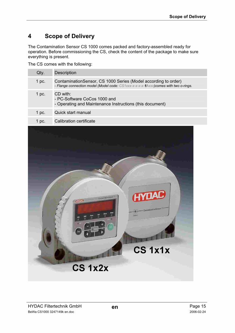
4 Scope of Delivery The Contamination Sensor CS 1000 comes packed and factory-assembled ready for operation. Before commissioning the CS, check the content of the package to make sure everything is present.
The CS comes with the following:
Qty. Description
1 pc. ContaminationSensor, CS 1000 Series (Model according to order) - Flange connection model (Model code: CS1xxx-x-x-x-x-1/-xxx)comes with two o-rings.
1 pc. CD with: - PC-Software CoCos 1000 and - Operating and Maintenance Instructions (this document)
1 pc. Quick start manual
1 pc. Calibration certificate
Installation and Operation
HYDAC Filtertechnik GmbH en Page 16BeWa CS1000 3247149k en.doc 2006-03-14
5 Description The CS 1000 Series Contamination Sensor is a stationary measurement unit for the continuous monitoring of particulate contamination in hydraulic and lubrication systems.
The CS is designed for connection to low- or high-pressure hydraulic and lubrication lines and testbenches from which a small flow of oil (between 30 ml/min and 300 ml/min) is diverted for measurement purposes. The contamination sensor is suitable for pressure ranges up to 100 bar and viscosities up to 1000 mm²/s.
Particulate contamination is detected using an optical measurement cell.
Measurement results can be output as contamination code according to ISO 4406 : 1999 or SAE AS 4059 (D) (cleanliness classes: >4 µm( c) >6 µm( c) >14 µm( c)>21 µm( c)).
The sensor is available with the following options: • with or without 6-digit display and keypad (the display can be rotated by 270°) — see
section 6.2.1 ) • with a 4 – 20 mA or 0 – 10 V analog output • pipe / hose mounting or flange mounting (see section 5.4.1 or 5.4.2)
All models feature an analog electric output and an RS485 interface for outputting the measured contamination levels. Additionally, an electronic switching output can be configured to alert the operator about rising or falling contamination levels.
5.1 Restrictions Pertaining to the Use of the CS
The CS 1xx0 is qualified for mineral oils (or mineral-oil-based raffinates). The CS 1xx1 is qualified for phosphate esters.
Please contact us first before using the unit with other fluids.
Installation and Operation
HYDAC Filtertechnik GmbH en Page 17BeWa CS1000 3247149k en.doc 2006-03-14
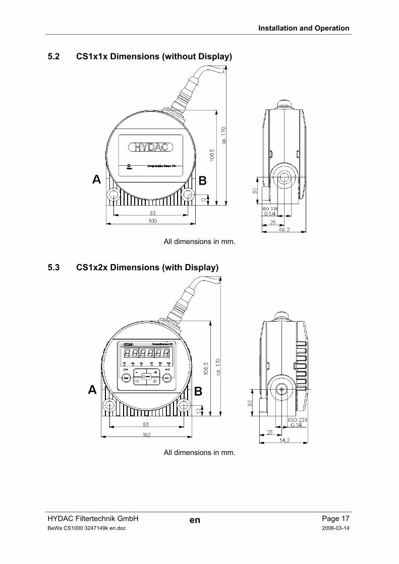
5.2 CS1x1x Dimensions (without Display)
All dimensions in mm.
5.3 CS1x2x Dimensions (with Display)
All dimensions in mm.
Installation and Operation
HYDAC Filtertechnik GmbH en Page 18BeWa CS1000 3247149k en.doc 2006-03-14
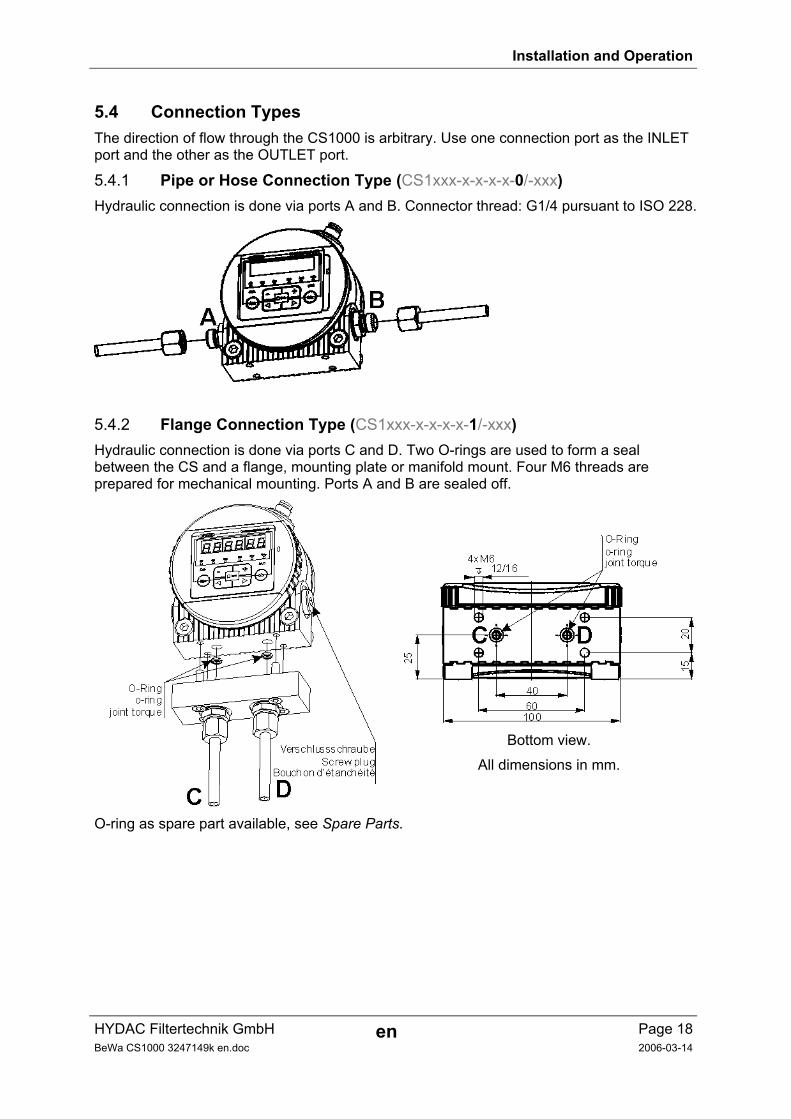
5.4 Connection Types The direction of flow through the CS1000 is arbitrary. Use one connection port as the INLET port and the other as the OUTLET port.
5.4.1 Pipe or Hose Connection Type (CS1xxx-x-x-x-x-0/-xxx) Hydraulic connection is done via ports A and B. Connector thread: G1/4 pursuant to ISO 228.
5.4.2 Flange Connection Type (CS1xxx-x-x-x-x-1/-xxx) Hydraulic connection is done via ports C and D. Two O-rings are used to form a seal between the CS and a flange, mounting plate or manifold mount. Four M6 threads are prepared for mechanical mounting. Ports A and B are sealed off.
Bottom view.
All dimensions in mm.
O-ring as spare part available, see Spare Parts.
Installation and Operation
HYDAC Filtertechnik GmbH en Page 19BeWa CS1000 3247149k en.doc 2006-03-14
6 Installation For operation the CS must be hydraulically (see section 6.3) and electrically (see section 6.4) installed.
6.1 Unpacking The CS comes packed in a cardboard box.
Unpack the unit and check it for damage in transit. Report any damage to the forwarding agent immediately. Check for scope of delivery, see section 4.
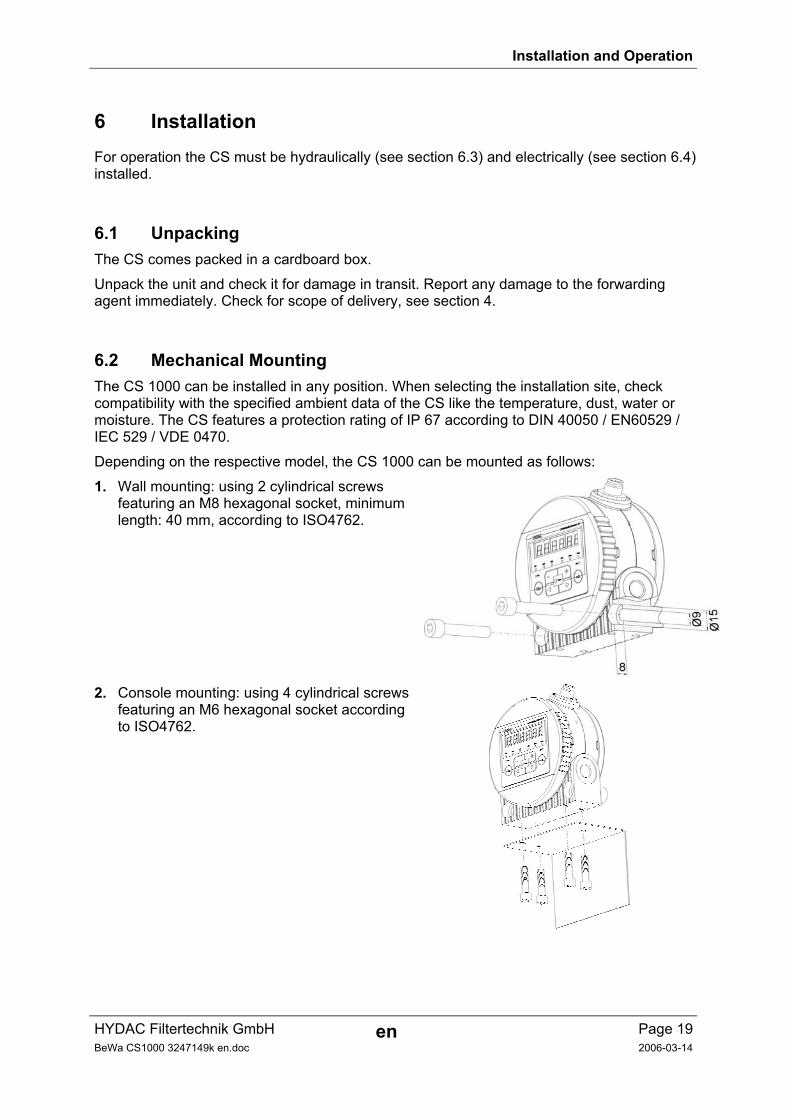
6.2 Mechanical Mounting The CS 1000 can be installed in any position. When selecting the installation site, check compatibility with the specified ambient data of the CS like the temperature, dust, water or moisture. The CS features a protection rating of IP 67 according to DIN 40050 / EN60529 / IEC 529 / VDE 0470.
Depending on the respective model, the CS 1000 can be mounted as follows:
1. Wall mounting: using 2 cylindrical screws featuring an M8 hexagonal socket, minimum length: 40 mm, according to ISO4762.
2. Console mounting: using 4 cylindrical screws featuring an M6 hexagonal socket according to ISO4762.
Installation and Operation
HYDAC Filtertechnik GmbH en Page 20BeWa CS1000 3247149k en.doc 2006-03-14
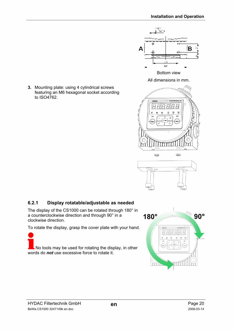
Bottom view
All dimensions in mm.
3. Mounting plate: using 4 cylindrical screws featuring an M6 hexagonal socket according to ISO4762.
6.2.1 Display rotatable/adjustable as needed The display of the CS1000 can be rotated through 180° in a counterclockwise direction and through 90° in a clockwise direction.
To rotate the display, grasp the cover plate with your hand.
No tools may be used for rotating the display, in other words do not use excessive force to rotate it.
Installation and Operation
HYDAC Filtertechnik GmbH en Page 21BeWa CS1000 3247149k en.doc 2006-03-14
6.3 Hydraulic Installation The direction of flow through the CS1000 is arbitrary. Use one connection port as the INLET port and the other as the OUTLET port.
Depending on how the CS is ordered, it features the following hydraulic connection options:
- Pipe/hose connection: The CS is connected to the hydraulic system via ports A and B using a pipe or hose. (see section 5.2)
- Flange connection: The CS is screwed to a flange, mounting plate, manifold mount or control block, with flow being effected through the unit via port C and D on the underside.
Determine the system pressure of the hydraulic system and see whether it is within the
permissible range for the INLET port.
The pressure in the measurement cell may not exceed 100 bar.
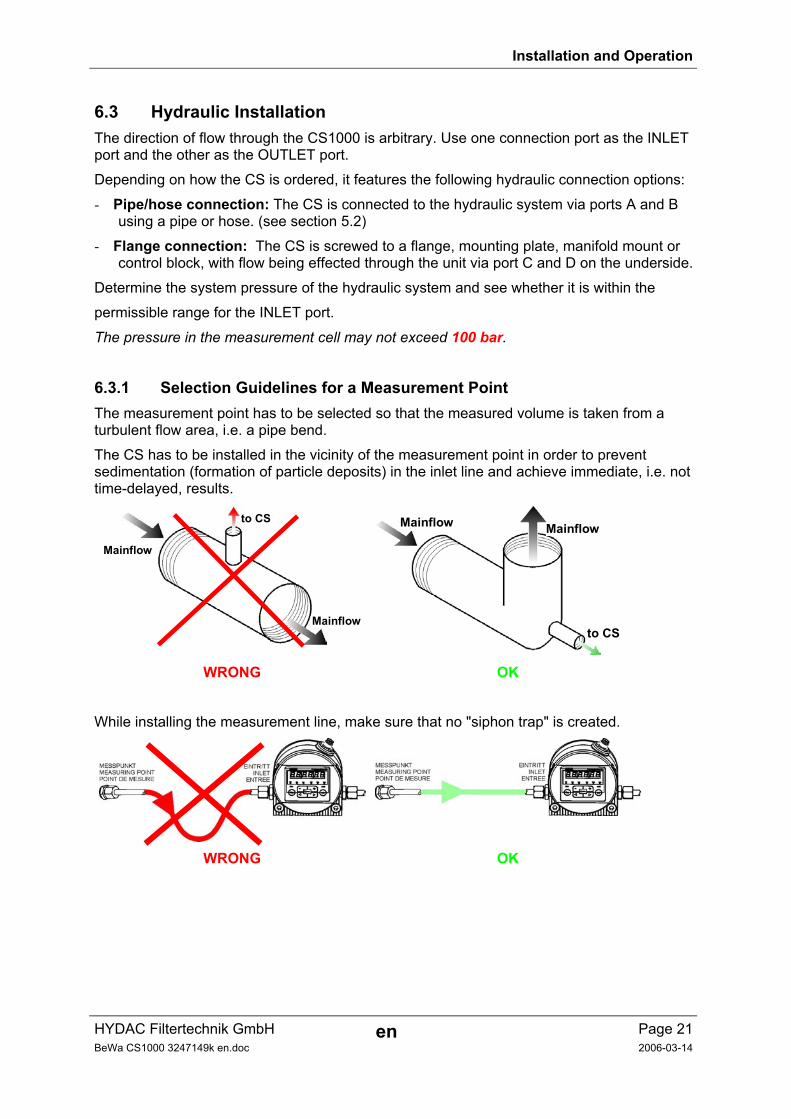
6.3.1 Selection Guidelines for a Measurement Point The measurement point has to be selected so that the measured volume is taken from a turbulent flow area, i.e. a pipe bend.
The CS has to be installed in the vicinity of the measurement point in order to prevent sedimentation (formation of particle deposits) in the inlet line and achieve immediate, i.e. not time-delayed, results.
Mainflow
Mainflow
to CS Mainflow Mainflow
to CS
WRONG OK
While installing the measurement line, make sure that no "siphon trap" is created.
WRONG OK
Installation and Operation
HYDAC Filtertechnik GmbH en Page 22BeWa CS1000 3247149k en.doc 2006-03-14
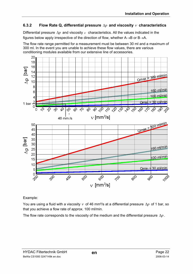
6.3.2 Flow Rate Q, differential pressure p∆ and viscosity ν characteristics
Differential pressure p∆ and viscosity ν characteristics. All the values indicated in the figures below apply irrespective of the direction of flow, whether A→B or B→A.
The flow rate range permitted for a measurement must be between 30 ml and a maximum of 300 ml. In the event you are unable to achieve these flow values, there are various conditioning modules available from our extensive line of accessories.
Example:
You are using a fluid with a viscosity ν of 46 mm²/s at a differential pressure p∆ of 1 bar, so that you achieve a flow rate of approx. 100 ml/min.
The flow rate corresponds to the viscosity of the medium and the differential pressure p∆ .
Installation and Operation
HYDAC Filtertechnik GmbH en Page 23BeWa CS1000 3247149k en.doc 2006-03-14
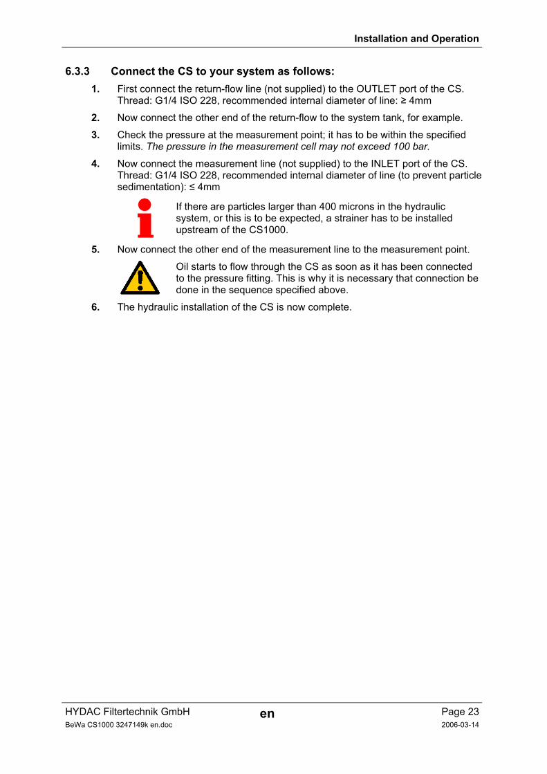
6.3.3 Connect the CS to your system as follows: 1. First connect the return-flow line (not supplied) to the OUTLET port of the CS.
Thread: G1/4 ISO 228, recommended internal diameter of line: ≥ 4mm
2. Now connect the other end of the return-flow to the system tank, for example.
3. Check the pressure at the measurement point; it has to be within the specified limits. The pressure in the measurement cell may not exceed 100 bar.
4. Now connect the measurement line (not supplied) to the INLET port of the CS. Thread: G1/4 ISO 228, recommended internal diameter of line (to prevent particle sedimentation): ≤ 4mm
If there are particles larger than 400 microns in the hydraulic system, or this is to be expected, a strainer has to be installed upstream of the CS1000.
5. Now connect the other end of the measurement line to the measurement point.
Oil starts to flow through the CS as soon as it has been connected to the pressure fitting. This is why it is necessary that connection be done in the sequence specified above.
6. The hydraulic installation of the CS is now complete.
Installation and Operation
HYDAC Filtertechnik GmbH en Page 24BeWa CS1000 3247149k en.doc 2006-03-14
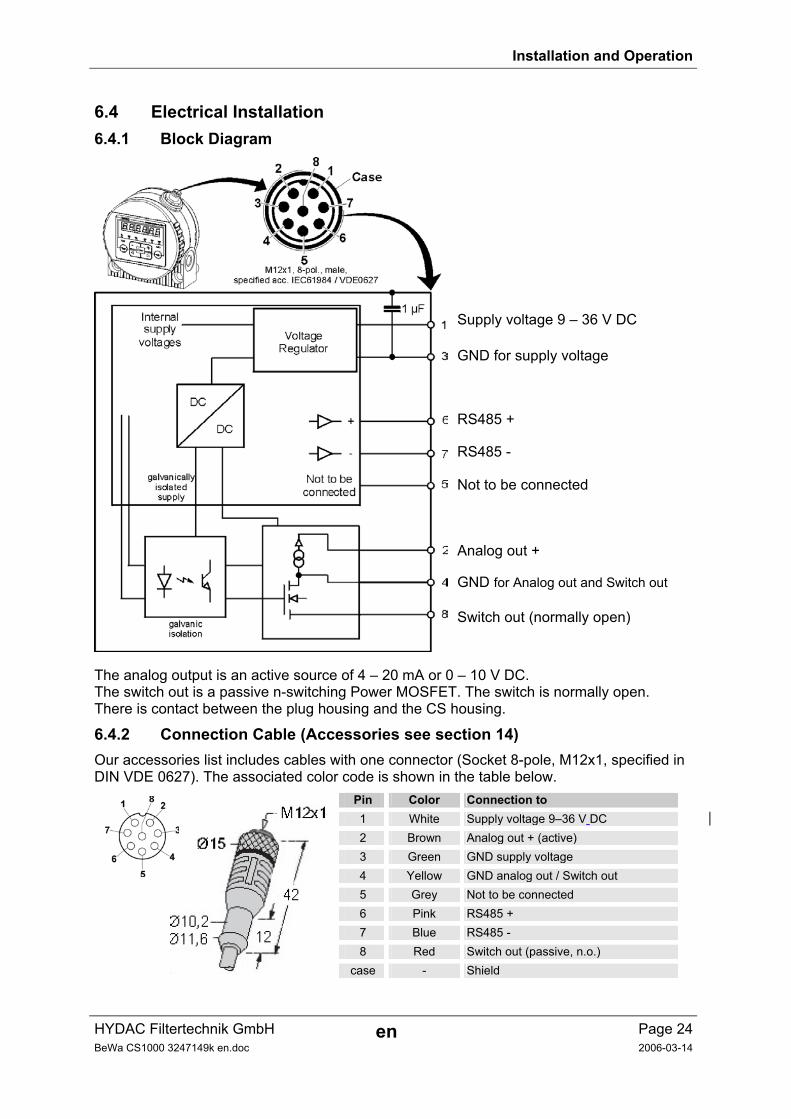
6.4 Electrical Installation 6.4.1 Block Diagram
Supply voltage 9 – 36 V DC
GND for supply voltage
RS485 +
RS485 -
Not to be connected
Analog out +
GND for Analog out and Switch out
Switch out (normally open)
The analog output is an active source of 4 – 20 mA or 0 – 10 V DC. The switch out is a passive n-switching Power MOSFET. The switch is normally open. There is contact between the plug housing and the CS housing.
6.4.2 Connection Cable (Accessories see section 14) Our accessories list includes cables with one connector (Socket 8-pole, M12x1, specified in DIN VDE 0627). The associated color code is shown in the table below.
Pin Color Connection to 1 White Supply voltage 9–36 V DC 2 Brown Analog out + (active) 3 Green GND supply voltage 4 Yellow GND analog out / Switch out 5 Grey Not to be connected 6 Pink RS485 + 7 Blue RS485 - 8 Red Switch out (passive, n.o.)
case - Shield
Installation and Operation
HYDAC Filtertechnik GmbH en Page 25BeWa CS1000 3247149k en.doc 2006-03-14
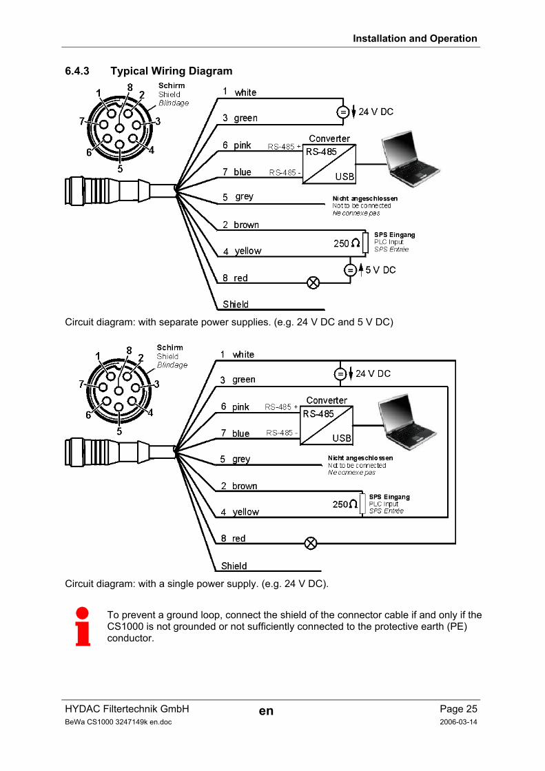
6.4.3 Typical Wiring Diagram
Circuit diagram: with separate power supplies. (e.g. 24 V DC and 5 V DC)
Circuit diagram: with a single power supply. (e.g. 24 V DC).
To prevent a ground loop, connect the shield of the connector cable if and only if the CS1000 is not grounded or not sufficiently connected to the protective earth (PE) conductor.
Installation and Operation
HYDAC Filtertechnik GmbH en Page 26BeWa CS1000 3247149k en.doc 2006-03-14
7 Description of the Measuring Modes After powering up, the CS 1000 automatically runs in one of the following measuring modes (set in Power Up Mode).
7.1 Mode M1: Measure continuously Application: Stand-alone sensor
Active data outputs: Display & RS485 & analog output
Purpose: Pure measurement only
Function: Continuous measurement of solid contamination, without any switching functions
7.2 Mode M2: Measure continuously and switch Application: Stand-alone sensor with monitoring of alerts
Active data outputs: Display & RS485 & analog output & switching output
Purpose: Continuous measurement and drive of signal lamps etc.
Function: Continuous measurement of solid contamination, continuous monitoring of programmable threshold, if threshold is exceeded, the switching output is activated to monitor an alert on site
7.3 Mode M3: Filter down to contamination level and stop Application: Control of Filter cart
Active data outputs: Display & RS485 & analog output & switching output
Purpose: Clean-up of a hydraulic reservoir
Function: Control of a filter unit, continuous measurement of solid contamination, if pre-programmed cleanliness level is reached 5 times in sequence, the pump is stopped
7.4 Mode M4: Filter to establish contamination levels continuously Application: Control of stationary offline filtration unit
Active data outputs: Display & RS485 & analog output & switching output
Purpose: Establish reservoir cleanliness between min/max levels
Function: Control of a filter unit, continuous measurement of solid contamination, if pre-programmed min/max levels are exceeded, the pump is switched on/off to keep cleanliness within range
Installation and Operation
HYDAC Filtertechnik GmbH en Page 27BeWa CS1000 3247149k en.doc 2006-03-14
7.5 Mode M5: "SINGLE" measurement Application: Stand-alone sensor
Active data outputs: Display & RS485 & analog output
Purpose: Perform a single measurement only
Function: Single measurement of solid contamination, without any switching functions
Installation and Operation
HYDAC Filtertechnik GmbH en Page 28BeWa CS1000 3247149k en.doc 2006-03-14
8 Operation After the CS 1000 is switched on "HYDAC CS 1000" appears in the display in moving letters, followed by the firmware version being displayed for 2 seconds.
This is followed by a countdown: WAIT99 -> WAIT0. The duration of the countdown is in relation to the measuring time value set. The countdown from 99 – 0 runs within the measuring time set (factory setting = 60 sec).
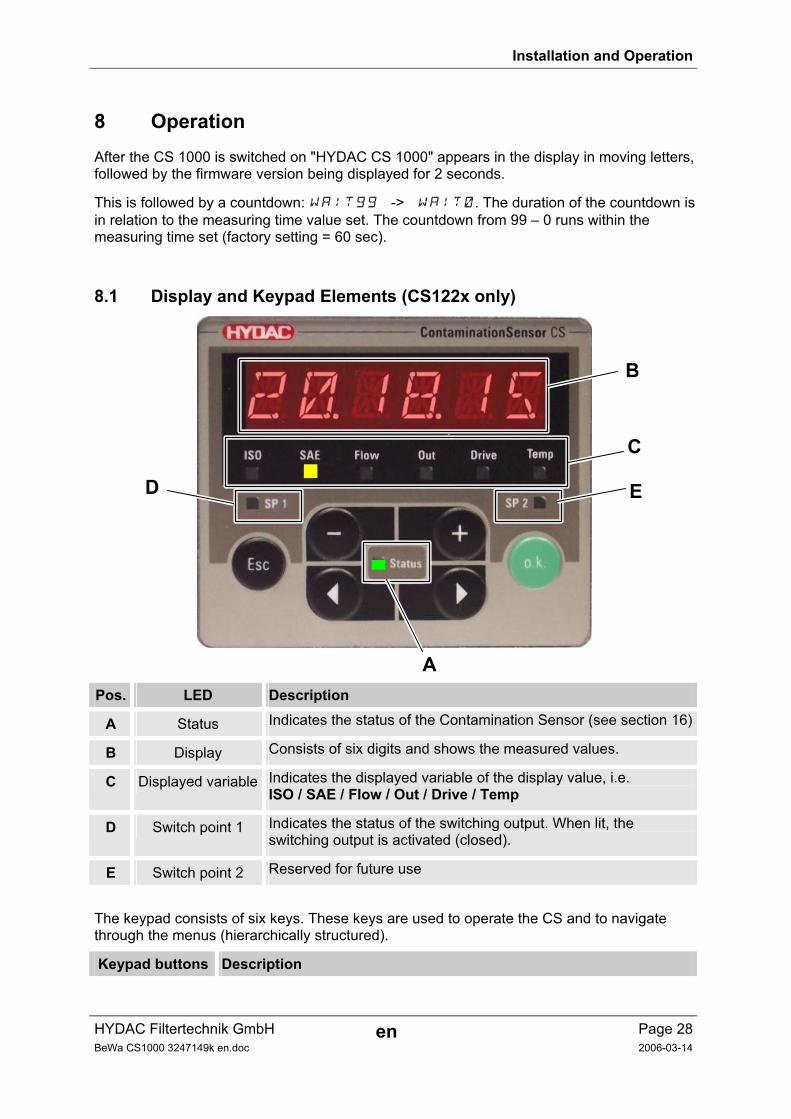
8.1 Display and Keypad Elements (CS122x only)
B
C
ED
A Pos. LED Description
A Status Indicates the status of the Contamination Sensor (see section 16)
B Display Consists of six digits and shows the measured values.
C Displayed variable Indicates the displayed variable of the display value, i.e. ISO / SAE / Flow / Out / Drive / Temp
D Switch point 1 Indicates the status of the switching output. When lit, the switching output is activated (closed).
E Switch point 2 Reserved for future use
The keypad consists of six keys. These keys are used to operate the CS and to navigate through the menus (hierarchically structured).
Keypad buttons Description
Installation and Operation
HYDAC Filtertechnik GmbH en Page 29BeWa CS1000 3247149k en.doc 2006-03-14
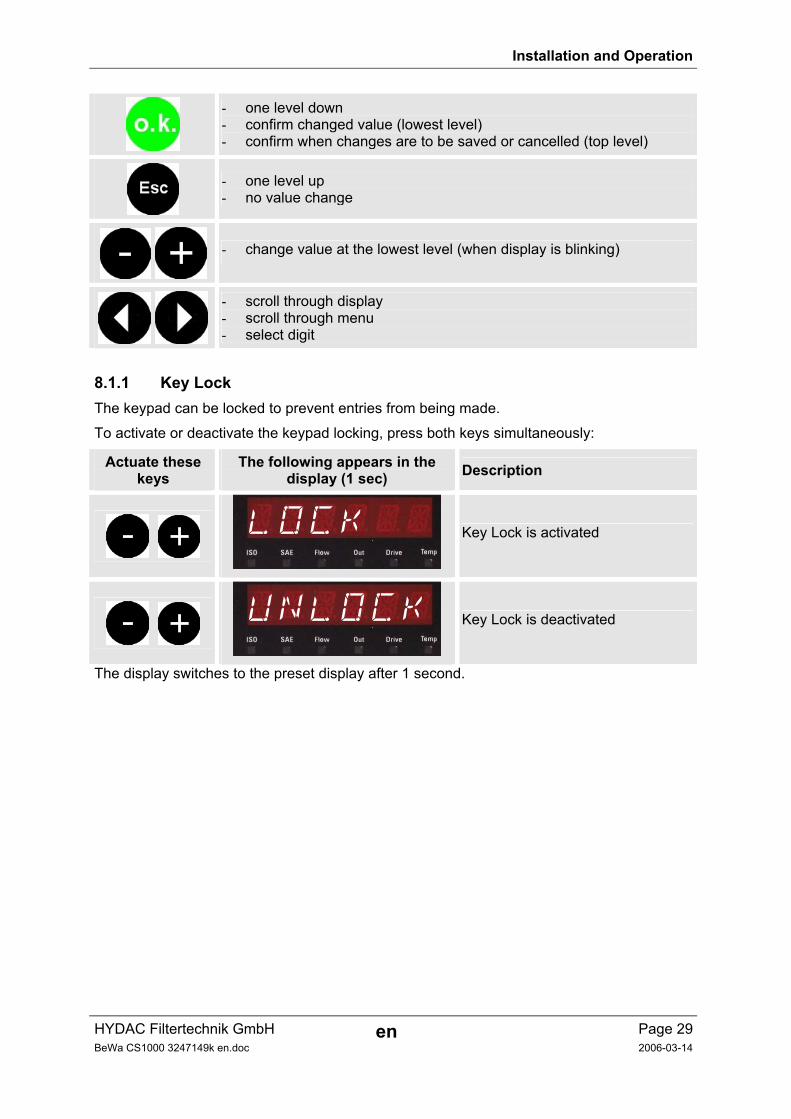
- one level down - confirm changed value (lowest level) - confirm when changes are to be saved or cancelled (top level)
- one level up - no value change
- change value at the lowest level (when display is blinking)
- scroll through display - scroll through menu - select digit
8.1.1 Key Lock The keypad can be locked to prevent entries from being made.
To activate or deactivate the keypad locking, press both keys simultaneously:
Actuate these keys
The following appears in the display (1 sec) Description
LOCK
Key Lock is activated
UNLOCK
Key Lock is deactivated
The display switches to the preset display after 1 second.
Installation and Operation
HYDAC Filtertechnik GmbH en Page 30BeWa CS1000 3247149k en.doc 2006-03-14
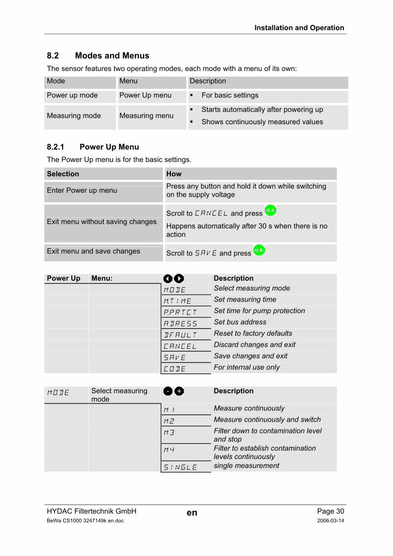
8.2 Modes and Menus The sensor features two operating modes, each mode with a menu of its own:
Mode Menu Description
Power up mode Power Up menu For basic settings
Measuring mode Measuring menu Starts automatically after powering up
Shows continuously measured values
8.2.1 Power Up Menu The Power Up menu is for the basic settings.
Selection How
Enter Power up menu Press any button and hold it down while switching on the supply voltage
Exit menu without saving changes Scroll to CANCEL and press
Happens automatically after 30 s when there is no action
Exit menu and save changes Scroll to SAVE and press
Power Up Menu: Description MODE Select measuring mode mTIME Set measuring time pPRTCT Set time for pump protection ADRESS Set bus address DFAULT Reset to factory defaults CANCEL Discard changes and exit SAVE Save changes and exit CODE For internal use only
MODE Select measuring mode
Description
M1 Measure continuously M2 Measure continuously and switch M3 Filter down to contamination level
and stop M4 Filter to establish contamination
levels continuously SINGLE single measurement
Installation and Operation
HYDAC Filtertechnik GmbH en Page 31BeWa CS1000 3247149k en.doc 2006-03-14
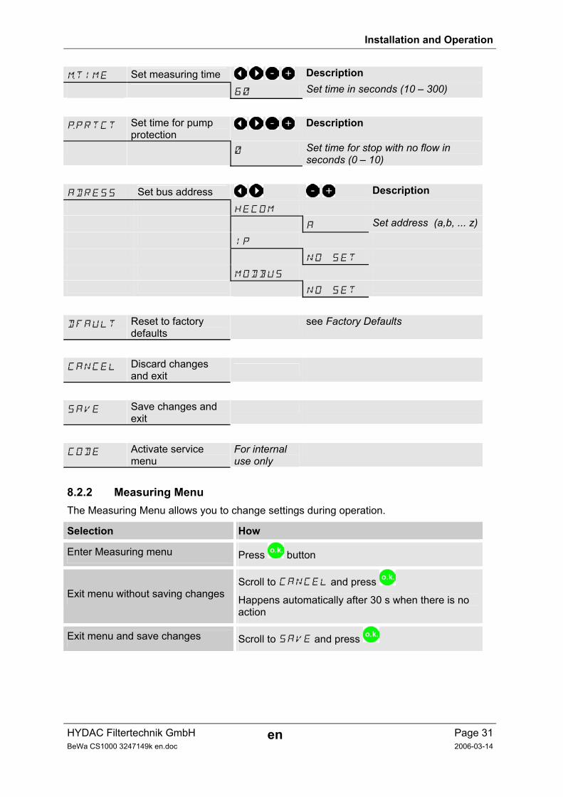
mTIME Set measuring time Description
60 Set time in seconds (10 – 300)
pPRTCT Set time for pump protection
Description
0 Set time for stop with no flow in seconds (0 – 10)
ADRESS Set bus address Description HECOM A Set address (a,b, ... z) IP NO SET MODBUS NO SET
DFAULT Reset to factory defaults
see Factory Defaults
CANCEL Discard changes and exit
SAVE Save changes and exit
CODE Activate service menu
For internal use only
8.2.2 Measuring Menu The Measuring Menu allows you to change settings during operation.
Selection How
Enter Measuring menu Press button
Exit menu without saving changes Scroll to CANCEL and press
Happens automatically after 30 s when there is no action
Exit menu and save changes Scroll to SAVE and press
Installation and Operation
HYDAC Filtertechnik GmbH en Page 32BeWa CS1000 3247149k en.doc 2006-03-14
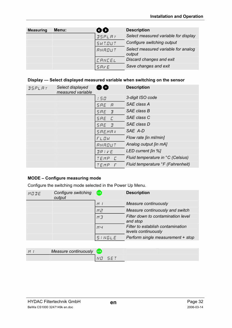
Measuring Menu: Description DSPLAY Select measured variable for display SWtOUT Configure switching output ANaOUT Select measured variable for analog
output CANCEL Discard changes and exit SAVE Save changes and exit
Display — Select displayed measured variable when switching on the sensor
DSPLAY Select displayed measured variable
Description
ISO 3-digit ISO code SAE A SAE class A SAE B SAE class B SAE C SAE class C SAE D SAE class D SAeMAX SAE A-D FLOW Flow rate [in ml/min] ANaOUT Analog output [in mA] DRIVE LED current [in %] TEMP C Fluid temperature in °C (Celsius) TEMP F Fluid temperature °F (Fahrenheit)
MODE – Configure measuring mode Configure the switching mode selected in the Power Up Menu.
MODE Configure switching output
Description
M1 Measure continuously M2 Measure continuously and switch M3 Filter down to contamination level
and stop M4 Filter to establish contamination
levels continuously SINGLE Perform single measurement + stop
M1 Measure continuously NO SET
Installation and Operation
HYDAC Filtertechnik GmbH en Page 33BeWa CS1000 3247149k en.doc 2006-03-14
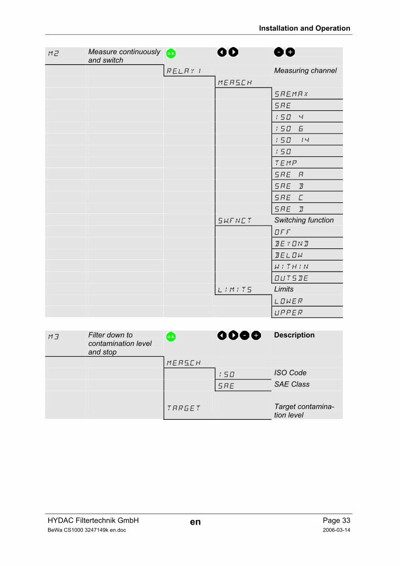
M2 Measure continuously and switch
RelAY1 Measuring channel MEAsCH
SAeMAX
SAE
ISO 4
ISO 6
ISO 14
ISO
TEMP
SAE A
SAE B
SAE C
SAE D
SwFNCT Switching function OFF
BEYOND
BELOW
WITHIN
OUTSDE
LIMITS Limits LOWER
UPPER
M3 Filter down to contamination level and stop
Description
MEAsCH
ISO ISO Code SAE SAE Class
TARGET Target contamina-tion level
Installation and Operation
HYDAC Filtertechnik GmbH en Page 34BeWa CS1000 3247149k en.doc 2006-03-14
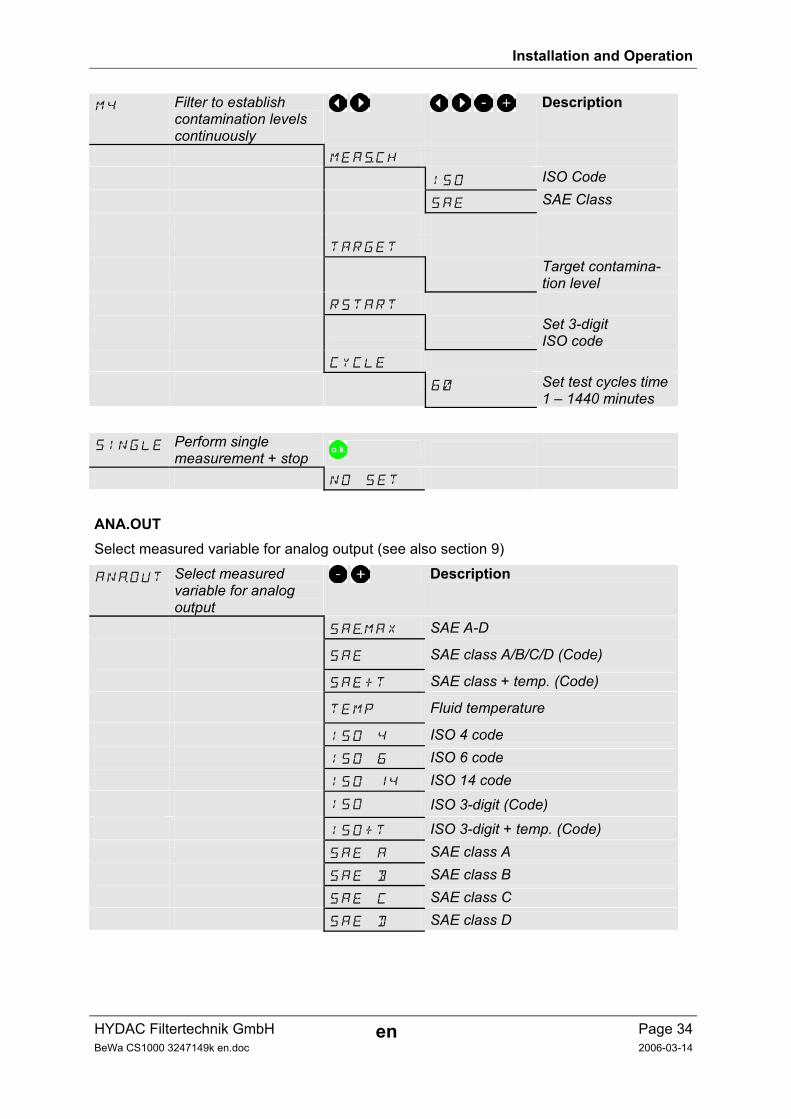
M4 Filter to establish contamination levels continuously
Description
MEAsCH
ISO ISO Code SAE SAE Class
TARGET
Target contamina-tion level
RSTART
Set 3-digit ISO code
CYCLE
60 Set test cycles time1 – 1440 minutes
SINGLE Perform single measurement + stop
NO SET
ANA.OUT Select measured variable for analog output (see also section 9)
ANaOUT Select measured variable for analog output
Description
SAeMAX SAE A-D
SAE SAE class A/B/C/D (Code) SAE+T SAE class + temp. (Code)
TEMP Fluid temperature ISO 4 ISO 4 code ISO 6 ISO 6 code ISO 14 ISO 14 code ISO ISO 3-digit (Code) ISO+T ISO 3-digit + temp. (Code) SAE A SAE class A SAE B SAE class B SAE C SAE class C SAE D SAE class D
Installation and Operation
HYDAC Filtertechnik GmbH en Page 35BeWa CS1000 3247149k en.doc 2006-03-14
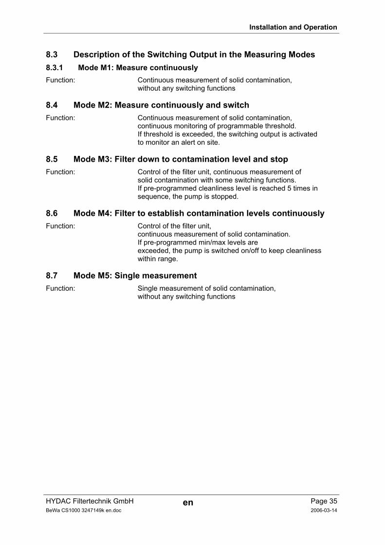
8.3 Description of the Switching Output in the Measuring Modes 8.3.1 Mode M1: Measure continuously Function: Continuous measurement of solid contamination, without any switching functions
8.4 Mode M2: Measure continuously and switch Function: Continuous measurement of solid contamination, continuous monitoring of programmable threshold. If threshold is exceeded, the switching output is activated to monitor an alert on site.
8.5 Mode M3: Filter down to contamination level and stop Function: Control of the filter unit, continuous measurement of solid contamination with some switching functions. If pre-programmed cleanliness level is reached 5 times in sequence, the pump is stopped.
8.6 Mode M4: Filter to establish contamination levels continuously Function: Control of the filter unit, continuous measurement of solid contamination. If pre-programmed min/max levels are exceeded, the pump is switched on/off to keep cleanliness within range.
8.7 Mode M5: Single measurement Function: Single measurement of solid contamination, without any switching functions
Installation and Operation
HYDAC Filtertechnik GmbH en Page 36BeWa CS1000 3247149k en.doc 2006-03-14
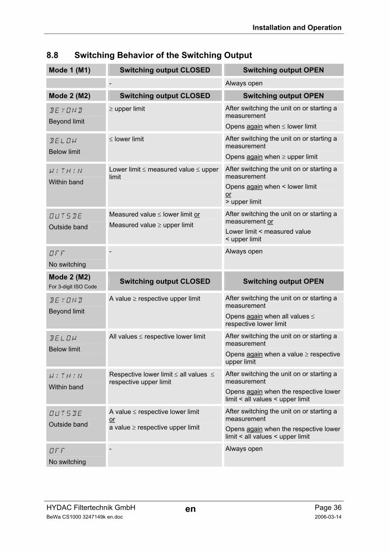
8.8 Switching Behavior of the Switching Output Mode 1 (M1) Switching output CLOSED Switching output OPEN
- Always open
Mode 2 (M2) Switching output CLOSED Switching output OPEN
BEYOND Beyond limit
≥ upper limit After switching the unit on or starting a measurement Opens again when ≤ lower limit
BELOW Below limit
≤ lower limit After switching the unit on or starting a measurement Opens again when ≥ upper limit
WITHIN Within band
Lower limit ≤ measured value ≤ upper limit
After switching the unit on or starting a measurement Opens again when < lower limit or > upper limit
OUTSDE Outside band
Measured value ≤ lower limit or Measured value ≥ upper limit
After switching the unit on or starting a measurement or Lower limit < measured value < upper limit
OFF No switching
- Always open
Mode 2 (M2) For 3-digit ISO Code
Switching output CLOSED Switching output OPEN
BEYOND Beyond limit
A value ≥ respective upper limit After switching the unit on or starting a measurement Opens again when all values ≤ respective lower limit
BELOW Below limit
All values ≤ respective lower limit After switching the unit on or starting a measurement Opens again when a value ≥ respective upper limit
WITHIN Within band
Respective lower limit ≤ all values ≤ respective upper limit
After switching the unit on or starting a measurement Opens again when the respective lower limit < all values < upper limit
OUTSDE Outside band
A value ≤ respective lower limit or a value ≥ respective upper limit
After switching the unit on or starting a measurement Opens again when the respective lower limit < all values < upper limit
OFF No switching
- Always open
Installation and Operation
HYDAC Filtertechnik GmbH en Page 37BeWa CS1000 3247149k en.doc 2006-03-14
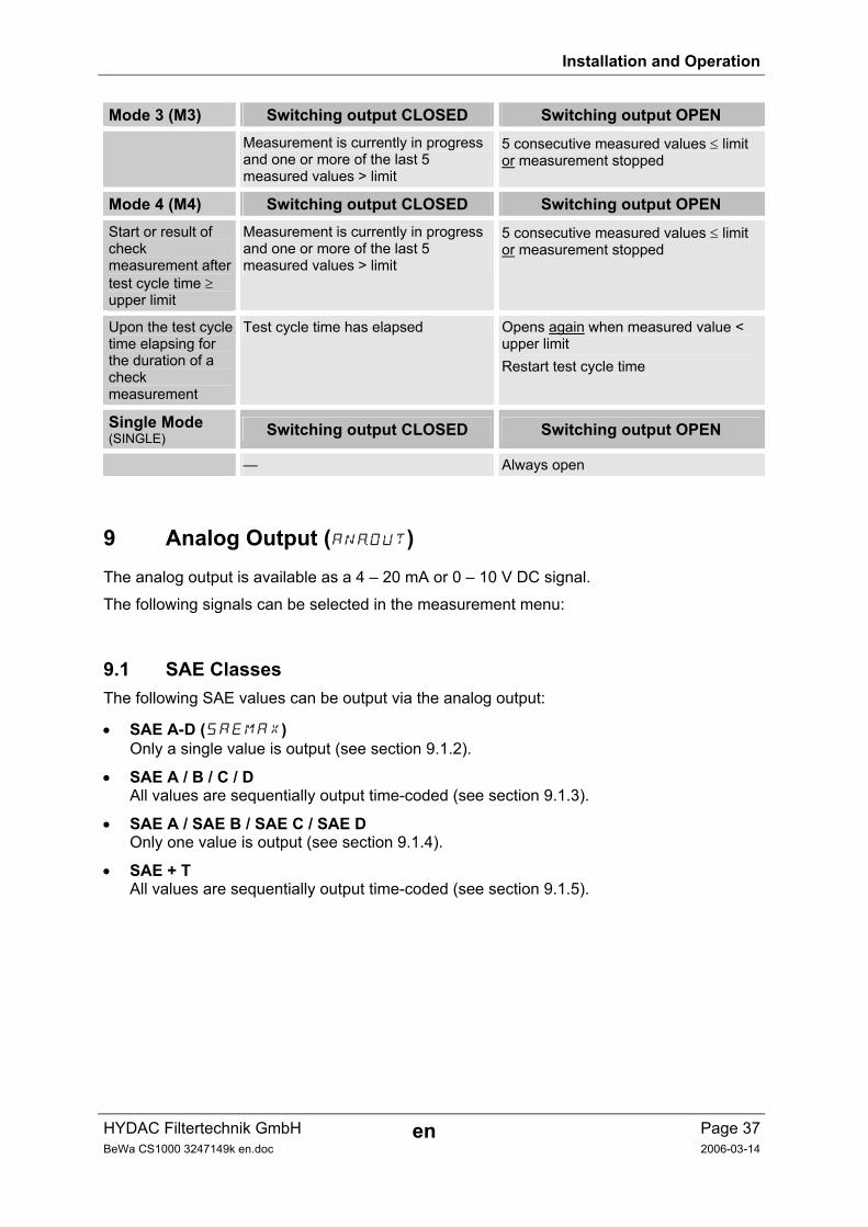
Mode 3 (M3) Switching output CLOSED Switching output OPEN
Measurement is currently in progress and one or more of the last 5 measured values > limit
5 consecutive measured values ≤ limit or measurement stopped
Mode 4 (M4) Switching output CLOSED Switching output OPEN Start or result of check measurement after test cycle time ≥ upper limit
Measurement is currently in progress and one or more of the last 5 measured values > limit
5 consecutive measured values ≤ limit or measurement stopped
Upon the test cycle time elapsing for the duration of a check measurement
Test cycle time has elapsed Opens again when measured value < upper limit Restart test cycle time
Single Mode (SINGLE) Switching output CLOSED Switching output OPEN
— Always open
9 Analog Output (ANaOUT) The analog output is available as a 4 – 20 mA or 0 – 10 V DC signal.
The following signals can be selected in the measurement menu:
9.1 SAE Classes The following SAE values can be output via the analog output:
• SAE A-D (SAEMAX) Only a single value is output (see section 9.1.2).
• SAE A / B / C / D All values are sequentially output time-coded (see section 9.1.3).
• SAE A / SAE B / SAE C / SAE D Only one value is output (see section 9.1.4).
• SAE + T All values are sequentially output time-coded (see section 9.1.5).
Installation and Operation
HYDAC Filtertechnik GmbH en Page 38BeWa CS1000 3247149k en.doc 2006-03-14
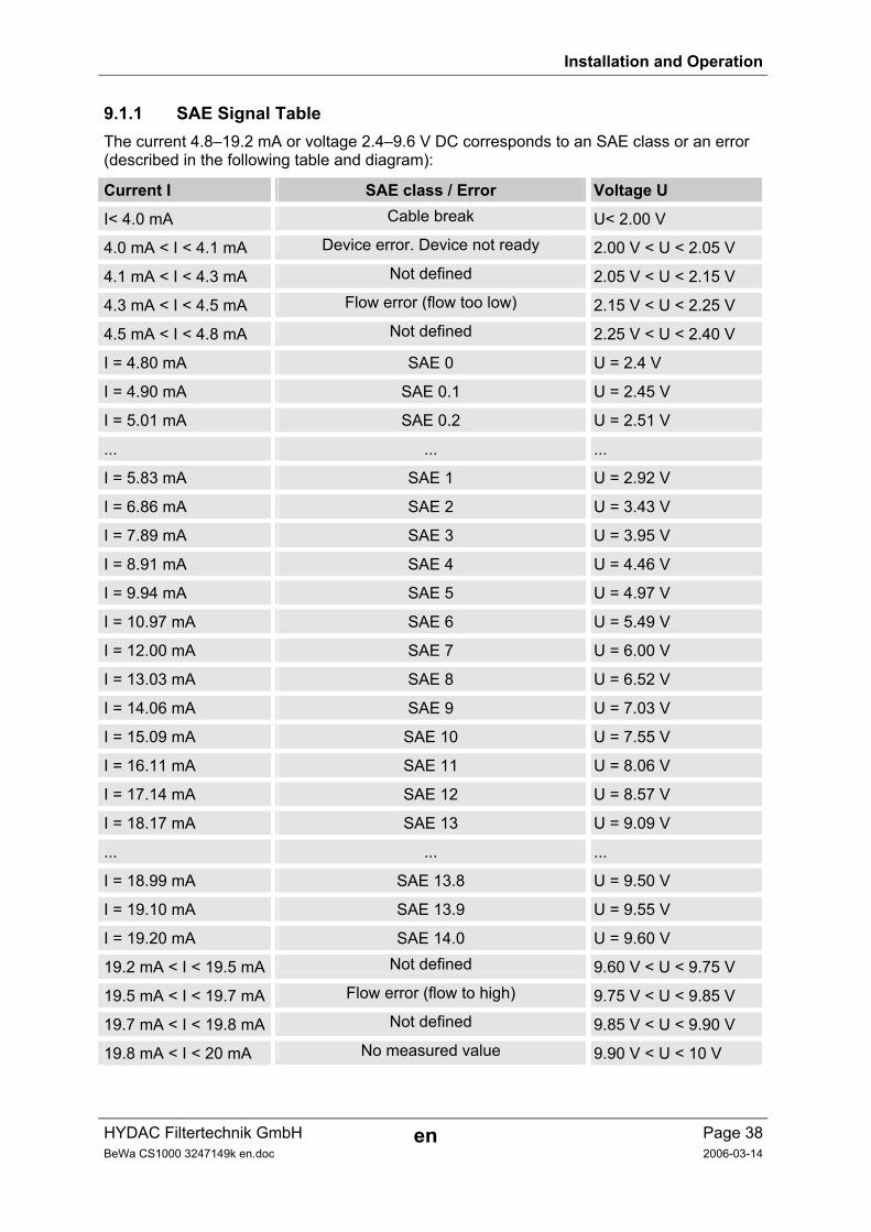
9.1.1 SAE Signal Table The current 4.8–19.2 mA or voltage 2.4–9.6 V DC corresponds to an SAE class or an error (described in the following table and diagram):
Current I SAE class / Error Voltage U
I< 4.0 mA Cable break U< 2.00 V
4.0 mA < I < 4.1 mA Device error. Device not ready 2.00 V < U < 2.05 V
4.1 mA < I < 4.3 mA Not defined 2.05 V < U < 2.15 V
4.3 mA < I < 4.5 mA Flow error (flow too low) 2.15 V < U < 2.25 V
4.5 mA < I < 4.8 mA Not defined 2.25 V < U < 2.40 V
I = 4.80 mA SAE 0 U = 2.4 V
I = 4.90 mA SAE 0.1 U = 2.45 V
I = 5.01 mA SAE 0.2 U = 2.51 V
... ... ...
I = 5.83 mA SAE 1 U = 2.92 V
I = 6.86 mA SAE 2 U = 3.43 V
I = 7.89 mA SAE 3 U = 3.95 V
I = 8.91 mA SAE 4 U = 4.46 V
I = 9.94 mA SAE 5 U = 4.97 V
I = 10.97 mA SAE 6 U = 5.49 V
I = 12.00 mA SAE 7 U = 6.00 V
I = 13.03 mA SAE 8 U = 6.52 V
I = 14.06 mA SAE 9 U = 7.03 V
I = 15.09 mA SAE 10 U = 7.55 V
I = 16.11 mA SAE 11 U = 8.06 V
I = 17.14 mA SAE 12 U = 8.57 V
I = 18.17 mA SAE 13 U = 9.09 V
... ... ...
I = 18.99 mA SAE 13.8 U = 9.50 V
I = 19.10 mA SAE 13.9 U = 9.55 V
I = 19.20 mA SAE 14.0 U = 9.60 V
19.2 mA < I < 19.5 mA Not defined 9.60 V < U < 9.75 V
19.5 mA < I < 19.7 mA Flow error (flow to high) 9.75 V < U < 9.85 V
19.7 mA < I < 19.8 mA Not defined 9.85 V < U < 9.90 V
19.8 mA < I < 20 mA No measured value 9.90 V < U < 10 V
Installation and Operation
HYDAC Filtertechnik GmbH en Page 39BeWa CS1000 3247149k en.doc 2006-03-14
The current I or voltage U can be calculated for a given SAE class as follows: I = 4.8 mA + SAE class * (19.2 mA - 4.8 mA) / 14
U = 2.4 V + SAE class * (9.6 V - 2.4 V) / 14 The SAE class can be calculated for a given current I or voltage U as follows:
SAE class = (I - 4.8 mA)*(14/14.4 mA) SAE class = (U - 2.4 V)*(14/7.2 V)
9.1.2 SAE A-D (SAeMAX)
The SAeMAX value is the highest class in any of one of the four SAE A-D classes (respectively >4 µm(c),>6 µm(c),>14 µm(c),>21 µm(c)).
The signal is updated after the measuring time has elapsed (the measuring time is set in the Power Up menu / default: 60 s).
The SAeMAX signal is a mA signal corresponding to this maximum SAE class.
Example:
SAE classes SAeMAX (SAE A-D)
SAE 6.1A / 5.7B / 6.0C / 5.5D 6.1
For basic information about cleanliness classes, see section 15.
The SAE classification contains integer values only. Better trend recognition is based on a resolution of 0.1 contamination classes as supplied by the CS1000.
To convert a decimal value to an integer, the decimal value has to be rounded up. For example, a readout of SAE 10.7 corresponds to SAE 11.
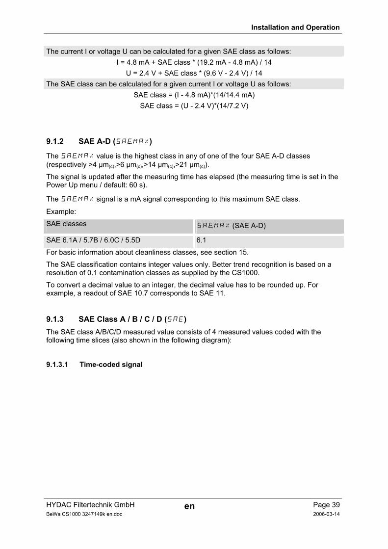
9.1.3 SAE Class A / B / C / D (SAE) The SAE class A/B/C/D measured value consists of 4 measured values coded with the following time slices (also shown in the following diagram):
9.1.3.1 Time-coded signal
Installation and Operation
HYDAC Filtertechnik GmbH en Page 40BeWa CS1000 3247149k en.doc 2006-03-14
9.1.3.1.1 4 – 20 mA Signal Identifier Identifier Identifier Identifier Identifier
Measured Measured Measured Measured value value value value
Tim
e
Size Signal duration per
pulse in ms
Current in mA
Identifier A 300 19.2 / 4.8
Measured value A 3000 Current for measured value (see Table 9.1.1)
Identifier B 300 19.2 / 4.8 / 19.2 / 4.8
Measured value B 3000 Current for measured value (see Table 9.1.1)
Identifier C 300 19.2 / 4.8 / 19.2 / 4.8 / 19.2 / 4.8
Measured value C 3000 Current for measured value (see Table 9.1.1)
Identifier D 300 19.2 / 4.8 / 19.2 / 4.8 / 19.2 / 4.8 / 19.2 / 4.8
Measured value D 3000 Current for measured value (see Table 9.1.1)
Installation and Operation
HYDAC Filtertechnik GmbH en Page 41BeWa CS1000 3247149k en.doc 2006-03-14
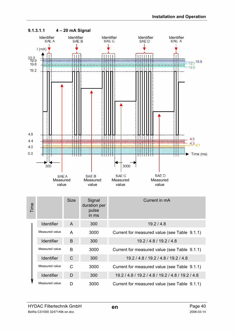
9.1.3.1.2 0 – 10 V Signal Identifier Identifier Identifier Identifier Identifer
Measured Measured Measured Measured value value value value
Tim
e
Size Signal duration per
pulse in ms
Voltage in V
Identifier A 300 9.6 / 2.4
Measured value A 3000 Voltage for measured value (see Table 9.1.1)
Identifier B 300 9.6 / 2.4 / 9.6 / 2.4
Measured value B 3000 Voltage for measured value (see Table 9.1.1)
Identifier C 300 9.6 / 2.4 / 9.6 / 2.4 / 9.6 / 2.4
Measured value C 3000 Voltage for measured value (see Table 9.1.1)
Identifier D 300 9.6 / 2.4 / 9.6 / 2.4 / 9.6 / 2.4 / 9.6 / 2.4
Measured value D 3000 Voltage for measured value (see Table 9.1.1)
Installation and Operation
HYDAC Filtertechnik GmbH en Page 42BeWa CS1000 3247149k en.doc 2006-03-14
9.1.4 SAE A / SAE B / SAE C / SAE D (SAE A/SAE B/SAE C/SAE D) The SAE x setting enables the value of a class to be continuously output via the analog output.
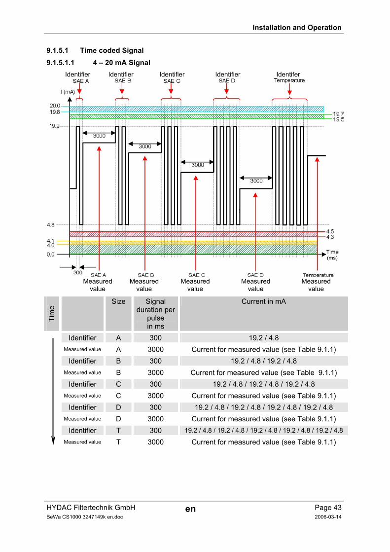
9.1.5 SAE + T (SAE+T) The SAE+T signal consists of 5 measured values which are transmitted time-coded with the following time slices:
Installation and Operation
HYDAC Filtertechnik GmbH en Page 43BeWa CS1000 3247149k en.doc 2006-03-14
9.1.5.1 Time coded Signal 9.1.5.1.1 4 – 20 mA Signal
Identifier Identifier Identifier Identifier Identifer
(ms)
Measured Measured Measured Measured Measured value value value value value
Tim
e
Size Signal duration per
pulse in ms
Current in mA
Identifier A 300 19.2 / 4.8 Measured value A 3000 Current for measured value (see Table 9.1.1) Identifier B 300 19.2 / 4.8 / 19.2 / 4.8 Measured value B 3000 Current for measured value (see Table 9.1.1) Identifier C 300 19.2 / 4.8 / 19.2 / 4.8 / 19.2 / 4.8 Measured value C 3000 Current for measured value (see Table 9.1.1) Identifier D 300 19.2 / 4.8 / 19.2 / 4.8 / 19.2 / 4.8 / 19.2 / 4.8 Measured value D 3000 Current for measured value (see Table 9.1.1) Identifier T 300 19.2 / 4.8 / 19.2 / 4.8 / 19.2 / 4.8 / 19.2 / 4.8 / 19.2 / 4.8
Measured value T 3000 Current for measured value (see Table 9.1.1)
Installation and Operation
HYDAC Filtertechnik GmbH en Page 44BeWa CS1000 3247149k en.doc 2006-03-14
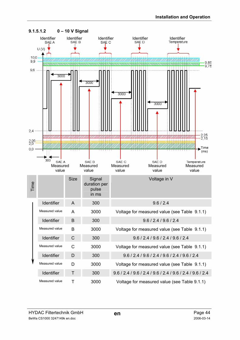
9.1.5.1.2 0 – 10 V Signal Identifier Identifier Identifier Identifier Identifier
(ms)
Measured Measured Measured Measured Measured value value value value value
Tim
e
Size Signal duration per
pulse in ms
Voltage in V
Identifier A 300 9.6 / 2.4
Measured value A 3000 Voltage for measured value (see Table 9.1.1)
Identifier B 300 9.6 / 2.4 / 9.6 / 2.4
Measured value B 3000 Voltage for measured value (see Table 9.1.1)
Identifier C 300 9.6 / 2.4 / 9.6 / 2.4 / 9.6 / 2.4
Measured value C 3000 Voltage for measured value (see Table 9.1.1)
Identifier D 300 9.6 / 2.4 / 9.6 / 2.4 / 9.6 / 2.4 / 9.6 / 2.4
Measured value D 3000 Voltage for measured value (see Table 9.1.1)
Identifier T 300 9.6 / 2.4 / 9.6 / 2.4 / 9.6 / 2.4 / 9.6 / 2.4 / 9.6 / 2.4
Measured value T 3000 Voltage for measured value (see Table 9.1.1)
Installation and Operation
HYDAC Filtertechnik GmbH en Page 45BeWa CS1000 3247149k en.doc 2006-03-14
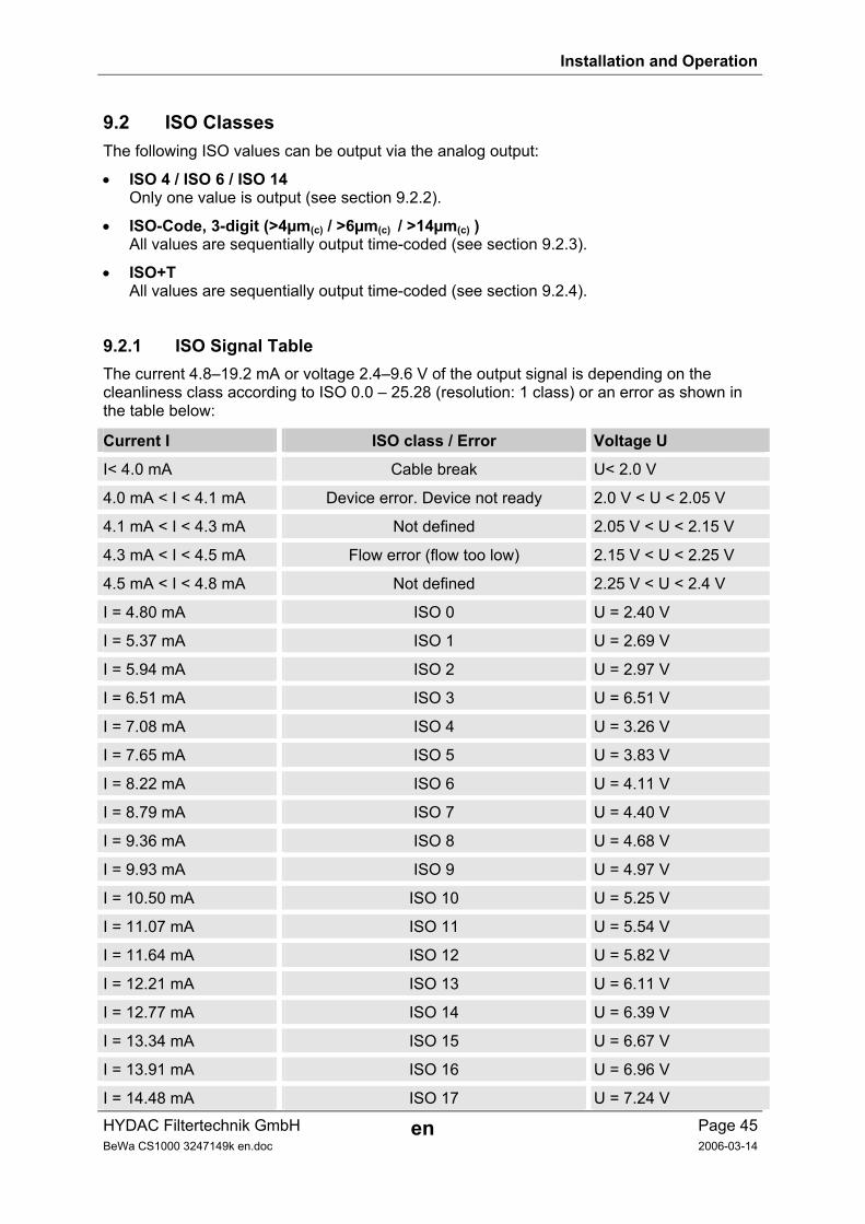
9.2 ISO Classes The following ISO values can be output via the analog output:
• ISO 4 / ISO 6 / ISO 14 Only one value is output (see section 9.2.2).
• ISO-Code, 3-digit (>4µm(c) / >6µm(c) / >14µm(c) ) All values are sequentially output time-coded (see section 9.2.3).
• ISO+T All values are sequentially output time-coded (see section 9.2.4).
9.2.1 ISO Signal Table The current 4.8–19.2 mA or voltage 2.4–9.6 V of the output signal is depending on the cleanliness class according to ISO 0.0 – 25.28 (resolution: 1 class) or an error as shown in the table below:
Current I ISO class / Error Voltage U
I< 4.0 mA Cable break U< 2.0 V
4.0 mA < I < 4.1 mA Device error. Device not ready 2.0 V < U < 2.05 V
4.1 mA < I < 4.3 mA Not defined 2.05 V < U < 2.15 V
4.3 mA < I < 4.5 mA Flow error (flow too low) 2.15 V < U < 2.25 V
4.5 mA < I < 4.8 mA Not defined 2.25 V < U < 2.4 V
I = 4.80 mA ISO 0 U = 2.40 V
I = 5.37 mA ISO 1 U = 2.69 V
I = 5.94 mA ISO 2 U = 2.97 V
I = 6.51 mA ISO 3 U = 6.51 V
I = 7.08 mA ISO 4 U = 3.26 V
I = 7.65 mA ISO 5 U = 3.83 V
I = 8.22 mA ISO 6 U = 4.11 V
I = 8.79 mA ISO 7 U = 4.40 V
I = 9.36 mA ISO 8 U = 4.68 V
I = 9.93 mA ISO 9 U = 4.97 V
I = 10.50 mA ISO 10 U = 5.25 V
I = 11.07 mA ISO 11 U = 5.54 V
I = 11.64 mA ISO 12 U = 5.82 V
I = 12.21 mA ISO 13 U = 6.11 V
I = 12.77 mA ISO 14 U = 6.39 V
I = 13.34 mA ISO 15 U = 6.67 V
I = 13.91 mA ISO 16 U = 6.96 V
I = 14.48 mA ISO 17 U = 7.24 V
Installation and Operation
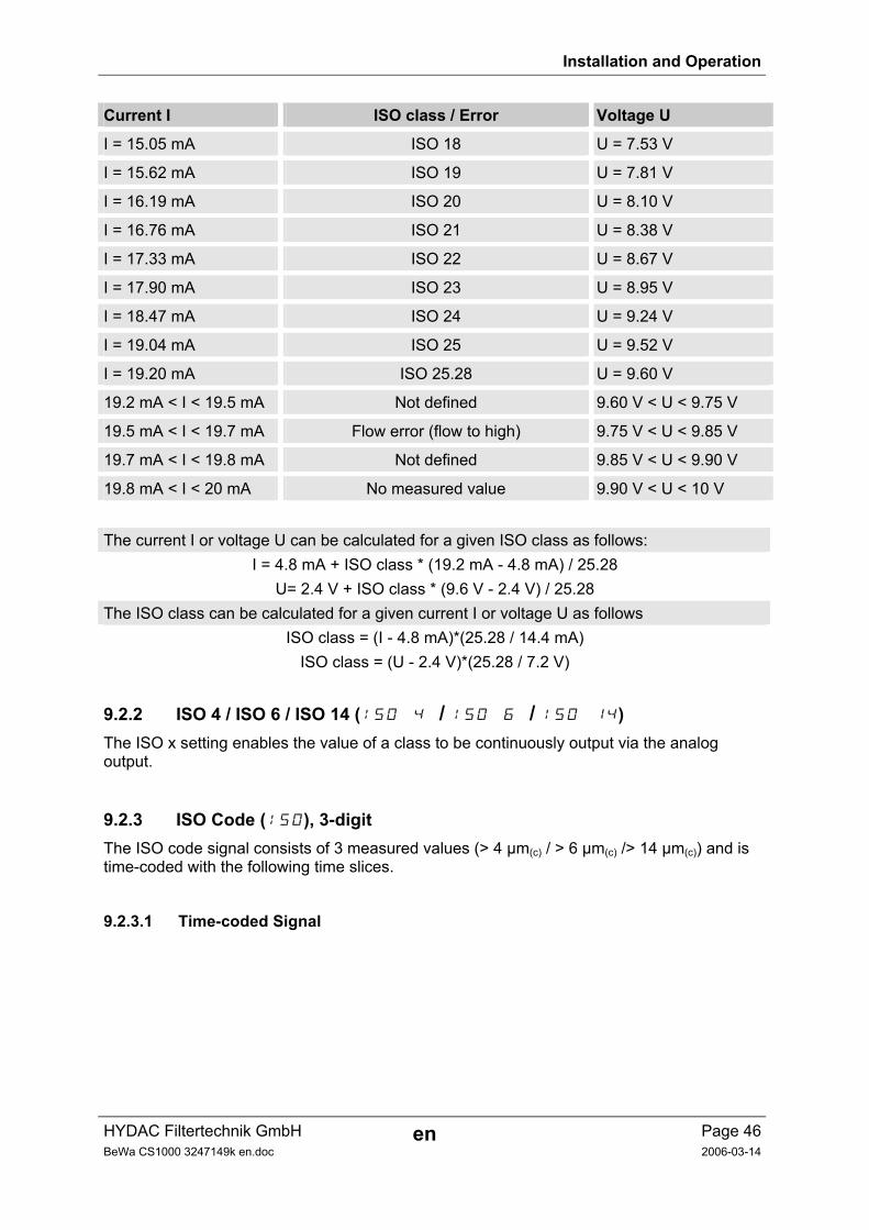
HYDAC Filtertechnik GmbH en Page 46BeWa CS1000 3247149k en.doc 2006-03-14
Current I ISO class / Error Voltage U
I = 15.05 mA ISO 18 U = 7.53 V
I = 15.62 mA ISO 19 U = 7.81 V
I = 16.19 mA ISO 20 U = 8.10 V
I = 16.76 mA ISO 21 U = 8.38 V
I = 17.33 mA ISO 22 U = 8.67 V
I = 17.90 mA ISO 23 U = 8.95 V
I = 18.47 mA ISO 24 U = 9.24 V
I = 19.04 mA ISO 25 U = 9.52 V
I = 19.20 mA ISO 25.28 U = 9.60 V
19.2 mA < I < 19.5 mA Not defined 9.60 V < U < 9.75 V
19.5 mA < I < 19.7 mA Flow error (flow to high) 9.75 V < U < 9.85 V
19.7 mA < I < 19.8 mA Not defined 9.85 V < U < 9.90 V
19.8 mA < I < 20 mA No measured value 9.90 V < U < 10 V
The current I or voltage U can be calculated for a given ISO class as follows: I = 4.8 mA + ISO class * (19.2 mA - 4.8 mA) / 25.28
U= 2.4 V + ISO class * (9.6 V - 2.4 V) / 25.28 The ISO class can be calculated for a given current I or voltage U as follows
ISO class = (I - 4.8 mA)*(25.28 / 14.4 mA) ISO class = (U - 2.4 V)*(25.28 / 7.2 V)
9.2.2 ISO 4 / ISO 6 / ISO 14 (ISO 4 / ISO 6 / ISO 14) The ISO x setting enables the value of a class to be continuously output via the analog output.
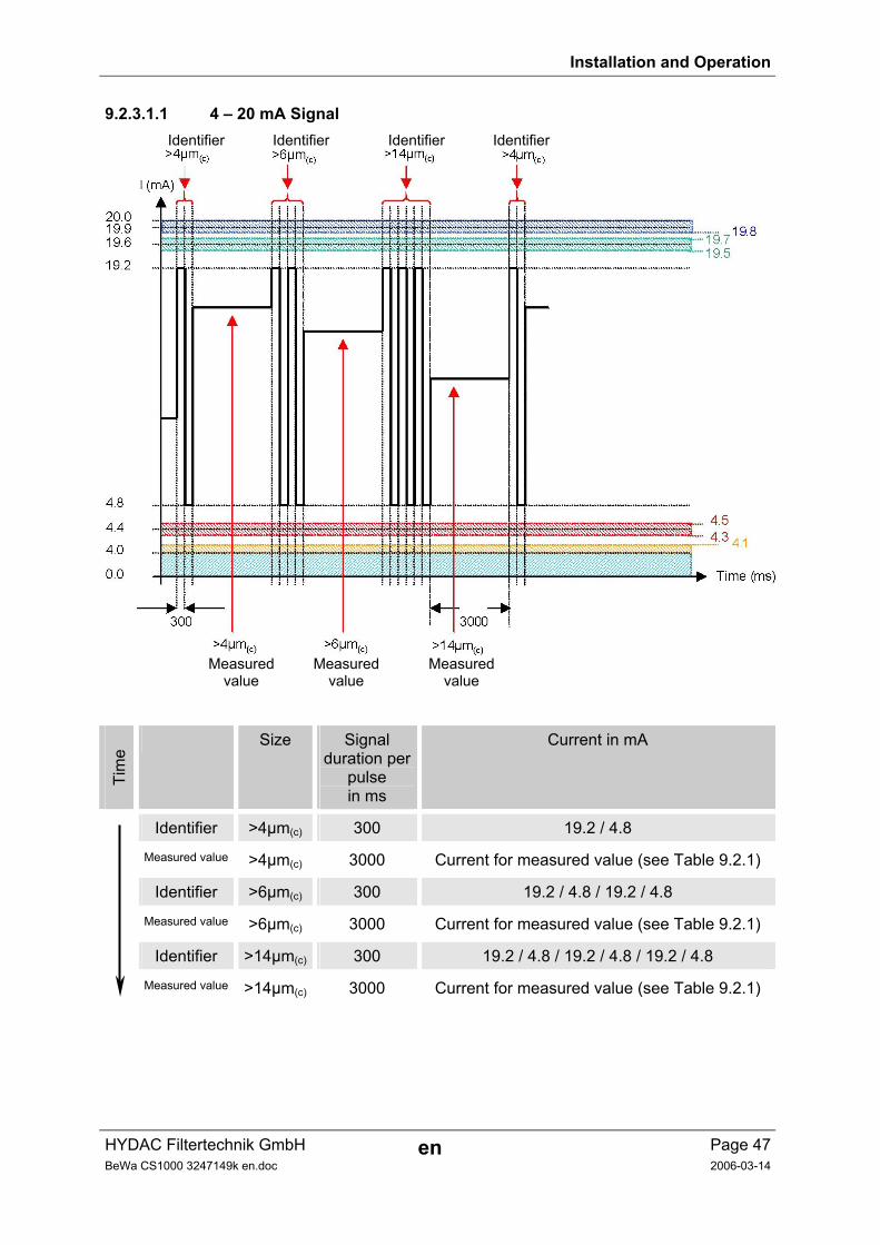
9.2.3 ISO Code (ISO), 3-digit The ISO code signal consists of 3 measured values (> 4 µm(c) / > 6 µm(c) /> 14 µm(c)) and is time-coded with the following time slices.
9.2.3.1 Time-coded Signal
Installation and Operation
HYDAC Filtertechnik GmbH en Page 47BeWa CS1000 3247149k en.doc 2006-03-14
9.2.3.1.1 4 – 20 mA Signal Identifier Identifier Identifier Identifier
Measured Measured Measured value value value
Tim
e
Size Signal duration per
pulse in ms
Current in mA
Identifier >4µm(c) 300 19.2 / 4.8
Measured value >4µm(c) 3000 Current for measured value (see Table 9.2.1)
Identifier >6µm(c) 300 19.2 / 4.8 / 19.2 / 4.8
Measured value >6µm(c) 3000 Current for measured value (see Table 9.2.1)
Identifier >14µm(c) 300 19.2 / 4.8 / 19.2 / 4.8 / 19.2 / 4.8
Measured value >14µm(c) 3000 Current for measured value (see Table 9.2.1)
Installation and Operation
HYDAC Filtertechnik GmbH en Page 48BeWa CS1000 3247149k en.doc 2006-03-14
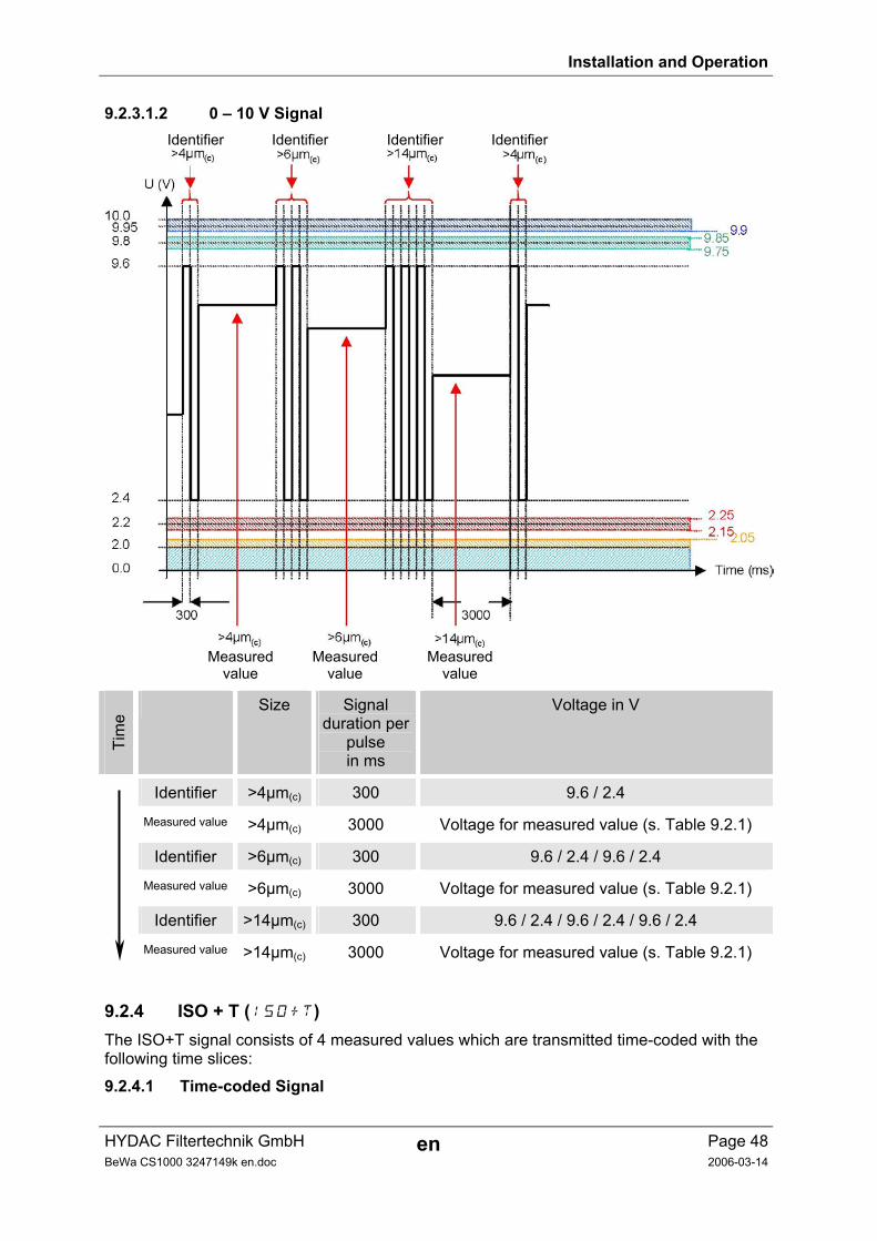
9.2.3.1.2 0 – 10 V Signal Identifier Identifier Identifier Identifier
Measured Measured Measured value value value
Tim
e
Size Signal duration per
pulse in ms
Voltage in V
Identifier >4µm(c) 300 9.6 / 2.4
Measured value >4µm(c) 3000 Voltage for measured value (s. Table 9.2.1)
Identifier >6µm(c) 300 9.6 / 2.4 / 9.6 / 2.4
Measured value >6µm(c) 3000 Voltage for measured value (s. Table 9.2.1)
Identifier >14µm(c) 300 9.6 / 2.4 / 9.6 / 2.4 / 9.6 / 2.4
Measured value >14µm(c) 3000 Voltage for measured value (s. Table 9.2.1)
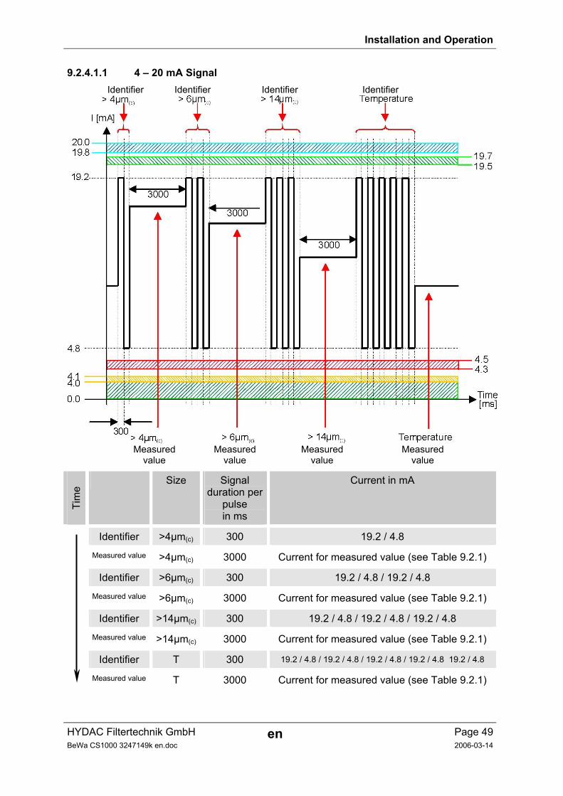
9.2.4 ISO + T (ISO+T) The ISO+T signal consists of 4 measured values which are transmitted time-coded with the following time slices:
9.2.4.1 Time-coded Signal
Installation and Operation
HYDAC Filtertechnik GmbH en Page 49BeWa CS1000 3247149k en.doc 2006-03-14
9.2.4.1.1 4 – 20 mA Signal Identifier Identifier Identifier Identifier
Measured Measured Measured Measured value value value value
Tim
e
Size Signal duration per
pulse in ms
Current in mA
Identifier >4µm(c) 300 19.2 / 4.8
Measured value >4µm(c) 3000 Current for measured value (see Table 9.2.1)
Identifier >6µm(c) 300 19.2 / 4.8 / 19.2 / 4.8
Measured value >6µm(c) 3000 Current for measured value (see Table 9.2.1)
Identifier >14µm(c) 300 19.2 / 4.8 / 19.2 / 4.8 / 19.2 / 4.8
Measured value >14µm(c) 3000 Current for measured value (see Table 9.2.1)
Identifier T 300 19.2 / 4.8 / 19.2 / 4.8 / 19.2 / 4.8 / 19.2 / 4.8 19.2 / 4.8
Measured value T 3000 Current for measured value (see Table 9.2.1)
Installation and Operation
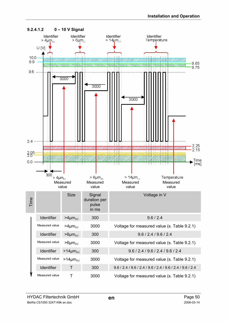
HYDAC Filtertechnik GmbH en Page 50BeWa CS1000 3247149k en.doc 2006-03-14
9.2.4.1.2 0 – 10 V Signal Identifier Identifier Identifier Identifier
Measured Measured Measured Measured value value value value
Tim
e
Size Signal duration per
pulse in ms
Voltage in V
Identifier >4µm(c) 300 9.6 / 2.4
Measured value >4µm(c) 3000 Voltage for measured value (s. Table 9.2.1)
Identifier >6µm(c) 300 9.6 / 2.4 / 9.6 / 2.4
Measured value >6µm(c) 3000 Voltage for measured value (s. Table 9.2.1)
Identifier >14µm(c) 300 9.6 / 2.4 / 9.6 / 2.4 / 9.6 / 2.4
Measured value >14µm(c) 3000 Voltage for measured value (s. Table 9.2.1)
Identifier T 300 9.6 / 2.4 / 9.6 / 2.4 / 9.6 / 2.4 / 9.6 / 2.4 / 9.6 / 2.4
Measured value T 3000 Voltage for measured value (s. Table 9.2.1)
Installation and Operation
HYDAC Filtertechnik GmbH en Page 51BeWa CS1000 3247149k en.doc 2006-03-14
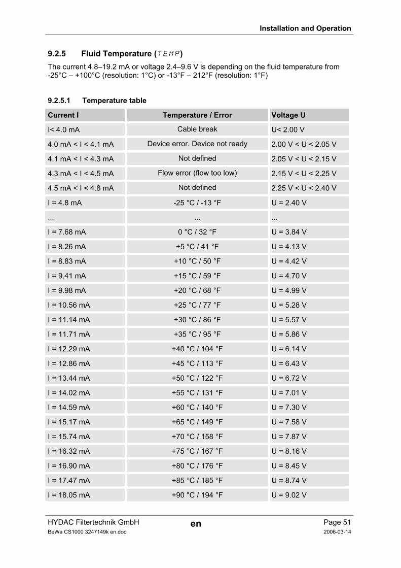
9.2.5 Fluid Temperature (TEMP) The current 4.8–19.2 mA or voltage 2.4–9.6 V is depending on the fluid temperature from -25°C – +100°C (resolution: 1°C) or -13°F – 212°F (resolution: 1°F)
9.2.5.1 Temperature table
Current I Temperature / Error Voltage U
I< 4.0 mA Cable break U< 2.00 V
4.0 mA < I < 4.1 mA Device error. Device not ready 2.00 V < U < 2.05 V
4.1 mA < I < 4.3 mA Not defined 2.05 V < U < 2.15 V
4.3 mA < I < 4.5 mA Flow error (flow too low) 2.15 V < U < 2.25 V
4.5 mA < I < 4.8 mA Not defined 2.25 V < U < 2.40 V
I = 4.8 mA -25 °C / -13 °F U = 2.40 V
... ... ...
I = 7.68 mA 0 °C / 32 °F U = 3.84 V
I = 8.26 mA +5 °C / 41 °F U = 4.13 V
I = 8.83 mA +10 °C / 50 °F U = 4.42 V
I = 9.41 mA +15 °C / 59 °F U = 4.70 V
I = 9.98 mA +20 °C / 68 °F U = 4.99 V
I = 10.56 mA +25 °C / 77 °F U = 5.28 V
I = 11.14 mA +30 °C / 86 °F U = 5.57 V
I = 11.71 mA +35 °C / 95 °F U = 5.86 V
I = 12.29 mA +40 °C / 104 °F U = 6.14 V
I = 12.86 mA +45 °C / 113 °F U = 6.43 V
I = 13.44 mA +50 °C / 122 °F U = 6.72 V
I = 14.02 mA +55 °C / 131 °F U = 7.01 V
I = 14.59 mA +60 °C / 140 °F U = 7.30 V
I = 15.17 mA +65 °C / 149 °F U = 7.58 V
I = 15.74 mA +70 °C / 158 °F U = 7.87 V
I = 16.32 mA +75 °C / 167 °F U = 8.16 V
I = 16.90 mA +80 °C / 176 °F U = 8.45 V
I = 17.47 mA +85 °C / 185 °F U = 8.74 V
I = 18.05 mA +90 °C / 194 °F U = 9.02 V
Installation and Operation
HYDAC Filtertechnik GmbH en Page 52BeWa CS1000 3247149k en.doc 2006-03-14
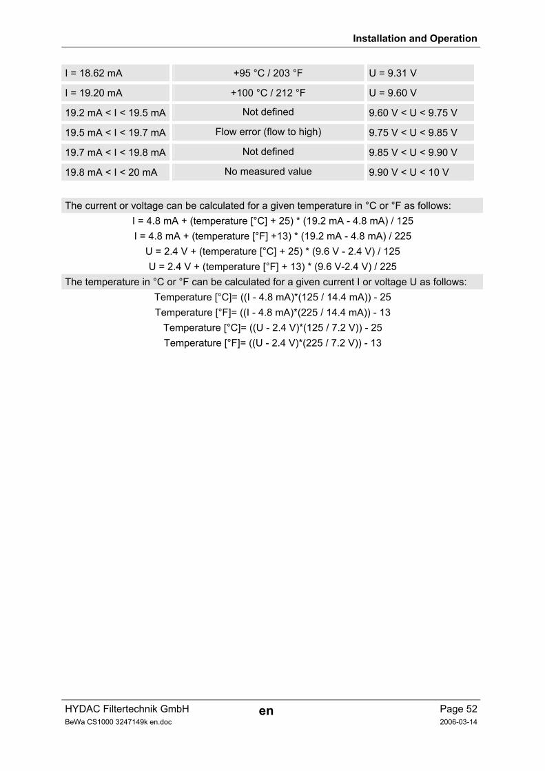
I = 18.62 mA +95 °C / 203 °F U = 9.31 V
I = 19.20 mA +100 °C / 212 °F U = 9.60 V
19.2 mA < I < 19.5 mA Not defined 9.60 V < U < 9.75 V
19.5 mA < I < 19.7 mA Flow error (flow to high) 9.75 V < U < 9.85 V
19.7 mA < I < 19.8 mA Not defined 9.85 V < U < 9.90 V
19.8 mA < I < 20 mA No measured value 9.90 V < U < 10 V
The current or voltage can be calculated for a given temperature in °C or °F as follows: I = 4.8 mA + (temperature [°C] + 25) * (19.2 mA - 4.8 mA) / 125 I = 4.8 mA + (temperature [°F] +13) * (19.2 mA - 4.8 mA) / 225
U = 2.4 V + (temperature [°C] + 25) * (9.6 V - 2.4 V) / 125 U = 2.4 V + (temperature [°F] + 13) * (9.6 V-2.4 V) / 225
The temperature in °C or °F can be calculated for a given current I or voltage U as follows: Temperature [°C]= ((I - 4.8 mA)*(125 / 14.4 mA)) - 25 Temperature [°F]= ((I - 4.8 mA)*(225 / 14.4 mA)) - 13
Temperature [°C]= ((U - 2.4 V)*(125 / 7.2 V)) - 25 Temperature [°F]= ((U - 2.4 V)*(225 / 7.2 V)) - 13
RS-485 Interface
HYDAC Filtertechnik GmbH en Page 53BeWa CS1000 3247149k en.doc 2006-03-14
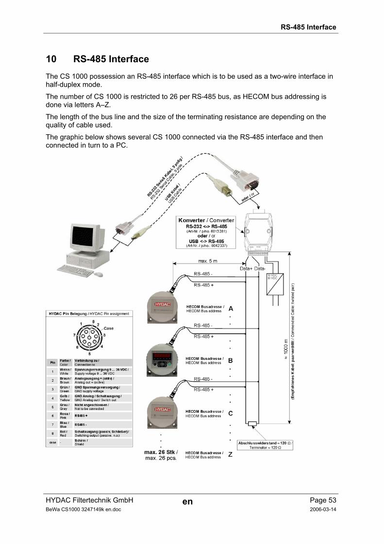
10 RS-485 Interface The CS 1000 possession an RS-485 interface which is to be used as a two-wire interface in half-duplex mode.
The number of CS 1000 is restricted to 26 per RS-485 bus, as HECOM bus addressing is done via letters A–Z.
The length of the bus line and the size of the terminating resistance are depending on the quality of cable used.
The graphic below shows several CS 1000 connected via the RS-485 interface and then connected in turn to a PC.
Condition Sensor Interface CSI
HYDAC Filtertechnik GmbH en Page 54BeWa CS1000 3247149k en.doc 2006-02-14
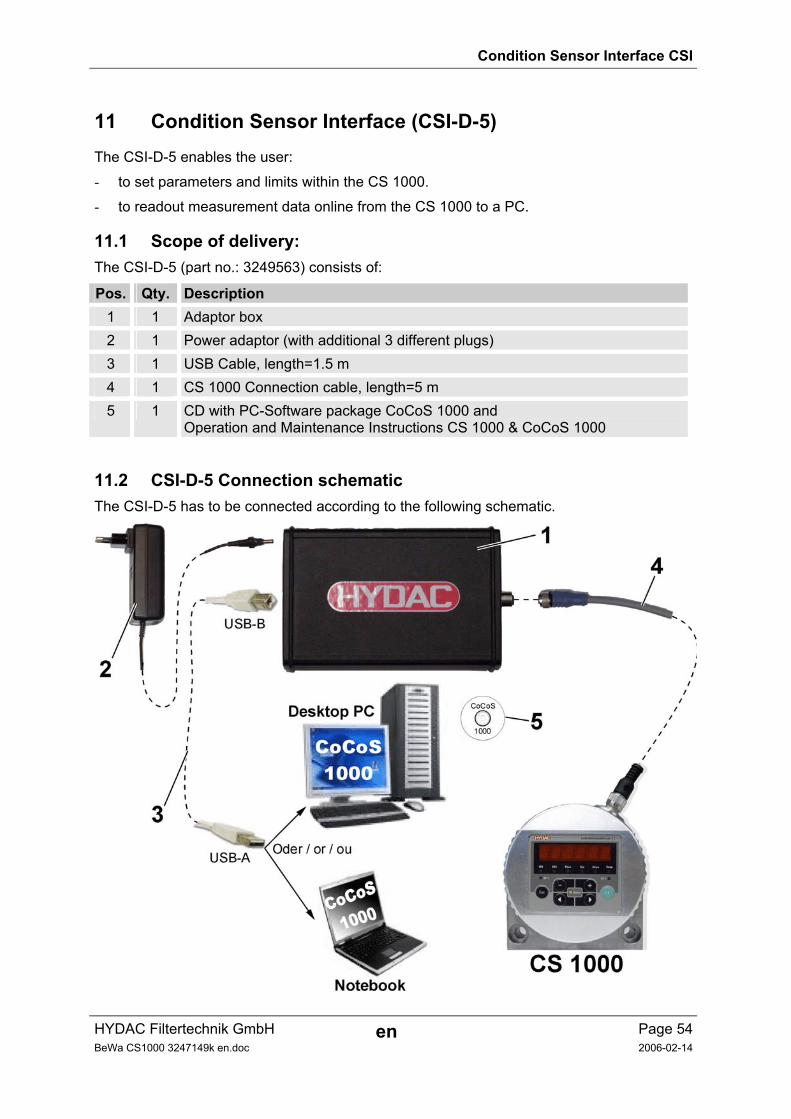
11 Condition Sensor Interface (CSI-D-5) The CSI-D-5 enables the user:
- to set parameters and limits within the CS 1000.
- to readout measurement data online from the CS 1000 to a PC.
11.1 Scope of delivery: The CSI-D-5 (part no.: 3249563) consists of:
Pos. Qty. Description 1 1 Adaptor box 2 1 Power adaptor (with additional 3 different plugs) 3 1 USB Cable, length=1.5 m 4 1 CS 1000 Connection cable, length=5 m 5 1 CD with PC-Software package CoCoS 1000 and
Operation and Maintenance Instructions CS 1000 & CoCoS 1000
11.2 CSI-D-5 Connection schematic The CSI-D-5 has to be connected according to the following schematic.
Condition Sensor Interface CSI
HYDAC Filtertechnik GmbH en Page 55BeWa CS1000 3247149k en.doc 2006-02-14
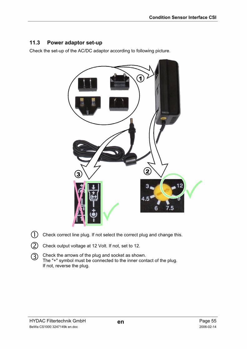
11.3 Power adaptor set-up Check the set-up of the AC/DC adaptor according to following picture.
Check correct line plug. If not select the correct plug and change this.
Check output voltage at 12 Volt. If not, set to 12.
Check the arrows of the plug and socket as shown. The "+" symbol must be connected to the inner contact of the plug. If not, reverse the plug.
CoCoS 1000
HYDAC Filtertechnik GmbH en Page 56BeWa CS1000 3247149k en.doc 2006-03-14
12 Contamination Control Software 1000 (CoCoS 1000)
12.1 General Remarks The CoCoS 1000 PC software pack is freeware.
The software is supplied on a CD which comes standard with the CS 1000 and CSI-D-5 Condition Sensor Interface. (CoCoS 1000 PC software = part/no. 3251484).
The current version of the CoCoS 1000 software is available for download from our website: www.hydac.com E-Business Download Software Service Technology.
12.2 System Requirements Pentium processor 200 MHz or higher
Operating system: Windows 2000, ME, XP
128 MB RAM
VGA graphic card with a resolution of 800x600 or higher
Color monitor with a resolution of 800x600 or higher
Hard disk with a minimum of 75 MB free disk space
Microsoft Windows-compatible mouse
One unused USB port
In order to install the software, you must have administrator rights or rights enabling you to install the software in an unimpeded manner.
12.3 Adaptor Box — Driver Installation Before installing the software package, the CSI-D-5 must be installed.
1) Connect the CSI-D-5 to the CS 1000 and to the power supply as shown in section 11.
2) Connect the adaptor box to your PC via the USB cable. Your PC shows you the new hardware.
If you do not have a driver installed, your PC will ask you to insert a driver CD.
The CoCoS 1000 setup makes a note of the USB port during installation. Installation may have to be repeated if you use different USB port later on.
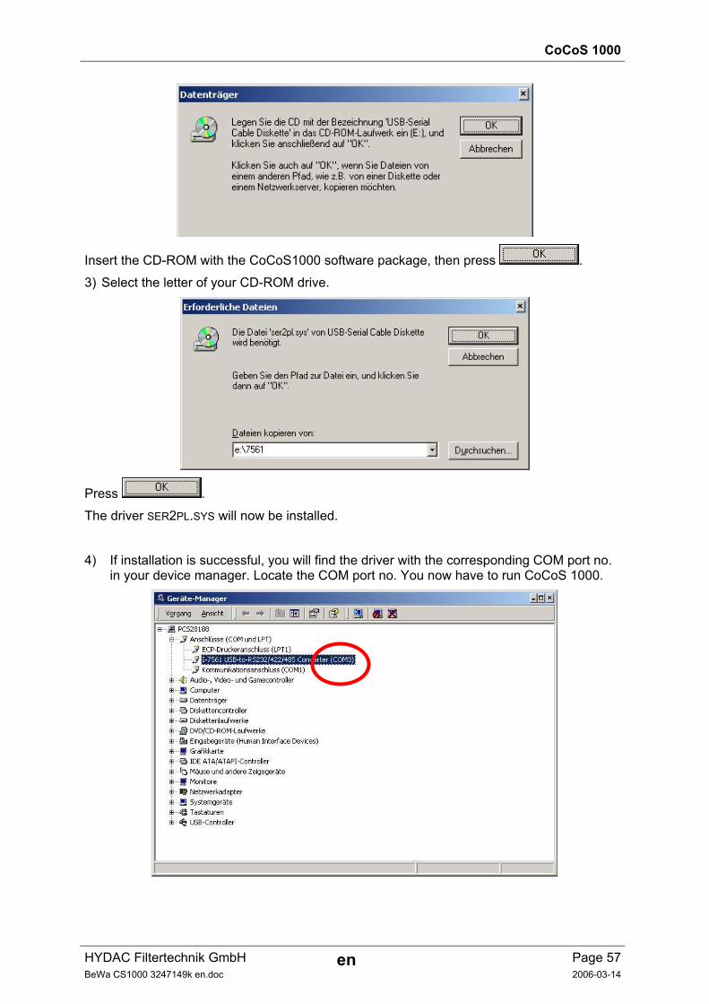
CoCoS 1000
HYDAC Filtertechnik GmbH en Page 57BeWa CS1000 3247149k en.doc 2006-03-14
Insert the CD-ROM with the CoCoS1000 software package, then press .
3) Select the letter of your CD-ROM drive.
Press .
The driver SER2PL.SYS will now be installed.
4) If installation is successful, you will find the driver with the corresponding COM port no. in your device manager. Locate the COM port no. You now have to run CoCoS 1000.
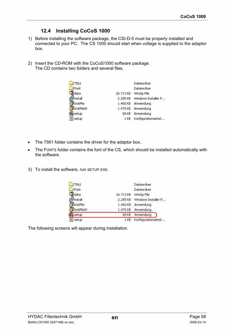
CoCoS 1000
HYDAC Filtertechnik GmbH en Page 58BeWa CS1000 3247149k en.doc 2006-03-14
12.4 Installing CoCoS 1000 1) Before installing the software package, the CSI-D-5 must be properly installed and
connected to your PC. The CS 1000 should start when voltage is supplied to the adaptor box.
2) Insert the CD-ROM with the CoCoS1000 software package. The CD contains two folders and several files.
• The 7561 folder contains the driver for the adaptor box.
• The FONTS folder contains the font of the CS, which should be installed automatically with the software.
3) To install the software, run SETUP.EXE.
The following screens will appear during installation.
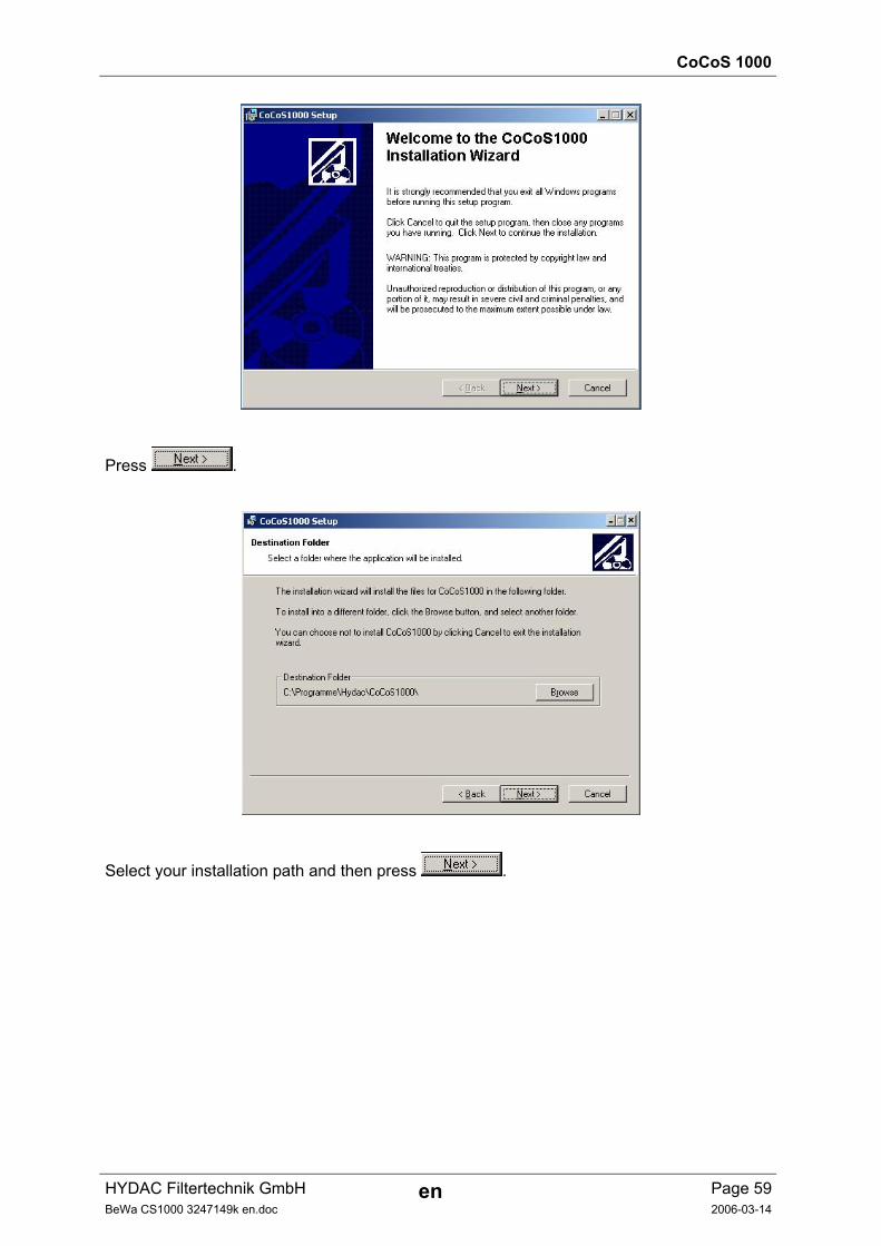
CoCoS 1000
HYDAC Filtertechnik GmbH en Page 59BeWa CS1000 3247149k en.doc 2006-03-14
Press .
Select your installation path and then press .
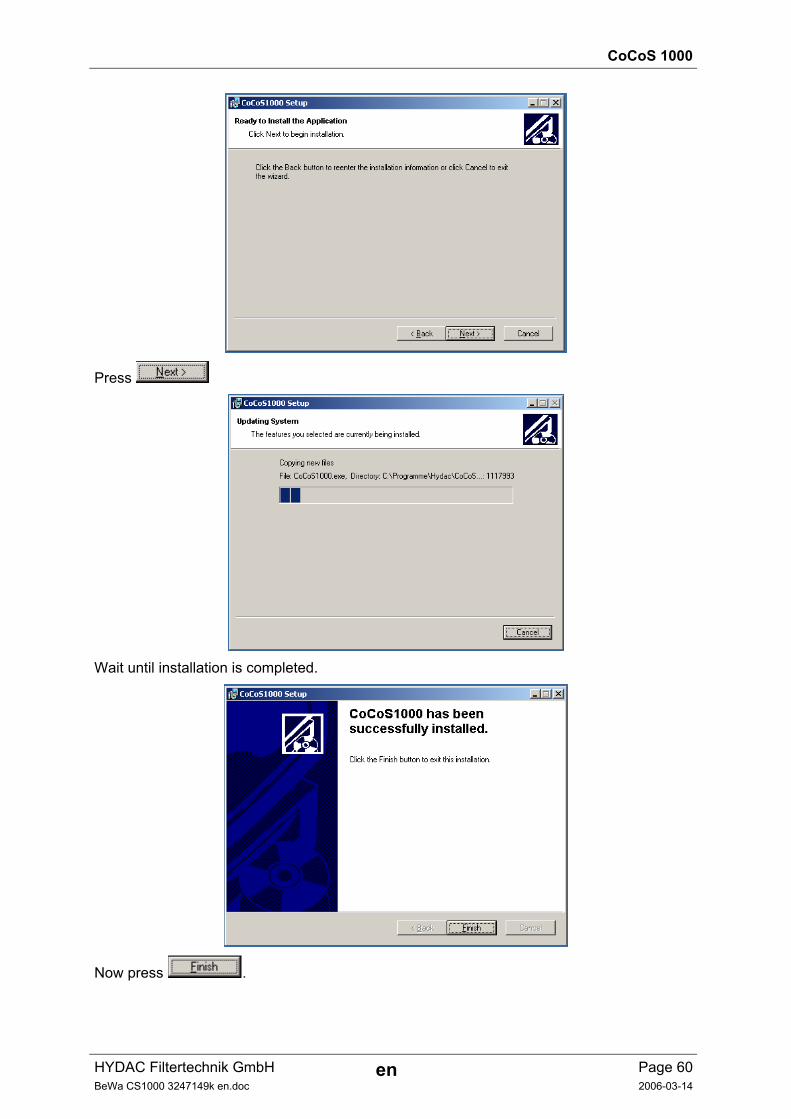
CoCoS 1000
HYDAC Filtertechnik GmbH en Page 60BeWa CS1000 3247149k en.doc 2006-03-14
Press
Wait until installation is completed.
Now press .
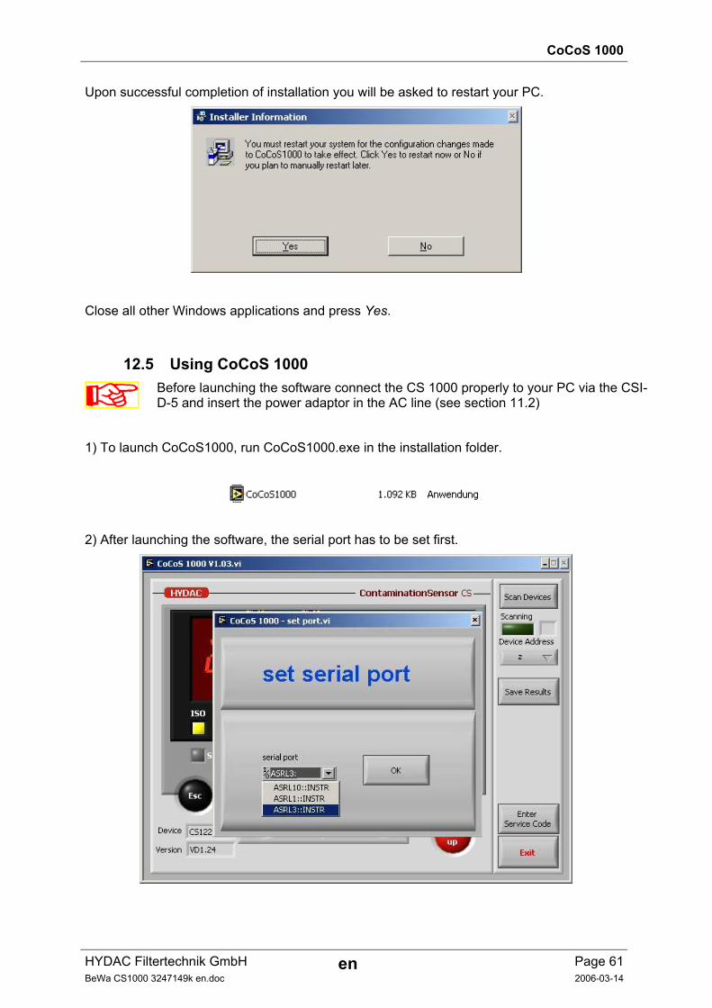
CoCoS 1000
HYDAC Filtertechnik GmbH en Page 61BeWa CS1000 3247149k en.doc 2006-03-14
Upon successful completion of installation you will be asked to restart your PC.
Close all other Windows applications and press Yes.
12.5 Using CoCoS 1000
Before launching the software connect the CS 1000 properly to your PC via the CSI-D-5 and insert the power adaptor in the AC line (see section 11.2)
1) To launch CoCoS1000, run CoCoS1000.exe in the installation folder.
2) After launching the software, the serial port has to be set first.
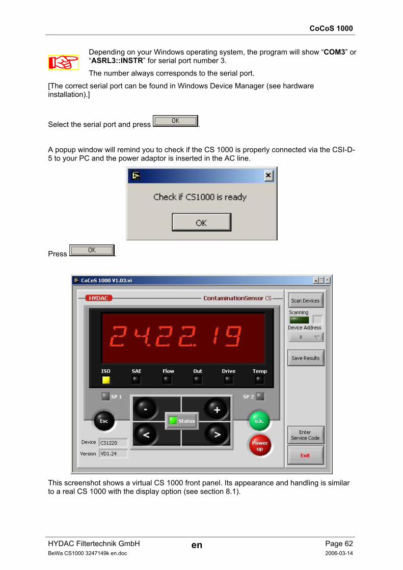
CoCoS 1000
HYDAC Filtertechnik GmbH en Page 62BeWa CS1000 3247149k en.doc 2006-03-14
Depending on your Windows operating system, the program will show “COM3” or “ASRL3::INSTR” for serial port number 3.
The number always corresponds to the serial port.
[The correct serial port can be found in Windows Device Manager (see hardware installation).]
Select the serial port and press .
A popup window will remind you to check if the CS 1000 is properly connected via the CSI-D-5 to your PC and the power adaptor is inserted in the AC line.
Press .
This screenshot shows a virtual CS 1000 front panel. Its appearance and handling is similar to a real CS 1000 with the display option (see section 8.1).
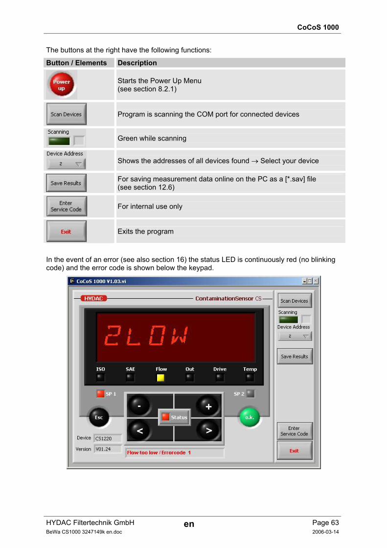
CoCoS 1000
HYDAC Filtertechnik GmbH en Page 63BeWa CS1000 3247149k en.doc 2006-03-14
The buttons at the right have the following functions:
Button / Elements Description
Starts the Power Up Menu (see section 8.2.1)
Program is scanning the COM port for connected devices
Green while scanning
Shows the addresses of all devices found → Select your device
For saving measurement data online on the PC as a [*.sav] file (see section 12.6)
For internal use only
Exits the program
In the event of an error (see also section 16) the status LED is continuously red (no blinking code) and the error code is shown below the keypad.
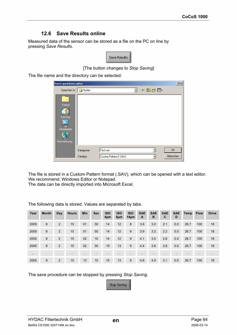
CoCoS 1000
HYDAC Filtertechnik GmbH en Page 64BeWa CS1000 3247149k en.doc 2006-03-14
12.6 Save Results online Measured data of the sensor can be stored as a file on the PC on line by pressing Save Results.
[The button changes to Stop Saving]
The file name and the directory can be selected:
The file is stored in a Custom Pattern format (.SAV), which can be opened with a text editor. We recommend: Windows Editor or Notepad. The data can be directly imported into Microsoft Excel.
The following data is stored. Values are separated by tabs.
Year Month Day Hours Min Sec ISO4µm
ISO6µm
ISO14µm
SAEA
SAEB
SAE C
SAE D
Temp Flow Drive
2005 8 2 15 01 30 14 12 8 3.6 3.0 2.1 0.0 26.7 100 18
2005 8 2 15 01 50 14 12 9 3.9 3.2 2.2 0.0 26.7 100 18
2005 8 2 15 02 10 14 12 9 4.1 3.5 2.6 0.0 26.7 100 18
2005 8 2 15 02 30 15 13 9 4.4 3.8 2.8 0.0 26.7 100 18
... . . .. .. .. .. .. .. .. .. .. .. .. .. ..
2005 8 2 15 13 10 15 13 9 4.6 4.0 3.1 0.0 26.7 100 18
The save procedure can be stopped by pressing Stop Saving.
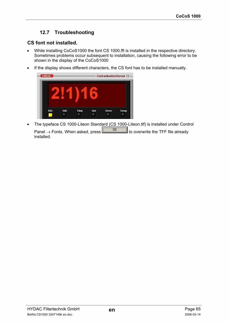
CoCoS 1000
HYDAC Filtertechnik GmbH en Page 65BeWa CS1000 3247149k en.doc 2006-03-14
12.7 Troubleshooting
CS font not installed. • While installing CoCoS1000 the font CS 1000.fft is installed in the respective directory.
Sometimes problems occur subsequent to installation, causing the following error to be shown in the display of the CoCoS1000
• If the display shows different characters, the CS font has to be installed manually.
• The typeface CS 1000-Liteon Standard (CS 1000-Liteon.ttf) is installed under Control
Panel → Fonts. When asked, press to overwrite the TFF file already installed.
Removing, Disposal
HYDAC Filtertechnik GmbH en Page 66BeWa CS1000 3247149k en.doc 2006-02-24
13 Removing the CS from the Hydraulic System 1. Remove electric plug from CS.
2. Remove the hydraulic measurement line from the hydraulic system first, then from the INLET port of the CS.
3. Remove the hydraulic return-flow line from the OUTLET port of the CS.
4. The CS can now be removed.
13.1 Disposal / Recycling and Decommissioning The packing material is to be disposed of as specified by law or national regulations. It can be reused.
When decommissioning and/or disposing of the CS, adherence is to be maintained to local guidelines and regulations pertaining to occupational safety and environmental protection. This applies in particular to the oil in the unit, components covered with oil and electronic components.
After disassembling the unit and separating the various materials, they can be reused or disposed of properly in accordance with local regulations.
14 Spare parts and Accessories
Description Qty. Part no.
Connector with 2 m cable, screened, 8-pole, M12x1 1 3281220
Connector with 5 m cable, screened, 8-pole, M12x1 1 3281239
Extension cable 5 m, socket 8-pole, M12x1 / plug 8-pole, M12x1 1 3281240
Connector 8-pole, M12x1, screened, with screw clamp 1 3281243
CD with - PC-Software package CoCoS 1000 and - Operation and Maintenance Instruction 1 3251484
Contamination Sensor Interface CSI-D-5 1 3249563
O-ring for flange connection model (48x1,78 - 80 Shore FPM) 1 6003048
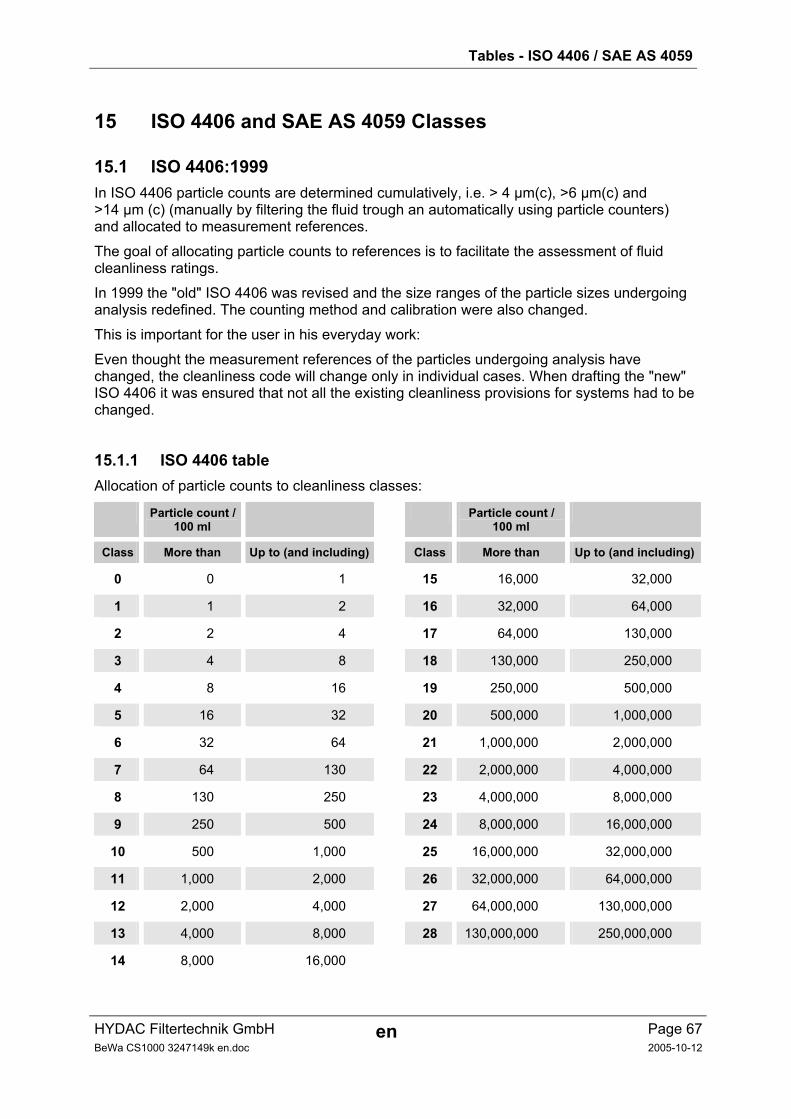
Tables - ISO 4406 / SAE AS 4059
HYDAC Filtertechnik GmbH en Page 67BeWa CS1000 3247149k en.doc 2005-10-12
15 ISO 4406 and SAE AS 4059 Classes
15.1 ISO 4406:1999 In ISO 4406 particle counts are determined cumulatively, i.e. > 4 µm(c), >6 µm(c) and >14 µm (c) (manually by filtering the fluid trough an automatically using particle counters) and allocated to measurement references.
The goal of allocating particle counts to references is to facilitate the assessment of fluid cleanliness ratings.
In 1999 the "old" ISO 4406 was revised and the size ranges of the particle sizes undergoing analysis redefined. The counting method and calibration were also changed.
This is important for the user in his everyday work:
Even thought the measurement references of the particles undergoing analysis have changed, the cleanliness code will change only in individual cases. When drafting the "new" ISO 4406 it was ensured that not all the existing cleanliness provisions for systems had to be changed.
15.1.1 ISO 4406 table Allocation of particle counts to cleanliness classes:
Particle count / 100 ml
Particle count / 100 ml
Class More than Up to (and including) Class More than Up to (and including)
0 0 1 15 16,000 32,000
1 1 2 16 32,000 64,000
2 2 4 17 64,000 130,000
3 4 8 18 130,000 250,000
4 8 16 19 250,000 500,000
5 16 32 20 500,000 1,000,000
6 32 64 21 1,000,000 2,000,000
7 64 130 22 2,000,000 4,000,000
8 130 250 23 4,000,000 8,000,000
9 250 500 24 8,000,000 16,000,000
10 500 1,000 25 16,000,000 32,000,000
11 1,000 2,000 26 32,000,000 64,000,000
12 2,000 4,000 27 64,000,000 130,000,000
13 4,000 8,000 28 130,000,000 250,000,000
14 8,000 16,000
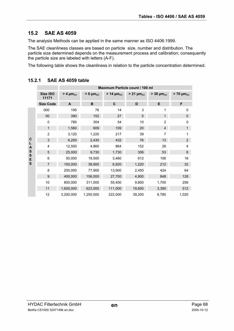
Tables - ISO 4406 / SAE AS 4059
HYDAC Filtertechnik GmbH en Page 68BeWa CS1000 3247149k en.doc 2005-10-12
15.2 SAE AS 4059 The analysis Methods can be applied in the same manner as ISO 4406:1999.
The SAE cleanliness classes are based on particle size, number and distribution. The particle size determined depends on the measurement process and calibration; consequently the particle size are labeled with letters (A-F).
The following table shows the cleanliness in relation to the particle concentration determined.
15.2.1 SAE AS 4059 table Maximum Particle count / 100 ml
Size ISO 11171
> 4 µm(c) > 6 µm(c) > 14 µm(c) > 21 µm(c) > 38 µm(c) > 70 µm(c)
Size Code A B C D E F 000 195 76 14 3 1 0
00 390 152 27 5 1 0
0 780 304 54 10 2 0
1 1,560 609 109 20 4 1
2 3,120 1,220 217 39 7 1
3 6,250 2,430 432 76 13 2
4 12,500 4,860 864 152 26 4
5 25,000 9,730 1,730 306 53 8
6 50,000 19,500 3,460 612 106 16
7 100,000 38,900 6,920 1,220 212 32
8 200,000 77,900 13,900 2,450 424 64
9 400,000 156,000 27,700 4,900 848 128
10 800,000 311,000 55,400 9,800 1,700 256
11 1,600,000 623,000 111,000 19,600 3,390 512
CLASSES
12 3,200,000 1,250,000 222,000 39,200 6,780 1,020
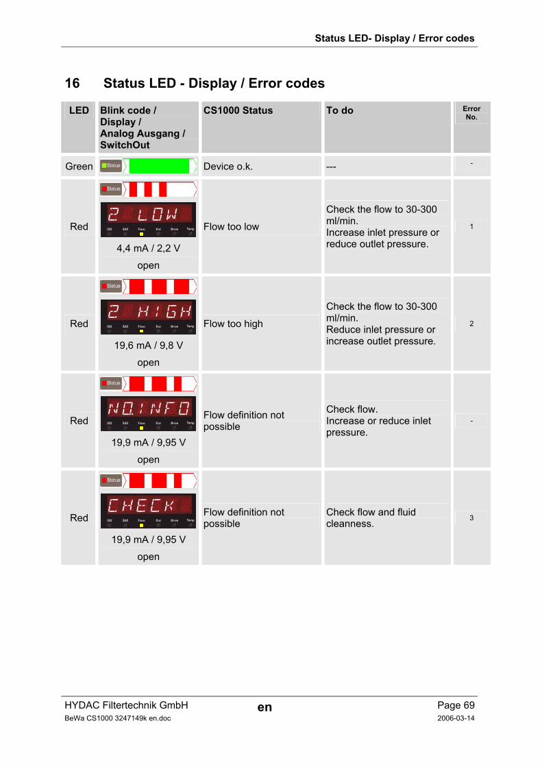
Status LED- Display / Error codes
HYDAC Filtertechnik GmbH en Page 69BeWa CS1000 3247149k en.doc 2006-03-14
16 Status LED - Display / Error codes
LED Blink code / Display / Analog Ausgang / SwitchOut
CS1000 Status To do Error No.
Green Device o.k. --- -
Red
2 LOW
4,4 mA / 2,2 V
open
Flow too low
Check the flow to 30-300 ml/min. Increase inlet pressure or reduce outlet pressure.
1
Red
2 HIGH
19,6 mA / 9,8 V
open
Flow too high
Check the flow to 30-300 ml/min. Reduce inlet pressure or increase outlet pressure.
2
Red
NoINFO
19,9 mA / 9,95 V
open
Flow definition not possible
Check flow. Increase or reduce inlet pressure.
-
Red
CHECK
19,9 mA / 9,95 V
open
Flow definition not possible
Check flow and fluid cleanness.
3
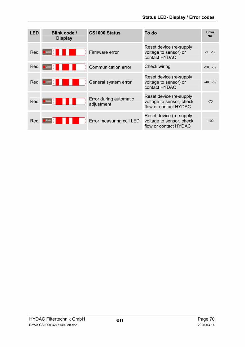
Status LED- Display / Error codes
HYDAC Filtertechnik GmbH en Page 70BeWa CS1000 3247149k en.doc 2006-03-14
LED Blink code / Display
CS1000 Status To do Error No.
Red Firmware error Reset device (re-supply voltage to sensor) or contact HYDAC
-1...-19
Red Communication error Check wiring -20...-39
Red General system error Reset device (re-supply voltage to sensor) or contact HYDAC
-40...-69
Red Error during automatic adjustment
Reset device (re-supply voltage to sensor, check flow or contact HYDAC
-70
Red Error measuring cell LED Reset device (re-supply voltage to sensor, check flow or contact HYDAC
-100
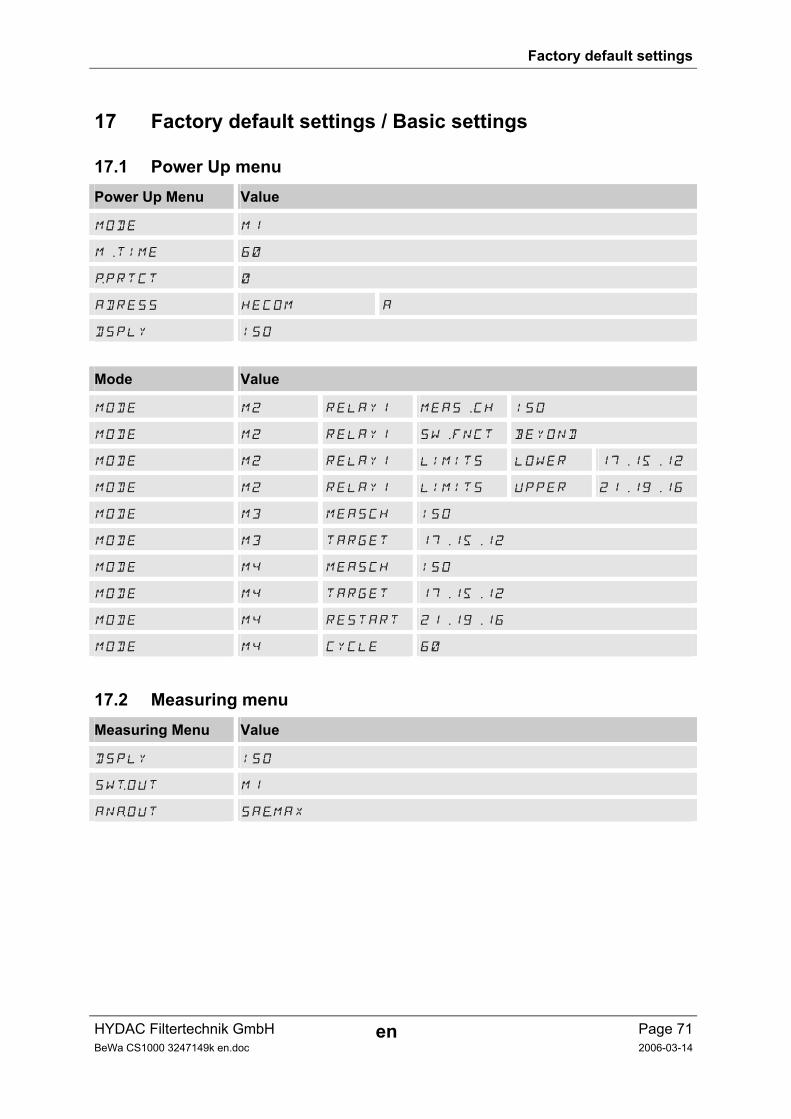
Factory default settings
HYDAC Filtertechnik GmbH en Page 71BeWa CS1000 3247149k en.doc 2006-03-14
17 Factory default settings / Basic settings
17.1 Power Up menu Power Up Menu Value
MODE M1
M.TIME 60
pPRTCT 0
ADRESS HECOM A
DSPLY ISO
Mode Value
MODE M2 RELAY1 MEAS.CH ISO
MODE M2 RELAY1 SW.FNCT BEYOND
MODE M2 RELAY1 LIMITS LOWER 17.15.12
MODE M2 RELAY1 LIMITS UPPER 21.19.16
MODE M3 MEASCH ISO
MODE M3 TARGET 17.15.12
MODE M4 MEASCH ISO
MODE M4 TARGET 17.15.12
MODE M4 RESTART 21.19.16
MODE M4 CYCLE 60
17.2 Measuring menu Measuring Menu Value
DSPLY ISO
SWtOUT M1
ANaOUT SAeMAX
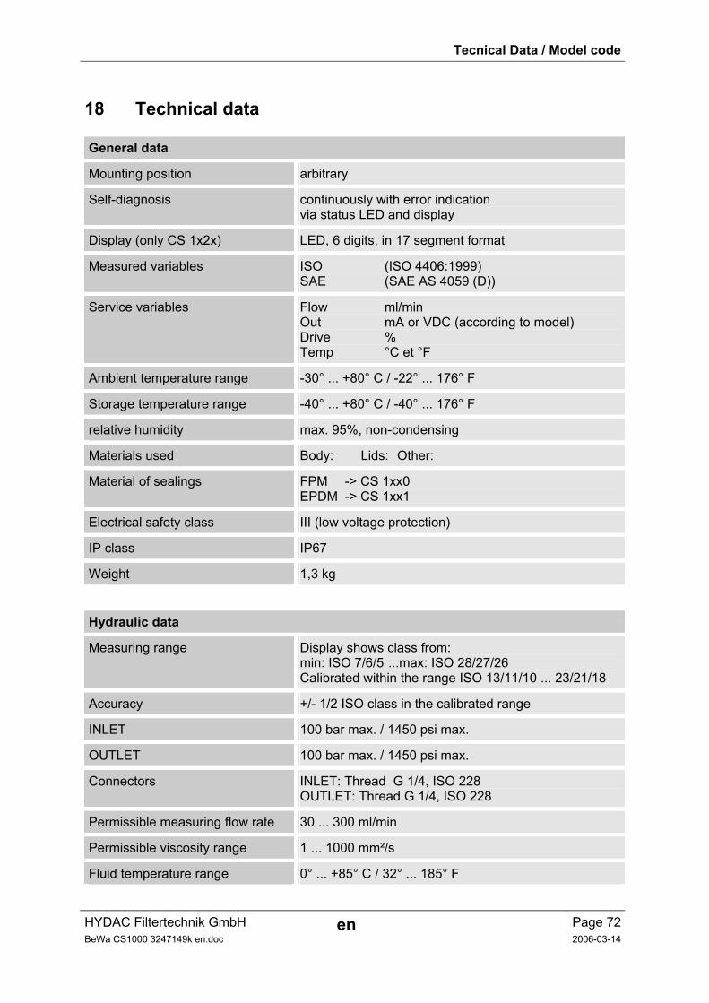
Tecnical Data / Model code
HYDAC Filtertechnik GmbH en Page 72BeWa CS1000 3247149k en.doc 2006-03-14
18 Technical data
General data
Mounting position arbitrary
Self-diagnosis continuously with error indication via status LED and display
Display (only CS 1x2x) LED, 6 digits, in 17 segment format
Measured variables ISO (ISO 4406:1999) SAE (SAE AS 4059 (D))
Service variables Flow ml/min Out mA or VDC (according to model) Drive % Temp °C et °F
Ambient temperature range -30° ... +80° C / -22° ... 176° F
Storage temperature range -40° ... +80° C / -40° ... 176° F
relative humidity max. 95%, non-condensing
Materials used Body: Lids: Other:
Material of sealings FPM -> CS 1xx0 EPDM -> CS 1xx1
Electrical safety class III (low voltage protection)
IP class IP67
Weight 1,3 kg
Hydraulic data
Measuring range Display shows class from: min: ISO 7/6/5 ...max: ISO 28/27/26 Calibrated within the range ISO 13/11/10 ... 23/21/18
Accuracy +/- 1/2 ISO class in the calibrated range
INLET 100 bar max. / 1450 psi max.
OUTLET 100 bar max. / 1450 psi max.
Connectors INLET: Thread G 1/4, ISO 228 OUTLET: Thread G 1/4, ISO 228
Permissible measuring flow rate 30 ... 300 ml/min
Permissible viscosity range 1 ... 1000 mm²/s
Fluid temperature range 0° ... +85° C / 32° ... 185° F
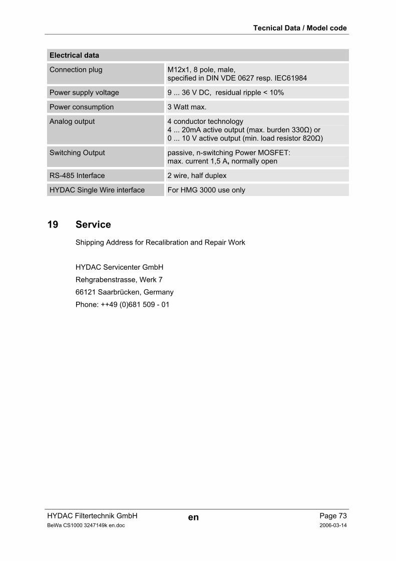
Tecnical Data / Model code
HYDAC Filtertechnik GmbH en Page 73BeWa CS1000 3247149k en.doc 2006-03-14
Electrical data
Connection plug M12x1, 8 pole, male, specified in DIN VDE 0627 resp. IEC61984
Power supply voltage 9 ... 36 V DC, residual ripple < 10%
Power consumption 3 Watt max.
Analog output 4 conductor technology 4 ... 20mA active output (max. burden 330Ω) or 0 ... 10 V active output (min. load resistor 820Ω)
Switching Output passive, n-switching Power MOSFET: max. current 1,5 A, normally open
RS-485 Interface 2 wire, half duplex
HYDAC Single Wire interface For HMG 3000 use only
19 Service Shipping Address for Recalibration and Repair Work
HYDAC Servicenter GmbH
Rehgrabenstrasse, Werk 7
66121 Saarbrücken, Germany
Phone: ++49 (0)681 509 - 01
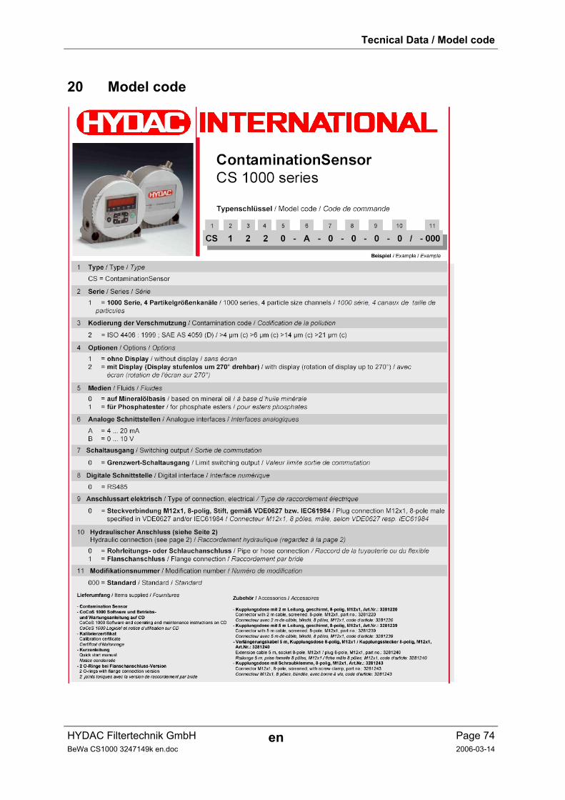
Tecnical Data / Model code
HYDAC Filtertechnik GmbH en Page 74BeWa CS1000 3247149k en.doc 2006-03-14
20 Model code