CARBODURCARBODUR
CARBODUR
Engineer ing steels
Case-hardening steels
EDELSTAHL WITTEN-KREFELD GMBH
CARBODURCARBODUR
CARBODUR


3
Contents
Page 4 – 7 Carbodur – The material
Page 8 – 9 Energy industry
Page 10 – 11 Transport
Page 12 – 13 General mechanical engineering
Page 14 – 15 Steel portraits
Page 16 – 17 Steel production
Page 18 – 19 Steel processing
Material data
Page 20 – 31 Material Data Sheets
(Please note the text on the flap of the rear cover, which contains
information on the Material Data Sheets)
Technical information
Page 32 – 36 Hardenability
Page 37 – 39 Machining and heat treatment
Page 40 – 43 Case-hardening treatment
Page 44 Overview of grades and chemical composition
Page 45 Melt analysis/International standards
Page 46 Forms supplied
Page 47 Hardness comparison table
Page 48 Temperature Comparison
Page 50 List of photos
How long a component stands up
to demands, and how reliably it
withstands peak stresses, de-
pends on the material the compo-
nent is made of. In the final analy-
sis, the load-bearing capacity of a
small part determines the cost-
efficiency of large machines or
installations.
The more carefully the material is
tailored to the function of the re-
spective components, the more
efficient the entire system is.
Edelstahl Witten-Krefeld is the
specialist for producing high-
grade steels with highly specific,
precisely defined properties.
The group of case-hardening
steels marketed under the brand
name Carbodur is evidence of the
leading international position of
Edelstahl Witten-Krefeld in the
field of high-strength, high-grade
steels.
The case-hardening steels pre-
sented in this brochure are un-
alloyed and alloyed special
engineering steels with relatively
low carbon contents of roughly
0.10 to 0.25%.
4
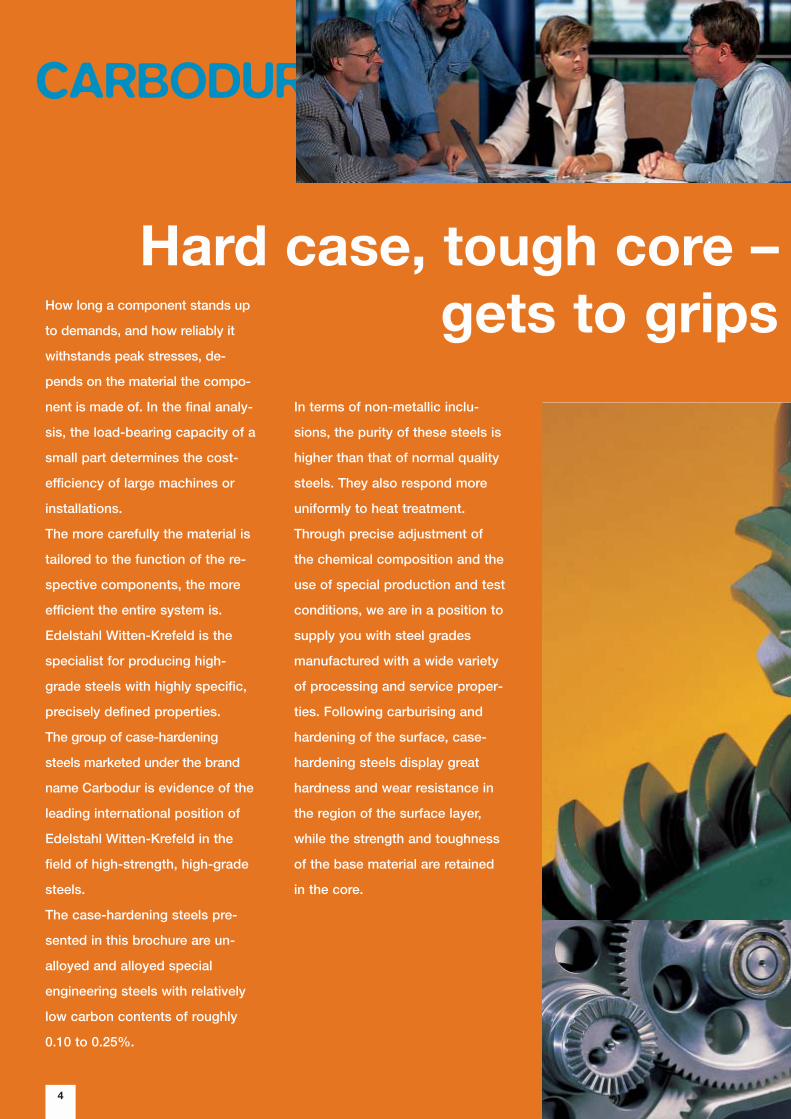
In terms of non-metallic inclu-
sions, the purity of these steels is
higher than that of normal quality
steels. They also respond more
uniformly to heat treatment.
Through precise adjustment of
the chemical composition and the
use of special production and test
conditions, we are in a position to
supply you with steel grades
manufactured with a wide variety
of processing and service proper-
ties. Following carburising and
hardening of the surface, case-
hardening steels display great
hardness and wear resistance in
the region of the surface layer,
while the strength and toughness
of the base material are retained
in the core.
CARBODUR
Hard case, tough core –gets to grips
5
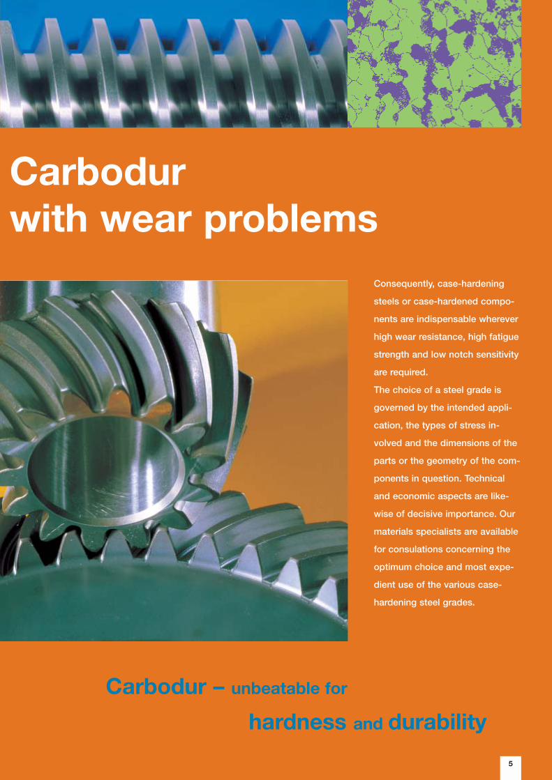
Consequently, case-hardening
steels or case-hardened compo-
nents are indispensable wherever
high wear resistance, high fatigue
strength and low notch sensitivity
are required.
The choice of a steel grade is
governed by the intended appli-
cation, the types of stress in-
volved and the dimensions of the
parts or the geometry of the com-
ponents in question. Technical
and economic aspects are like-
wise of decisive importance. Our
materials specialists are available
for consulations concerning the
optimum choice and most expe-
dient use of the various case-
hardening steel grades.
Carbodur – unbeatable for
hardness and durability
Carbodurwith wear problems
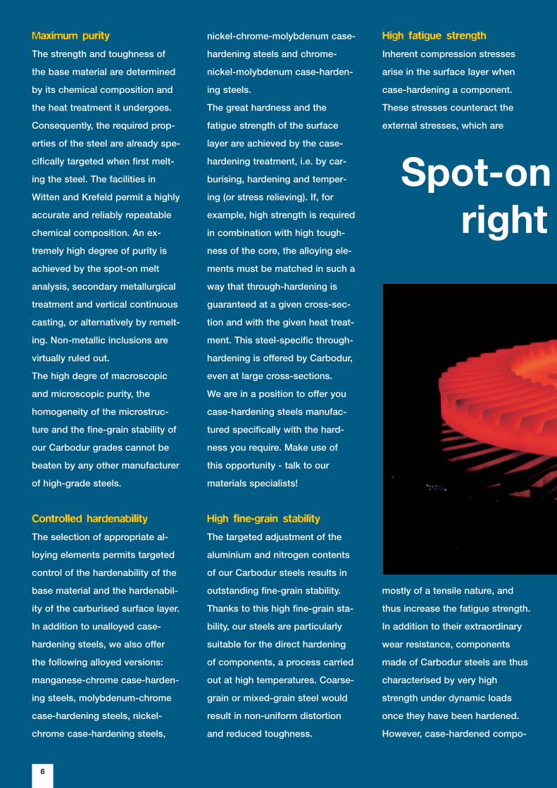
mostly of a tensile nature, and
thus increase the fatigue strength.
In addition to their extraordinary
wear resistance, components
made of Carbodur steels are thus
characterised by very high
strength under dynamic loads
once they have been hardened.
However, case-hardened compo-
Maximum purity
The strength and toughness of
the base material are determined
by its chemical composition and
the heat treatment it undergoes.
Consequently, the required prop-
erties of the steel are already spe-
cifically targeted when first melt-
ing the steel. The facilities in
Witten and Krefeld permit a highly
accurate and reliably repeatable
chemical composition. An ex-
tremely high degree of purity is
achieved by the spot-on melt
analysis, secondary metallurgical
treatment and vertical continuous
casting, or alternatively by remelt-
ing. Non-metallic inclusions are
virtually ruled out.
The high degre of macroscopic
and microscopic purity, the
homogeneity of the microstruc-
ture and the fine-grain stability of
our Carbodur grades cannot be
beaten by any other manufacturer
of high-grade steels.
Controlled hardenability
The selection of appropriate al-
loying elements permits targeted
control of the hardenability of the
base material and the hardenabil-
ity of the carburised surface layer.
In addition to unalloyed case-
hardening steels, we also offer
the following alloyed versions:
manganese-chrome case-harden-
ing steels, molybdenum-chrome
case-hardening steels, nickel-
chrome case-hardening steels,
6
nickel-chrome-molybdenum case-
hardening steels and chrome-
nickel-molybdenum case-harden-
ing steels.
The great hardness and the
fatigue strength of the surface
layer are achieved by the case-
hardening treatment, i.e. by car-
burising, hardening and temper-
ing (or stress relieving). If, for
example, high strength is required
in combination with high tough-
ness of the core, the alloying ele-
ments must be matched in such a
way that through-hardening is
guaranteed at a given cross-sec-
tion and with the given heat treat-
ment. This steel-specific through-
hardening is offered by Carbodur,
even at large cross-sections.
We are in a position to offer you
case-hardening steels manufac-
tured specifically with the hard-
ness you require. Make use of
this opportunity - talk to our
materials specialists!
High fine-grain stability
The targeted adjustment of the
aluminium and nitrogen contents
of our Carbodur steels results in
outstanding fine-grain stability.
Thanks to this high fine-grain sta-
bility, our steels are particularly
suitable for the direct hardening
of components, a process carried
out at high temperatures. Coarse-
grain or mixed-grain steel would
result in non-uniform distortion
and reduced toughness.
Spot-on right
High fatigue strength
Inherent compression stresses
arise in the surface layer when
case-hardening a component.
These stresses counteract the
external stresses, which are

7
– Carbodur has just thechemstry for you
nents also have to demonstrate
the highest possible ductility
when exposed to high dynamic
stresses, in order to avoid brittle
fractures. As the impact strength
of the component decreases with
increasing case-hardening depth,
the latter must not be too great.
Good machinability
The larger the quantity of compo-
nents to be manufactured, the
more important the demand for
good machinability of the materi-
al. This means that the economic
efficiency of series production is
already defined when ordering the
steel. The machinability of case-
hardening steels is influenced by
the microstructure, the strength
and the non-metallic inclusions
(sulphides, oxides) that may be
present. The machinability of the
steel can be further optimised by
increasing the amount of sulphid-
ic inclusions, by calcium treat-
ment and by appropriate heat
treatment, i.e. by specifically ad-
justing the microstructure.
Made-to-measure heat
treatment
Depending on the intended appli-
cation and processing, we can
supply you with Carbodur steel
grades in a wide variety of treated
conditions, e.g. with reduced
hardness, maximum hardness or
a specific hardness range, treated
for ferrite-pearlite structure or for
spherical carbides.
Detailed technical information on
forms supplied and machining
can be found from Page 32
onwards.
8
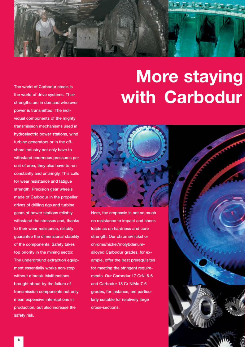
More staying with Carbodur
The world of Carbodur steels is
the world of drive systems. Their
strengths are in demand wherever
power is transmitted. The indi-
vidual components of the mighty
transmission mechanisms used in
hydroelectric power stations, wind
turbine generators or in the off-
shore industry not only have to
withstand enormous pressures per
unit of area, they also have to run
constantly and untiringly. This calls
for wear resistance and fatigue
strength. Precision gear wheels
made of Carbodur in the propeller
drives of drilling rigs and turbine
gears of power stations reliably
withstand the stresses and, thanks
to their wear resistance, reliably
guarantee the dimensional stability
of the components. Safety takes
top priority in the mining sector.
The underground extraction equip-
ment essentially works non-stop
without a break. Malfunctions
brought about by the failure of
transmission components not only
mean expensive interruptions in
production, but also increase the
safety risk.
Here, the emphasis is not so much
on resistance to impact and shock
loads as on hardness and core
strength. Our chrome/nickel or
chrome/nickel/molybdenum-
alloyed Carbodur grades, for ex-
ample, offer the best prerequisites
for meeting the stringent require-
ments. Our Carbodur 17 CrNi 6-6
and Carbodur 18 Cr NiMo 7-6
grades, for instance, are particu-
larly suitable for relatively large
cross-sections.
9
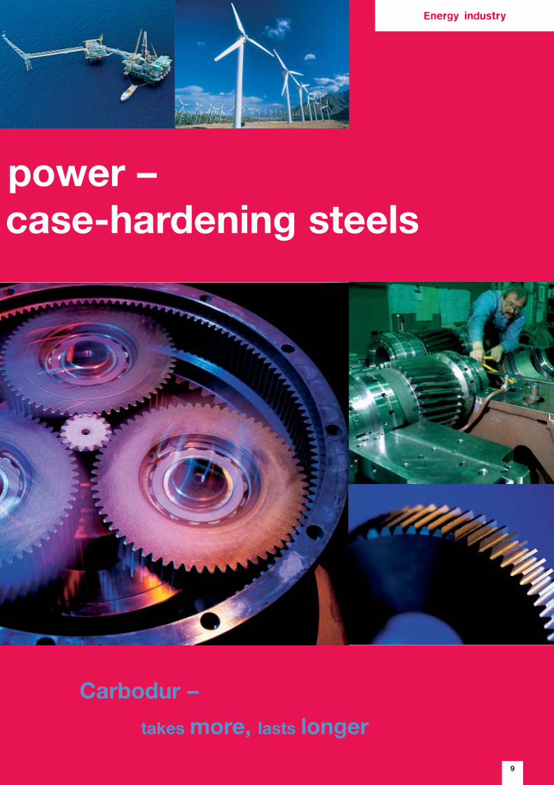
power – case-hardening steels
Carbodur –
takes more, lasts longer
Energy industry

10
Carbodur – the winnercomes
Just as there is a wide variety of
demands on the components for
different types of vehicle, we also
have a wide variety of options for
precisely adapting our Carbodur
steels to suit the prevaillign re-
quirements. The suitable material
for the components is selected
with a view to safety, economic
efficiency and a long service life,
or the ability to withstand extreme
stresses for short periods.
The differential of a Formula 1 car,
for example, only has to withstand
stress for a relatively short time -
the duration of a race (at least!).
On the other hand, it is exposed to
extreme stresses for short periods
of time as a result of the enormous
torques transmitted. Carbodur
steel can be specifically “tuned” to
cope with this task.
In contrast, the gear wheels of a
truck that works under the tough
conditions of a building site have
to take constant punishment over
long periods, and must also be
capable of absorbing sudden
blows and shocks without losing
any teeth. The case-hardened
parts have to display a combina-
tion of wear resistance and fatigue
strength in the surface layer and
impact strength in the core zone.
Safety takes top priority in the
passenger transport sector. Con-
sequently, the specific properties
of Carbodur steels are particularly
advantageous for engines and
gearboxes in automotive engi-
neering. They can be used, for
example, in piston pins, speed
change gears, drive shafts, coun-
tershafts, synchroniser bodies,
ring gears, differential bevel gears,
bevel pinions and differential side
gears.
11
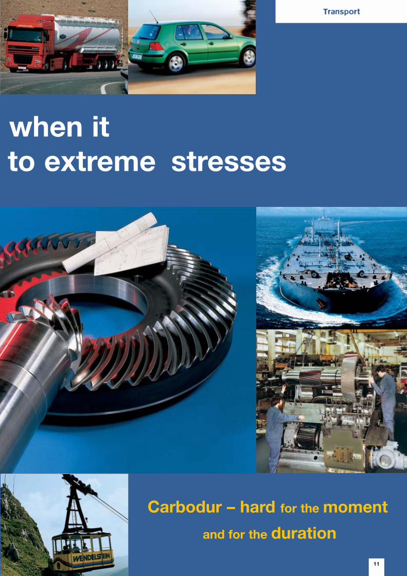
when itto extreme stresses
Carbodur – hard for the moment
and for the duration
Transport
12
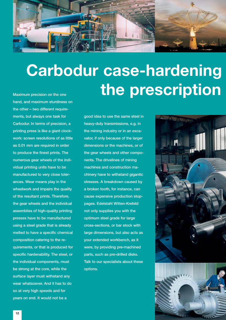
Carbodur case-hardening the prescription Maximum precision on the one
hand, and maximum sturdiness on
the other – two different require-
ments, but always one task for
Carbodur. In terms of precision, a
printing press is like a giant clock-
work: screen resolutions of as little
as 0.01 mm are required in order
to produce the finest prints. The
numerous gear wheels of the indi-
vidual printing units have to be
manufactured to very close toler-
ances. Wear means play in the
wheelwork and impairs the quality
of the resultant prints. Therefore,
the gear wheels and the individual
assemblies of high-quality printing
presses have to be manufactured
using a steel grade that is already
melted to have a specific chemical
composition catering to the re-
quirements, or that is produced for
specific hardenability. The steel, or
the individual components, must
be strong at the core, while the
surface layer must withstand any
wear whatsoever. And it has to do
so at very high speeds and for
years on end. It would not be a
good idea to use the same steel in
heavy-duty transmissions, e.g. in
the mining industry or in an exca-
vator, if only because of the larger
dimensions or the machines, or of
the gear wheels and other compo-
nents. The drivelines of mining
machines and construction ma-
chinery have to withstand gigantic
stresses. A breakdown caused by
a broken tooth, for instance, can
cause expensive production stop-
pages. Edelstahl Witten-Krefeld
not only supplies you with the
optimum steel grade for large
cross-sections, or bar stock with
large dimensions, but also acts as
your extended workbench, as it
were, by providing pre-machined
parts, such as pre-drilled disks.
Talk to our specialists about these
options.
und
13
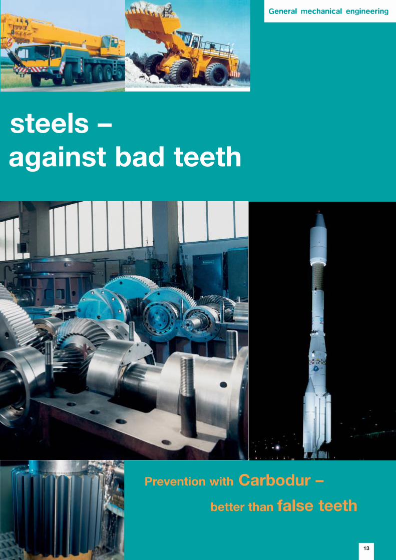
steels – against bad teeth
Carbodur – für den Moment
d auf Dauer
Prevention with Carbodur –
better than false teeth
General mechanical engineering
14
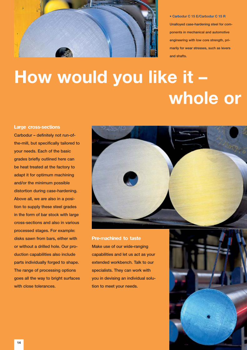
How would you like it – whole or
Large cross-sections
Carbodur – definitely not run-of-
the-mill, but specifically tailored to
your needs. Each of the basic
grades briefly outlined here can
be heat treated at the factory to
adapt it for optimum machining
and/or the minimum possible
distortion during case-hardening.
Above all, we are also in a posi-
tion to supply these steel grades
in the form of bar stock with large
cross-sections and also in various
processed stages. For example:
disks sawn from bars, either with
or without a drilled hole. Our pro-
duction capabilities also include
parts individually forged to shape.
The range of processing options
goes all the way to bright surfaces
with close tolerances.
Pre-machined to taste
Make use of our wide-ranging
capabilities and let us act as your
extended workbench. Talk to our
specialists. They can work with
you in devising an individual solu-
tion to meet your needs.
• Carbodur C 15 E/Carbodur C 15 R
Unalloyed case-hardening steel for com-
ponents in mechanical and automotive
engineering with low core strength, pri-
marily for wear stresses, such as levers
and shafts.

15
sliced?
Carbodur – metallurgical
delicacies à la carte
• Carbodur 16 MnCr 5
• Carbodur 16 MnCrS 5
CrMn-alloyed case-hardening steel for
components in mechanical and automotive
engineering with relatively high core
strength, e.g. relatively large piston pins,
camshafts and gear wheels
• Carbodur 15 NiCr 13
NiCr-alloyed case-hardening steel for highly
stressed components in mechanical engi-
neering with high demands on toughness
at low temperatures.
• Carbodur 17 Cr 3
Cr-alloyed case-hardening steel for compo-
nents in mechanical and automotive engi-
neering with low core strength, primarily for
wear stressed, e.g. piston pins and cam-
shafts
• Carbodur 17 CrNi 6-6
CrNi-alloyed case-hardening steel for high-
ly stressed components in mechanical and
automotive engineering with high strength
and toughness at relatively large cross-
sections, such as bevel pinions, pinion
gears, shafts, pins and countershafts
• Carbodur 18 CrNi 8
CrNi-alloyed case-hardening steel for high-
ly stressed components in mechanical and
automotive engineering with very high
strength and toughness at relatively large
cross-sections, such as bevel pinions, pin-
ion gears, shafts, pins and countershafts
• Carbodur 18 CrNiMo 7-6
CrNiMo-alloyed case-hardening steel for
heavy-duty and highly stressed transmis-
sion components in mechanical engineer-
ing with high demands on toughness, e.g.
gear wheels, pinion gears and worm shafts
• Carbodur 20 NiMoCrS 6-5
NiMoCr-alloyed case-hardening steel for
highly stressed components in mechanical
and automotive engineering with high strength
and toughness, e.g. bevel pinions, pinion
gears, shafts, pins and countershafts
• Carbodur 20 MnCr 5
• Carbodur 20 MnCrS 5
CrMn-alloyed case-hardening steel for
components in mechanical and automotive
engineering with relatively high core strength,
e.g. gear wheels, ring gears, main shafts
and countershafts
• Carbodur 20 MoCr 4
• Carbodur 20 MoCrS 4
MoCr-alloyed case-hardening steels for
components in mechanical and automotive
engineering with relatively high core strength,
e.g. gear wheels, ring gears, main shafts
and countershafts
• Carbodur 20 NiCrMo 2-2
• Carbodur 20 NiCrMoS 2-2
NiCrMo-alloyed case-hardening steel for
components in mechanical and automotive
engineering with relatively high core strength,
e.g. gear wheels, spiders and ball cages
• Carbodur 22 CrMoS 3-5
CrMo-alloyed case-hardening steel for
components in mechanical and automotive
engineering with relatively high core strength,
e.g. gear wheels, ring gears, shafts and
spiders
Steel portraits
16
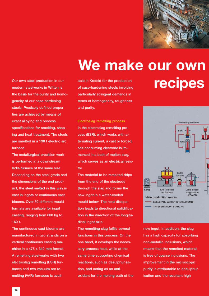
We make our own recipes Our own steel production in our
modern steelworks in Witten is
the basis for the purity and homo-
geneity of our case-hardening
steels. Precisely defined proper-
ties are achieved by means of
exact alloying and process
specifications for smelting, shap-
ing and heat treatment. The steels
are smelted in a 130 t electric arc
furnace.
The metallurgical precision work
is performed in a downstream
ladle furnace of the same size.
Depending on the steel grade and
the dimensions of the end prod-
uct, the steel melted in this way is
cast in ingots or continuous cast
blooms. Over 50 different mould
formats are available for ingot
casting, ranging from 600 kg to
160 t.
The continuous cast blooms are
manufactured in two strands on a
vertical continuous casting ma-
chine in a 475 x 340 mm format.
A remelting steelworks with two
electroslag remelting (ESR) fur-
naces and two vacuum arc re-
melting (VAR) furnaces is avail-
new ingot. In addition, the slag
has a high capacity for absorbing
non-metallic inclusions, which
means that the remelted material
is free of coarse inclusions. The
improvement in the microscopic
purity is attributable to desulphur-
isation and the resultant high
able in Krefeld for the production
of case-hardening steels involving
particularly stringent demands in
terms of homogeneity, toughness
and purity.
Electroslag remelting process
In the electroslag remelting pro-
cess (ESR), which works with al-
ternating current, a cast or forged,
self-consuming electrode is im-
mersed in a bath of molten slag,
which serves as an electrical resis-
tor.
The material to be remelted drips
from the end of the electrode
through the slag and forms the
new ingot in a water-cooled
mould below. The heat dissipa-
tion leads to directional solidifica-
tion in the direction of the longitu-
dinal ingot axis.
The remelting slag fulfils several
functions in this process. On the
one hand, it develops the neces-
sary process heat, while at the
same time supporting chemical
reactions, such as desulphurisa-
tion, and acting as an anti-
oxidant for the melting bath of the
Scrap 130-t-electricarc furnace
Ladle degas-sing station(VD/VOD)
Remelting facilities
ESR
VAR
EDELSTAHL WITTEN-KREFELD GMBH
THYSSEN KRUPP STAHL AG
Main production routes
Ladlefurnace
17
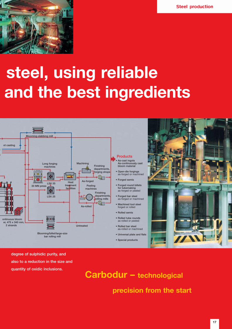
steel, using reliableand the best ingredients
degree of sulphidic purity, and
also to a reduction in the size and
quantity of oxidic inclusions.
Carbodur – technological
precision from the start
Steel production
ontinuous bloomer, 475 x 340 mm,
2 strands
Blooming/billet/large-sizebar rolling mill
Untreated
As-rolled
LSX 25
33 MN pressLSX 55
Long forging machines
As-forged
Finishingdepartments,rolling mills
Finishingdepartments,forging shops
Heattreatmentfacilities
Blooming-slabbing mill
ot casting
Machining
Products
Peelingmachines
• As-cast ingots As-continuously cast bloom material
• Open-die forgingsas-forged or machined
• Forged semis
• Forged round billets for tubemakingas-forged or peeled
• Forged bar steelas-forged or machined
• Machined tool steelforged or rolled
• Rolled semis
• Rolled tube roundsas-rolled or peeled
• Rolled bar steelas-rolled or machined
• Universal plate and flats
• Special products
18
Carbodurtailored to suit
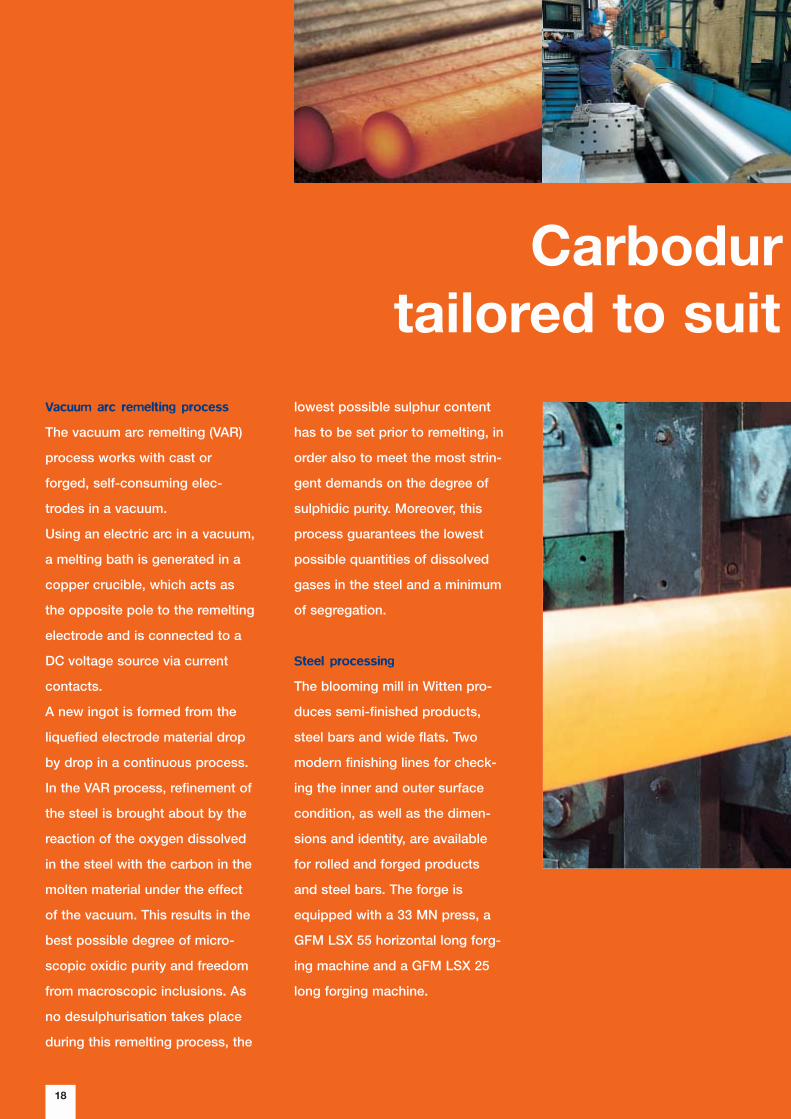
Vacuum arc remelting process
The vacuum arc remelting (VAR)
process works with cast or
forged, self-consuming elec-
trodes in a vacuum.
Using an electric arc in a vacuum,
a melting bath is generated in a
copper crucible, which acts as
the opposite pole to the remelting
electrode and is connected to a
DC voltage source via current
contacts.
A new ingot is formed from the
liquefied electrode material drop
by drop in a continuous process.
In the VAR process, refinement of
the steel is brought about by the
reaction of the oxygen dissolved
in the steel with the carbon in the
molten material under the effect
of the vacuum. This results in the
best possible degree of micro-
scopic oxidic purity and freedom
from macroscopic inclusions. As
no desulphurisation takes place
during this remelting process, the
lowest possible sulphur content
has to be set prior to remelting, in
order also to meet the most strin-
gent demands on the degree of
sulphidic purity. Moreover, this
process guarantees the lowest
possible quantities of dissolved
gases in the steel and a minimum
of segregation.
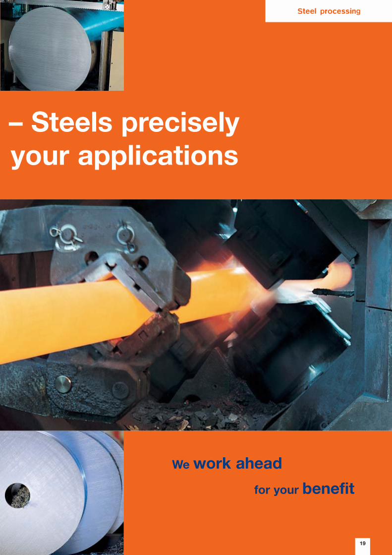
Steel processing
The blooming mill in Witten pro-
duces semi-finished products,
steel bars and wide flats. Two
modern finishing lines for check-
ing the inner and outer surface
condition, as well as the dimen-
sions and identity, are available
for rolled and forged products
and steel bars. The forge is
equipped with a 33 MN press, a
GFM LSX 55 horizontal long forg-
ing machine and a GFM LSX 25
long forging machine.
19
– Steels preciselyyour applications
We work ahead
for your benefit
Steel processing
Cooling
Water (oil),
Hot bath 160 � 250 °C, case-hardening box, air 4)
Water (oil), hot bath 160 � 250 °C 4)
Water (oil), hot bath 160 � 250 °C 4)
Water (oil), hot bath 160 � 250 °C 4)
Air
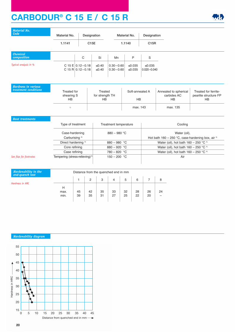
1
4539
2
4235
3
3531
4
3327
5
3225
6
2822
7
2620
8
24�
Type of treatment
Case-hardening
Carburising 2)
Direct hardening 3)
Core refining
Case refining
Tempering (stress-relieving) 5)
CARBODUR® C 15 E / C 15 R
C
0.12�0.180.12�0.18
Si
≤0.40≤0.40
Mn
0.30�0.600.30�0.60
P
≤0.035≤0.035
S
≤0.0350.020�0.040
C 15 EC 15 R
Material No.Code
Chemicalcomposition
Heat treatments
Typical analysis in %
Hmax.min.
Treated forshearing S
HB
1)
Material No.
1.1141
Designation
C15E
Material No.
1.1140
Designation
C15R
Treatedfor strength TH
HB
Soft-annealed A
HB
max. 143
Treated for ferrite-pearlite structure FP
HB
Annealed to sphericalcarbides AC
HB
max. 135
Treatment temperature
880 � 980 °C
880 � 980 °C
880 � 920 °C
780 � 820 °C
150 � 200 °C
Hardness in varioustreatment conditions
Hardenability in theend-quench test
Hardness in HRC
Hardenability diagram
55
50
45
40
35
30
25
20
150 5 10 15 20 25 30 35 40 45
Abstand von der abgeschreckten Stirnfläche in mm
Här
te in
HR
C
Distance from the quenched end in mm
See flap for footnotes
20
Har
dne
ss in
HR
C
Distance from quenched end in mm
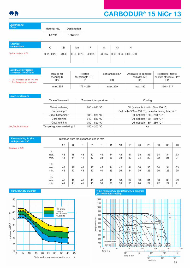
Cooling
Oil (water), hot bath 160 � 250 °C,
Salt bath (580 � 650 °C), case-hardening box, air 4)
Oil, hot bath 160 � 250 °C 4)
Oil, hot bath 160 � 250 °C 4)
Oil, hot bath 160 � 250 °C 4)
Air
Type of treatment
Case-hardening
Carburising 2)
Direct hardening 3)
Core refining
Case refining
Tempering (stress-relieving) 5)
C
0.14�0.20
Si
≤ 0.40
Mn
0.40�0.70
P
≤0.035
S
≤0.035
Cr
0.60�0.90
Ni
3.60�3.50
Material No.Code
Chemicalcomposition
1.5
4841
4843
4641
3
4841
4843
4641
5
4841
4843
4641
7
4740
4742
4540
9
4538
4540
4338
11
4436
4439
4136
13
4233
4236
3833
15
4130
4134
3730
20
3824
3829
3324
25
3522
3526
3122
30
3422
3426
3022
35
3421
3425
3021
40
3321
3325
2921
Hmax.min.
HHmax.min.
HLmax.min.
Treatment temperature
880 � 980 °C
880 � 980 °C
840 � 880 °C
780 � 820 °C
150 � 200 °C
Material No.
1.5752
Designation
15NiCr13
CARBODUR® 15 NiCr 13
Treated forshearing S
HB
max. 255
Treated for strength TH*
HB
179 � 229
Soft-annealed A
HB
max. 229
Treated for ferrite-pearlite structure FP**
HB
166 � 217
Annealed to sphericalcarbides AC
HB
max. 180
Typical analysis in %
Heat treatments
* For diameters up to 150 mm** For diameters up to 60 mm
Hardness in varioustreatment conditions
Hardenability in theend-quench test
Hardness in HRC
Hardenability diagram Time-temperature-transformation diagramfor continuous cooling
503090 50 20 15
45
70 75 7575
1200
1100
1000
900
800
700
600
500
400
300
200
100
0100 101 102 103 104 105
100 101 102 103 104
100 101 102
HV 10
M
BMs
AC3
AC1
90 95
5
8
15
7515 25
A F
P
106
360 352 328 313 282 277 261 245 231 228 227 192 169
Tem
per
atur
in o
C
Zeit in s
Zeit in min
Zeit in h
Härtewerte
55
50
45
40
35
30
25
20
150 5 10 15 20 25 30 35 40 45
Abstand von der abgeschreckten Stirnfläche in mm
Här
te in
HR
C
HH-SorteÜberschneidungHH+HL-Sorte
HL-Sorte
Distance from the quenched end in mm
See flap for footnotes
21
Har
dne
ss in
HR
C
Distance from quenched end in mm
HH gradeOverlap ofHH + HL grade
HL grade
Tem
per
atur
e in
°C
Time in s
Time in min
Time in h
Hardness values
Typical analysis in %
Heat treatments
Hardness in varioustreatment conditions
Hardenability in theend-quench test
Hardness in HRC
Hardenability diagram Time-temperature-transformation diagramfor continuous cooling
Cooling
Oil (water), hot bath 160 � 250 °C,
Salt bath (580 � 680 °C), case-hardening box, air 4)
Oil (water), hot bath 160 � 250 °C 4)
Oil (water), hot bath 160 � 250 °C 4)
Oil (water), hot bath 160 � 250 °C 4)
Air
1.5
4739
4742
4439
3
4636
4639
4336
5
4431
4435
4031
7
4128
4132
3728
9
3924
3929
3424
11
3721
3726
3221
13
35�
3524
30�
15
33�
3322
28�
20
31�
3120
26�
25
30�
30�
25�
30
29�
29�
24�
35
28�
28�
23�
40
27�
27�
22�
Type of treatment
Case-hardening
Carburising 2)
Direct hardening 3)
Core refining
Case refining
Tempering (stress-relieving) 5)
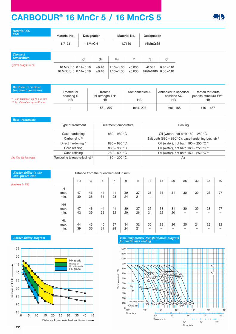
CARBODUR® 16 MnCr 5 / 16 MnCrS 5
C
0.14�0.190.14�0.19
Si
≤0.40≤0.40
Mn
1.10�1.301.10�1.30
P
≤0.035≤0.035
S
≤0.0350.020�0.040
Cr
0.80�1.100.80�1.10
16 MnCr 516 MnCrS 5
Material No.Code
Chemicalcomposition
Hmax.min.
HHmax.min.
HLmax.min.
* For diameters up to 150 mm** For diameters up to 60 mm
Treatment temperature
880 � 980 °C
880 � 980 °C
860 � 900 °C
780 � 820 °C
150 � 200 °C
Material No.
1.7131
Designation
16MnCr5
Material No.
1.7139
Designation
16MnCrS5
Treated forshearing S
HB
1)
Treated for strength TH*
HB
156 � 207
Soft-annealed A
HB
max. 207
Treated for ferrite-pearlite structure FP**
HB
140 � 187
Annealed to sphericalcarbides AC
HB
max. 165
2010
5040
85
B
FP
M
MS 9780
7765
AC1
AC3
10081
50
3 1520 60 65
3540
37
93
53
1200
1100
1000
900
800
700
600
500
400
300
200
100
0100 101 102 103 104 105
A
106
HV 10
100 101 102 103 104
100 101 102
10
5030
35
1530
60
394 317 278 251 243 221 207 199 187188
182 170 156
Tem
per
atur
in o
C
Zeit in s
Zeit in min
Zeit in h
Härtewerte
55
50
45
40
35
30
25
20
150 5 10 15 20 25 30 35 40 45
Abstand von der abgeschreckten Stirnfläche in mm
Här
te in
HR
C
HH-SorteÜberschneidungHH+HL-Sorte
HL-Sorte
Distance from the quenched end in mm
See flap for footnotes
22
Har
dne
ss in
HR
C
Distance from quenched end in mm
HH gradeOverlap ofHH + HL grade
HL grade
Tem
per
atur
e in
°C
Time in s
Time in min
Time in h
Hardness values

Cooling
Wasser (Öl),
Hot bath 160 � 250 °C, case-hardening box, air 4)
Water (oil), hot bath 160 � 250 °C 4)
Water (oil), hot bath 160 � 250 °C 4)
Water (oil), hot bath 160 � 250 °C 4)
Air
Type of treatment
Case-hardening
Carburising 2)
Direct hardening 3)
Core refining
Case refining
Tempering (stress-relieving) 5)
CARBODUR® 17 Cr 3
C
0.14�0.20
Si
≤0.40
Mn
0.60�0.90
P
≤0.035
S
≤0.035
Cr
0.70�1.00
Material No.Code
Chemicalcomposition
Typical analysis in %
1.5
4739
4742
4439
3
4435
4438
4135
5
4025
4030
3525
7
3320
3324
2920
9
29�
2920
25�
11
27�
27�
23�
13
25�
25�
21�
15
24�
24�
20�
20
23�
23�
��
25
21�
21�
��
Hmax.min.
HHmax.min.
HLmax.min.
Material No.
1.7016
Designation
17Cr3
Treatment temperature
880 � 980 °C
880 � 980 °C
860 � 900 °C
780 � 820 °C
150 � 200 °C
Treated forshearing S
HB
1)
Treatedfor strength TH
HB
Soft-annealed A
HB
max. 174
Treated for ferrite-pearlite structure FP
HB
Annealed to sphericalcarbides AC
HB
max. 155
Heat treatments
Hardness in varioustreatment conditions
Hardenability in theend-quench test
Hardness in HRC
Hardenability diagram Time-temperature-transformation diagramfor continuous cooling
3070 75
252515
1
3
67
20
F
M
MS 1565
15
AC1
AC3
35
5
20
1200
1100
1000
900
800
700
600
500
400
300
200
100
0100 101 102 103 104 105
A
106
HV 10
100 101 102 103 104
100 101 102
B85
1 5 3P
7572
446
439368 297 236 206
181160 151 141
Tem
per
atur
in o
C
Zeit in s
Zeit in min
Zeit in h
Härtewerte
55
50
45
40
35
30
25
20
150 5 10 15 20 25 30 35 40 45
Abstand von der abgeschreckten Stirnfläche in mm
Här
te in
HR
C
HH-SorteÜberschneidungHH+HL-Sorte
HL-Sorte
Distance from the quenched end in mm
See flap for footnotes
23
Har
dne
ss in
HR
C
Distance from quenched end in mm
HH gradeOverlap ofHH + HL grade
HL grade
Tem
per
atur
e in
°C
Time in s
Time in min
Time in h
Hardnessvalues

Cooling
Oil (water), hot bath 160 � 250 °C,
Salt bath (580 � 650 °C), case-hardening box, air 4)
Air, furnace
Oil (water), hot bath 160 � 250 °C 4)
Oil (water), hot bath 160 � 250 °C 4)
Air
Type of treatment
Case-hardening
Carburising 2)
Intermediate annealing
Core refining
Case refining
Tempering (stress-relieving) 5)
CARBODUR® 17 CrNi 6-6
C
0.14�0.20
Si
≤0.40
Mn
0.50�0.90
P
≤0.035
S
≤0.035
Cr
1.40�1.70
Ni
1.40�1.70
Material No.Code
1.5
4739
4742
4439
3
4738
4741
4438
5
4636
4639
4336
7
4535
4538
4235
9
4332
4336
3932
11
4230
4234
3830
13
4128
4132
3728
15
3926
3930
3526
20
3724
3728
3324
25
3522
3526
3122
30
3421
3425
3021
35
3420
3425
2920
40
3320
3324
2920
Hmax.min.
HHmax.min.
HLmax.min.
Treatment temperature
880 � 980 °C
630 � 650 °C
830 � 870 °C
780 � 820 °C
150 � 200 °C
Material No.
1.5918
Designation
17CrNi6-6
Treated forshearing S
HB
max. 255
Treated for strength TH*
HB
175 � 229
Soft-annealed A
HB
max. 229
Treated for ferrite-pearlite structure FP**
HB
156� 207
Annealed to sphericalcarbides AC
HB
max. 178
Typical analysis in %
Chemicalcomposition
Heat treatments
* For diameters up to 150 mm** For diameters up to 60 mm
Hardness in varioustreatment conditions
Hardenability in theend-quench test
Hardness in HRC
Hardenability diagram Time-temperature-transformation diagramfor continuous cooling
10
100 9790
35
6540
M
MS
AC1
AC3
1200
1100
1000
900
800
700
600
500
400
300
200
100
0100 101 102 103 104 105
A
106
HV 10
100 101 102 103 104
100 101 102
100
100
100
100 9585 70
3 515 30
55 60 70 75
10 3525
35 30
F
P
5
B100
60
409
394
357
318
297
276
270
266
262
242
222
203
175
161
157
154
154Härtewerte
Tem
per
atur
in o
C
Zeit in s
Zeit in min
Zeit in h
55
50
45
40
35
30
25
20
150 5 10 15 20 25 30 35 40 45
Abstand von der abgeschreckten Stirnfläche in mm
Här
te in
HR
C
HH-SorteÜberschneidungHH+HL-Sorte
HL-Sorte
Distance from the quenched end in mm
See flap for footnotes
24
Har
dne
ss in
HR
C
Distance from quenched end in mm
HH gradeOverlap ofHH + HL grade
HL grade
Tem
per
atur
e in
°C
Time in s
Time in min
Time in h
Hardness values
M
MS
AC1
AC3
1200
1100
1000
900
800
700
600
500
400
300
200
100
0100 101 102 103 104 105
A
106
HV 10
100 101 102 103 104
100 101 102
100 100 100 95 90 70
3030 5F P
65100
B
105
429 425 417 425 390 363 342 333 312 312 312 268 249Härtewerte
Tem
per
atur
in o
C
Zeit in s
Zeit in min
Zeit in h
Cooling
Oil (water), hot bath 160 � 250 °C,
Salt bath (580 � 650 °C), case-hardening box, air 4)
Air, furnace
Oil (water), hot bath 160 � 250 °C 4)
Oil (water), hot bath 160 � 250 °C 4)
Air
Type of treatment
Case-hardening
Carburising 2)
Direct hardening 3)
Core refining
Case refining
Tempering (stress-relieving) 5)
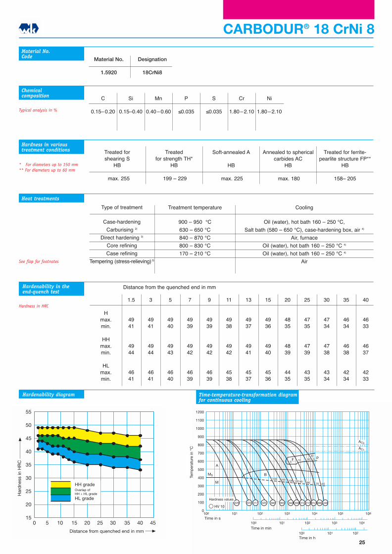
C
0.15�0.20
Si
0.15�0.40
Mn
0.40�0.60
P
≤0.035
S
≤0.035
Cr
1.80�2.10
Ni
1.80�2.10
Material No.Code
Chemicalcomposition
1.5
4941
4944
4641
3
4941
4944
4641
5
4940
4943
4640
7
4939
4942
4639
9
4939
4942
4639
11
4938
4942
4538
13
4937
4941
4537
15
4936
4940
4536
20
4835
4839
4435
25
4735
4739
4335
30
4734
4738
4334
35
4634
4638
4234
40
4633
4637
4233
Hmax.min.
HHmax.min.
HLmax.min.
Treatment temperature
900 � 950 °C
630 � 650 °C
840 � 870 °C
800 � 830 °C
170 � 210 °C
Material No.
1.5920
Designation
18CrNi8
CARBODUR® 18 CrNi 8
Treated forshearing S
HB
max. 255
Treated for strength TH*
HB
199 � 229
Soft-annealed A
HB
max. 225
Treated for ferrite-pearlite structure FP**
HB
158� 205
Annealed to sphericalcarbides AC
HB
max. 180
Typical analysis in %
Heat treatments
* For diameters up to 150 mm** For diameters up to 60 mm
Hardness in varioustreatment conditions
Hardenability in theend-quench test
Hardness in HRC
Hardenability diagram
55
50
45
40
35
30
25
20
150 5 10 15 20 25 30 35 40 45
Abstand von der abgeschreckten Stirnfläche in mm
Här
te in
HR
C
HH-SorteÜberschneidungHH+HL-Sorte
HL-Sorte
Distance from the quenched end in mm
Time-temperature-transformation diagramfor continuous cooling
See flap for footnotes
25
Har
dne
ss in
HR
C
Distance from quenched end in mm
HH gradeOverlap ofHH + HL grade
HL grade
Tem
per
atur
e in
°C
Time in s
Time in min
Time in h
Hardness values
30
97 95
90
M
MS
AC1
AC3
1200
1100
1000
900
800
700
600
500
400
300
200
100
0100 101 102 103 104 105
A
106
HV 10
100 101 102 103 104
100 101 102
60 80
80 55 15
F
5
B
3
100 100 100 100 100
5 2045 55 65
30 P
426425
418383
360343
336327
314 286261
242215 175
Härtewerte
Tem
per
atur
in o
C
Zeit in s
Zeit in min
Zeit in h
Cooling
Oil (water), hot bath 160 � 250 °C,
Salt bath (580 � 650 °C), case-hardening box, air 4)
Air, furnace
Oil (water), hot bath 160 � 250 °C 4)
Oil (water), hot bath 160 � 250 °C 4)
Air
1.5
4840
4843
4540
3
4840
4843
4540
5
4839
4842
4539
7
4838
4841
4538
9
4737
4740
4437
11
4736
4740
4336
13
4635
4639
4235
15
4634
4638
4234
20
4432
4436
4032
25
4331
4335
3931
30
4230
4234
3830
35
4129
4133
3729
40
4129
4133
3729
Type of treatment
Case-hardening
Carburising 2)
Intermediate annealing
Core refining
Case refining
Tempering (stress-relieving) 5)
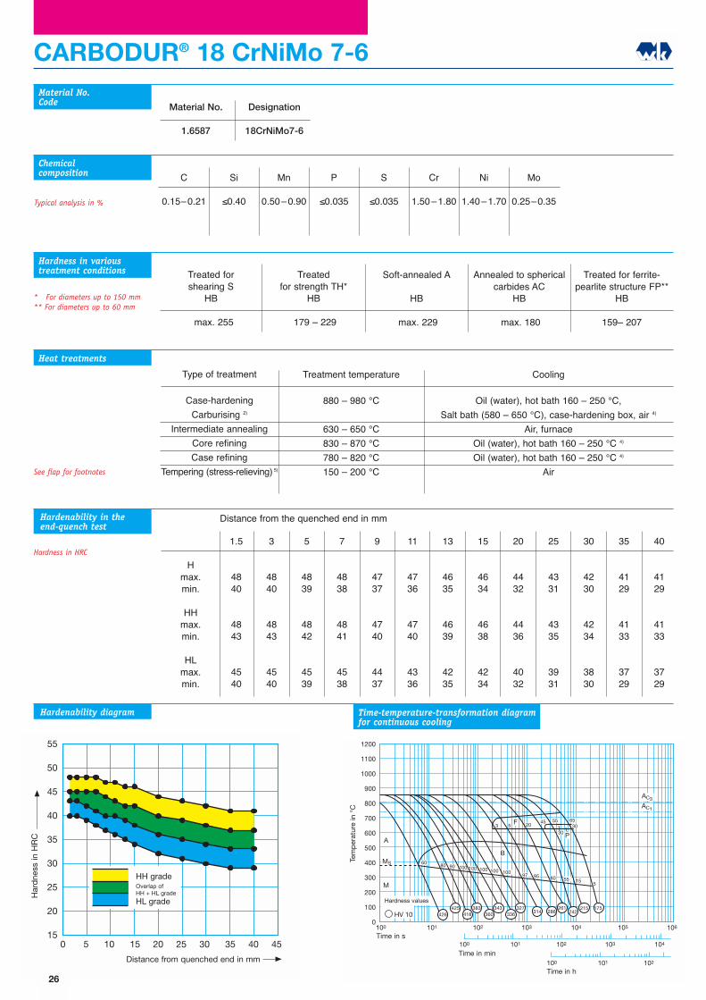
CARBODUR® 18 CrNiMo 7-6
C
0.15�0.21
Si
≤0.40
Mn
0.50�0.90
P
≤0.035
S
≤0.035
Cr
1.50�1.80
Ni
1.40�1.70
Mo
0.25�0.35
Material No.Code
Chemicalcomposition
Hmax.min.
HHmax.min.
HLmax.min.
Treatment temperature
880 � 980 °C
630 � 650 °C
830 � 870 °C
780 � 820 °C
150 � 200 °C
Material No.
1.6587
Designation
18CrNiMo7-6
Treated forshearing S
HB
max. 255
Treated for strength TH*
HB
179 � 229
Soft-annealed A
HB
max. 229
Treated for ferrite-pearlite structure FP**
HB
159� 207
Annealed to sphericalcarbides AC
HB
max. 180
Typical analysis in %
Heat treatments
* For diameters up to 150 mm** For diameters up to 60 mm
Hardness in varioustreatment conditions
Hardenability in theend-quench test
Hardness in HRC
Hardenability diagram Time-temperature-transformation diagramfor continuous cooling
55
50
45
40
35
30
25
20
150 5 10 15 20 25 30 35 40 45
Abstand von der abgeschreckten Stirnfläche in mm
Här
te in
HR
C
HH-SorteÜberschneidungHH+HL-Sorte
HL-Sorte
Distance from the quenched end in mm
See flap for footnotes
26
Har
dne
ss in
HR
C
Distance from quenched end in mm
HH gradeOverlap ofHH + HL grade
HL grade
Tem
per
atur
e in
°C
Time in s
Time in min
Time in h
Hardness values
Cooling
Oil (water), hot bath 160 � 250 °C,
Salt bath (580 � 650 °C), case-hardening box, air 4)
Oil, hot bath 160 � 250 °C 4)
Oil, hot bath 160 � 250 °C 4)
Oil, hot bath 160 � 250 °C 4)
Air
1.5
4939
4942
4639
3
4939
4942
4639
5
4838
4841
4538
7
4737
4740
4437
9
4636
4639
4336
11
4535
4538
4235
13
4433
4437
4033
15
4432
4436
4032
20
4230
4234
3830
25
4128
4132
3728
30
3926
3930
3526
35
3825
3829
3425
40
3823
3828
3323
Type of treatment
Case-hardening
Carburising 2)
Direct hardening 3)
Core refining
Case refining
Tempering (stress-relieving) 5)
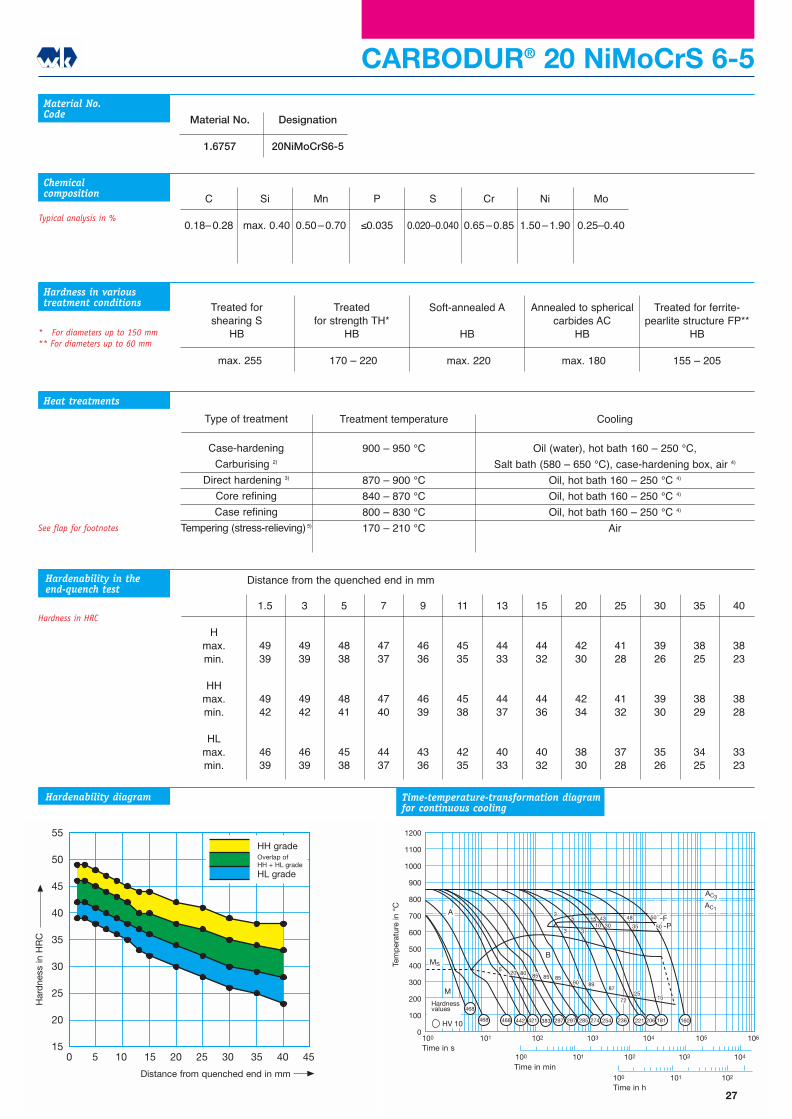
C
0.18�0.28
Si
max. 0.40
Mn
0.50�0.70
P
≤0.035
S
0.020�0.040
Cr
0.65�0.85
Ni
1.50�1.90
Mo
0.25�0.40
Material No.Code
Typical analysis in %
Hmax.min.
HHmax.min.
HLmax.min.
Treatment temperature
900 � 950 °C
870 � 900 °C
840 � 870 °C
800 � 830 °C
170 � 210 °C
Material No.
1.6757
Designation
20NiMoCrS6-5
CARBODUR® 20 NiMoCrS 6-5
Treated forshearing S
HB
max. 255
Treated for strength TH*
HB
170 � 220
Soft-annealed A
HB
max. 220
Treated for ferrite-pearlite structure FP**
HB
155 � 205
Annealed to sphericalcarbides AC
HB
max. 180
Chemicalcomposition
Heat treatments
* For diameters up to 150 mm** For diameters up to 60 mm
Hardness in varioustreatment conditions
Hardenability in theend-quench test
Hardness in HRC
Hardenability diagram Time-temperature-transformation diagramfor continuous cooling
310
M
MS
90
AC1
AC3
530
1200
1100
1000
900
800
700
600
500
400
300
200
100
0100 101 102 103 104 105
A
106
HV 10
100 101 102 103 104
100 101 102
89
153
87
7225
15
35
48 50
-P-F
B
85858580205
3
43
50
468
468 468 442 421 383 297 297 285 274 254 236 221 206 181 160
Härtewerte
Tem
per
atur
in o
C
Zeit in s
Zeit in min
Zeit in h
55
50
45
40
35
30
25
20
150 5 10 15 20 25 30 35 40 45
Abstand von der abgeschreckten Stirnfläche in mm
Här
te in
HR
C
HH-SorteÜberschneidungHH+HL-Sorte
HL-Sorte
Distance from the quenched end in mm
See flap for footnotes
27
Har
dne
ss in
HR
C
Distance from quenched end in mm
HH gradeOverlap ofHH + HL grade
HL grade
Tem
per
atur
e in
°C
Time in s
Time in min
Time in h
Hardnessvalues

Cooling
Oil (water), hot bath 160 � 250 °C, 4)
Salt bath (580 � 680 °C), case-hardening box, air 4)
Oil (water), hot bath 160 � 250 °C 4)
Oil (water), hot bath 160 � 250 °C 4)
Oil (water), hot bath 160 � 250 °C 4)
Air
1.5
4941
4944
4641
3
4939
4942
4639
5
4836
4840
4436
7
4633
4637
4233
9
4330
4334
3930
11
4228
4233
3728
13
4126
4131
3626
15
3925
3930
3425
20
3723
3728
3223
25
3521
3526
3021
30
34�
3425
29�
35
33�
3324
28�
40
32�
3223
27�
Type of treatment
Case-hardening
Carburising 2)
Direct hardening 3)
Core refining
Case refining
Tempering (stress-relieving) 5)
C
0.17�0.220.17�0.22
Si
≤0.40≤0.40
Mn
1.10�1.401.10�1.40
P
≤0.035≤0.035
S
≤0.0350.020�0.040
Cr
1.00�1.301.00�1.30
20 MnCr 520 MnCrS 5
Material No.Code
Hmax.min.
HHmax.min.
HLmax.min.
* For diameters up to 150 mm** For diameters up to 60 mm
Treatment temperature
880 � 980 °C
880 � 980 °C
860 � 900 °C
780 � 820 °C
150 � 200 °C
Material No.
1.7147
Designation
20MnCr5
Material No.
1.7149
Designation
20MnCrS5
CARBODUR® 20 MnCr 5 / 20 MnCrS 5
Treated forshearing S
HB
1)
Treated for strength TH*
HB
170 � 217
Soft-annealed A
HB
max. 217
Treated for ferrite-pearlite structure FP**
HB
152 � 201
Annealed to sphericalcarbides AC
HB
max. 180
Chemicalcomposition
Typical analysis in %
Heat treatments
Hardness in varioustreatment conditions
Hardenability in theend-quench test
Hardness in HRC
Hardenability diagram Time-temperature-transformation diagramfor continuous cooling
4040 40
10
60
60
B
F
M
MS 5065
55
45
AC1
AC3
8780
6065
35
1200
1100
1000
900
800
700
600
500
400
300
200
100
0100 101 102 103 104 105
A
106
100 101 102 103 104
100 101 102
15
25
40
5040
35
6060
25 P
60
405 342 302 274 263 238 212 187 171 160 182 162 153
HV 10
Tem
per
atur
in o
C
Zeit in s
Zeit in min
Zeit in h
Härtewerte
55
50
45
40
35
30
25
20
150 5 10 15 20 25 30 35 40 45
Abstand von der abgeschreckten Stirnfläche in mm
Här
te in
HR
C
HH-SorteÜberschneidungHH+HL-Sorte
HL-Sorte
Distance from the quenched end in mm
See flap for footnotes
28
Har
dne
ss in
HR
C
Distance from quenched end in mm
HH gradeOverlap ofHH + HL grade
HL grade
Tem
per
atur
e in
°C
Time in s
Time in min
Time in h
Hardness values
30 30
90
B
M
MS95
9585 70
AC1
AC3
9595
5
60 65
3015
1200
1100
1000
900
800
700
600
500
400
300
200
100
0100 101 102 103 104 105
A
106
HV 10
100 101 102 103 104
100 101 102
15
6555
3025
10 5 5 5
3 5 1065
30
70
30
70
30P
F
370 283 260 240 238 228 210 189 176 165 181156
152149
Härtewerte
Tem
per
atur
in o
C
Zeit in s
Zeit in min
Zeit in h
Cooling
Oil (water), hot bath 160 � 250 °C,4)
Oil, hot bath 160 � 250 °C 4)
Oil, hot bath 160 � 250 °C 4)
Oil, hot bath 160 � 250 °C 4)
Air
1.5
4941
4944
4641
3
4737
4740
4437
5
4431
4435
4031
7
4127
4132
3627
9
3824
3829
3324
11
3522
3526
3122
13
33�
3324
29�
15
31�
3122
27�
20
28�
28�
24�
25
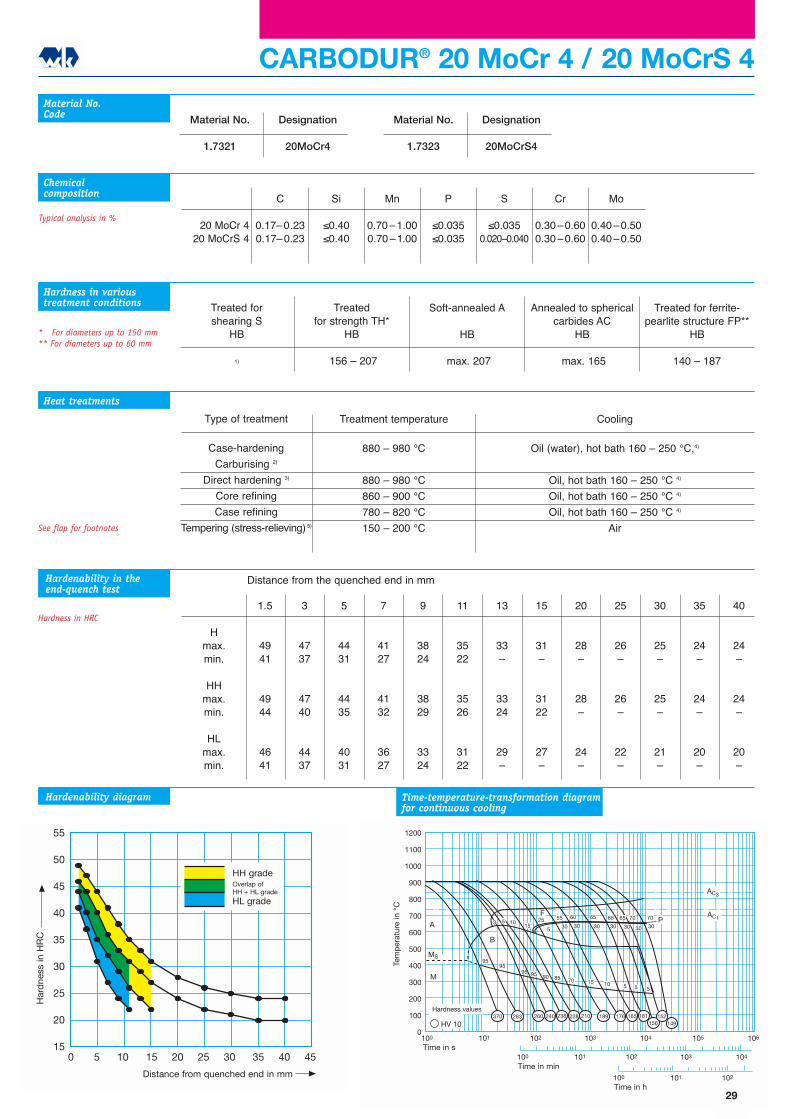
26�
26�
22�
30
25�
25�
21�
35
24�
24�
20�
40
24�
24�
20�
Type of treatment
Case-hardening
Carburising 2)
Direct hardening 3)
Core refining
Case refining
Tempering (stress-relieving) 5)
CARBODUR® 20 MoCr 4 / 20 MoCrS 4
C
0.17�0.230.17�0.23
Si
≤0.40≤0.40
Mn
0.70�1.000.70�1.00
P
≤0.035≤0.035
S
≤0.0350.020�0.040
Cr
0.30�0.600.30�0.60
Mo
0.40�0.500.40�0.50
20 MoCr 420 MoCrS 4
Material No.Code
Chemicalcomposition
Hmax.min.
HHmax.min.
HLmax.min.
Treatment temperature
880 � 980 °C
880 � 980 °C
860 � 900 °C
780 � 820 °C
150 � 200 °C
Material No.
1.7321
Designation
20MoCr4
Material No.
1.7323
Designation
20MoCrS4
Treated forshearing S
HB
1)
Treated for strength TH*
HB
156 � 207
Soft-annealed A
HB
max. 207
Treated for ferrite-pearlite structure FP**
HB
140 � 187
Annealed to sphericalcarbides AC
HB
max. 165
Typical analysis in %
Heat treatments
* For diameters up to 150 mm** For diameters up to 60 mm
Hardness in varioustreatment conditions
Hardenability in theend-quench test
Hardness in HRC
Hardenability diagram Time-temperature-transformation diagramfor continuous cooling
55
50
45
40
35
30
25
20
150 5 10 15 20 25 30 35 40 45
Abstand von der abgeschreckten Stirnfläche in mm
Här
te in
HR
C
HH-SorteÜberschneidungHH+HL-Sorte
HL-Sorte
Distance from the quenched end in mm
See flap for footnotes
29
Har
dne
ss in
HR
C
Distance from quenched end in mm
HH gradeOverlap ofHH + HL grade
HL grade
Tem
per
atur
e in
°C
Time in s
Time in min
Time in h
Hardness values
1
5 5
40 55 60
84
B
M
MS
65
AC1
AC3
85
91
1200
1100
1000
900
800
700
600
500
400
300
200
100
0100 101 102 103 104 105
A
106
HV 10
100 101 102 103 104
100 101 102
75
40
F
97
96
7949
5
P2525
75
40101
1510
5
453453
453 426 313 283 276 245 239
234
210 182 159 148 140
Härtewerte
Tem
per
atur
in o
C
Zeit in s
Zeit in min
Zeit in h
Cooling
Oil (water), hot bath 160 � 250 °C,
Salt bath (580 � 650 °C), case-hardening box, air 4)
Oil, hot bath 160 � 250 °C 4)
Oil, hot bath 160 � 250 °C 4)
Oil, hot bath 160 � 250 °C 4)
Air
Type of treatment
Case-hardening
Carburising 2)
Direct hardening 3)
Core refining
Case refining
Tempering (stress-relieving) 5)
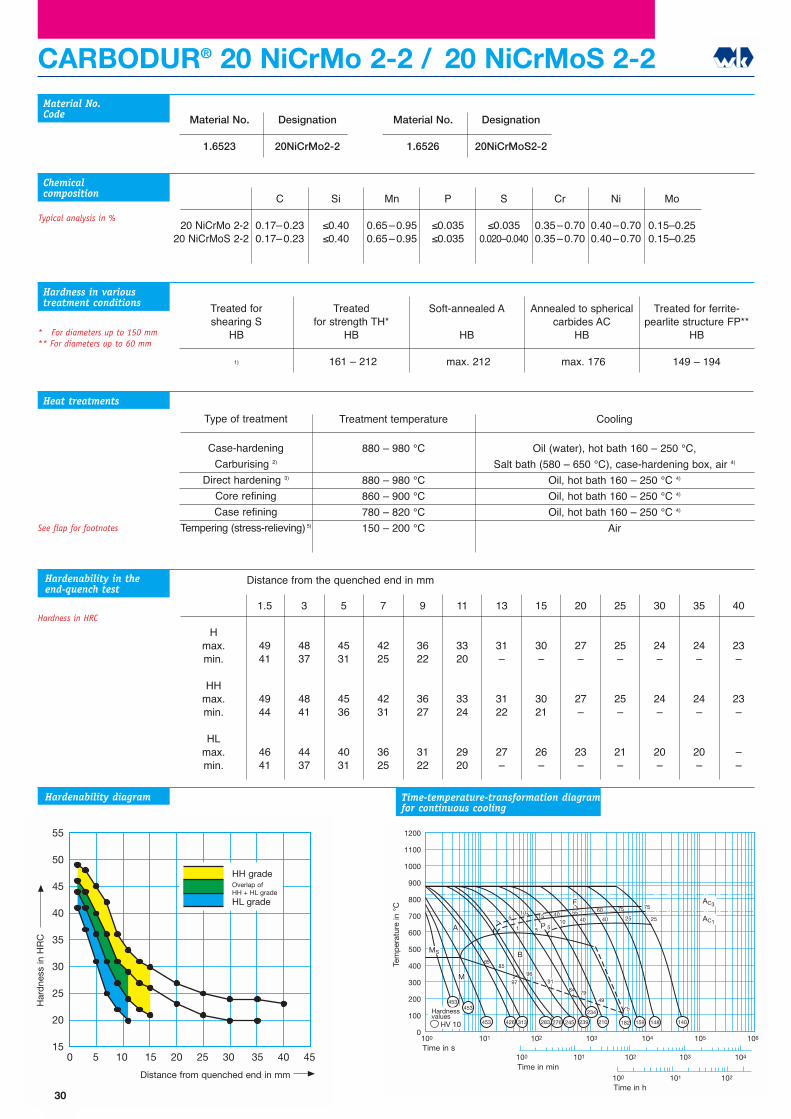
CARBODUR® 20 NiCrMo 2-2 / 20 NiCrMoS 2-2
C
0.17�0.230.17�0.23
Si
≤0.40≤0.40
Mn
0.65�0.950.65�0.95
P
≤0.035≤0.035
S
≤0.0350.020�0.040
Cr
0.35�0.700.35�0.70
Ni
0.40�0.700.40�0.70
Mo
0.15�0.250.15�0.25
20 NiCrMo 2-220 NiCrMoS 2-2
Material No.Code
Chemicalcomposition
1.5
4941
4944
4641
3
4837
4841
4437
5
4531
4536
4031
7
4225
4231
3625
9
3622
3627
3122
11
3320
3324
2920
13
31�
3122
27�
15
30�
3021
26�
20
27�
27�
23�
25
25�
25�
21�
30
24�
24�
20�
35
24�
24�
20�
40
23�
23�
��
Hmax.min.
HHmax.min.
HLmax.min.
Treatment temperature
880 � 980 °C
880 � 980 °C
860 � 900 °C
780 � 820 °C
150 � 200 °C
Material No.
1.6523
Designation
20NiCrMo2-2
Material No.
1.6526
Designation
20NiCrMoS2-2
Treated forshearing S
HB
1)
Treated for strength TH*
HB
161 � 212
Soft-annealed A
HB
max. 212
Treated for ferrite-pearlite structure FP**
HB
149 � 194
Annealed to sphericalcarbides AC
HB
max. 176
Typical analysis in %
Heat treatments
* For diameters up to 150 mm** For diameters up to 60 mm
Hardness in varioustreatment conditions
Hardenability in theend-quench test
Hardness in HRC
Hardenability diagram Time-temperature-transformation diagramfor continuous cooling
55
50
45
40
35
30
25
20
150 5 10 15 20 25 30 35 40 45
Abstand von der abgeschreckten Stirnfläche in mm
Här
te in
HR
C
HH-SorteÜberschneidungHH+HL-Sorte
HL-Sorte
Distance from the quenched end in mm
See flap for footnotes
30
Har
dne
ss in
HR
C
Distance from quenched end in mm
HH gradeOverlap ofHH + HL grade
HL grade
Tem
per
atur
e in
°C
Time in s
Time in min
Time in h
Hardnessvalues
Cooling
Oil (water), hot bath 160 � 250 °C,
Salt bath (580 � 650 °C), case-hardening box, air 4)
Oil, hot bath 160 � 250 °C 4)
Oil, hot bath 160 � 250 °C 4)
Oil, hot bath 160 � 250 °C 4)
Air
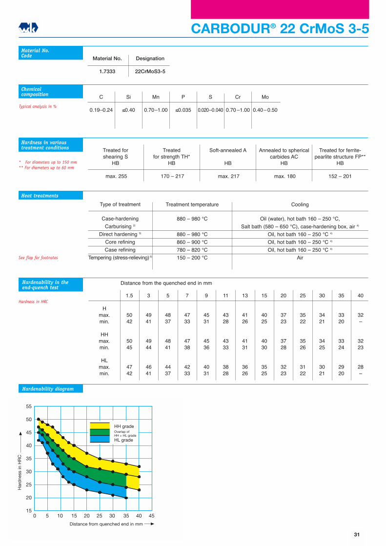
Type of treatment
Case-hardening
Carburising 2)
Direct hardening 3)
Core refining
Case refining
Tempering (stress-relieving) 5)
C
0.19�0.24
Si
≤0.40
Mn
0.70�1.00
P
≤0.035
S
0.020�0.040
Cr
0.70 �1.00
Mo
0.40�0.50
Material No.Code
Chemicalcomposition
Treatment temperature
880 � 980 °C
880 � 980 °C
860 � 900 °C
780 � 820 °C
150 � 200 °C
Material No.
1.7333
Designation
22CrMoS3-5
CARBODUR® 22 CrMoS 3-5
Treated forshearing S
HB
max. 255
Treated for strength TH*
HB
170 � 217
Soft-annealed A
HB
max. 217
Treated for ferrite-pearlite structure FP**
HB
152 � 201
Annealed to sphericalcarbides AC
HB
max. 180
Typical analysis in %
Heat treatments
* For diameters up to 150 mm** For diameters up to 60 mm
Hardness in varioustreatment conditions
Hardenability in theend-quench test
Hardness in HRC
Hardenability diagram
1.5
5042
5045
4742
3
4941
4944
4641
5
4837
4841
4437
7
4733
4738
4233
9
4531
4536
4031
11
4328
4333
3828
13
4126
4131
3626
15
4025
4030
3525
20
3723
3728
3223
25
3522
3526
3122
30
3421
3425
3021
35
3320
3324
2920
40
32�
3223
28�
Hmax.min.
HHmax.min.
HLmax.min.
55
50
45
40
35
30
25
20
150 5 10 15 20 25 30 35 40 45
Abstand von der abgeschreckten Stirnfläche in mm
Här
te in
HR
C
HH-SorteÜberschneidungHH+HL-Sorte
HL-Sorte
Distance from the quenched end in mm
See flap for footnotes
31
Har
dne
ss in
HR
C
Distance from quenched end in mm
HH gradeOverlap ofHH + HL grade
HL grade
32
Hardenability
Effect of alloying elements
on hardenability
Based on the composition of the
alloys, case-hardening steels can
be classified as:
• unalloyed
• chrome-alloyed
• manganese-chrome and molyb-
denum-chrome-alloyed
• nickel-chrome-alloyed
• nickel-chrome-molybdenum-
alloyed and
• chrome-nickel-molybdenum-
alloyed case-hardening steels.
The alloying elements affect the
hardenability of the base material
and the hardenability of the car-
burised surface layer.
The hardenability of the base
material is identified by means of
the end-quench test according to
DIN 50 191 and is an important
parameter for determining
hardness in the core, since case-
hardened components are only
tempered at low temperatures, up
to approximately 180 °C, in order
to ensure high surface hardness.
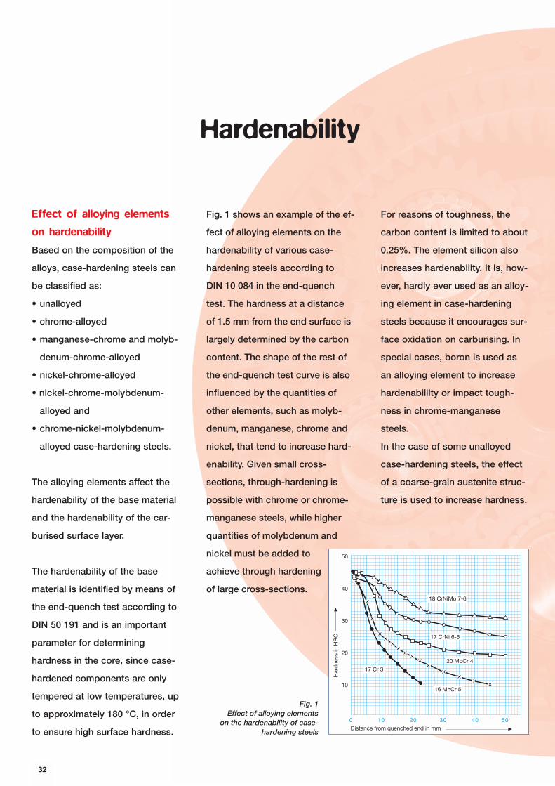
Fig. 1 shows an example of the ef-
fect of alloying elements on the
hardenability of various case-
hardening steels according to
DIN 10 084 in the end-quench
test. The hardness at a distance
of 1.5 mm from the end surface is
largely determined by the carbon
content. The shape of the rest of
the end-quench test curve is also
influenced by the quantities of
other elements, such as molyb-
denum, manganese, chrome and
nickel, that tend to increase hard-
enability. Given small cross-
sections, through-hardening is
possible with chrome or chrome-
manganese steels, while higher
quantities of molybdenum and
nickel must be added to
achieve through hardening
of large cross-sections.
For reasons of toughness, the
carbon content is limited to about
0.25%. The element silicon also
increases hardenability. It is, how-
ever, hardly ever used as an alloy-
ing element in case-hardening
steels because it encourages sur-
face oxidation on carburising. In
special cases, boron is used as
an alloying element to increase
hardenabililty or impact tough-
ness in chrome-manganese
steels.
In the case of some unalloyed
case-hardening steels, the effect
of a coarse-grain austenite struc-
ture is used to increase hardness.
Har
dne
ss in
HR
C
Distance from quenched end in mm
case-hardening steels50
40
30
20
10
0 10 20 30 40 50
18 CrNiMo 7-6
17 CrNi 6-6
20 MoCr 4
16 MnCr 5
17 Cr 3
Fig. 1Effect of alloying elements
on the hardenability of case-hardening steels

33
Technical information
Quite apart from their influence
on hardness in the core, the
hardness and the hardness profile
in the carburised surface layer
have an important effect on the
properties of case-hardened
components. A surface hardness
of 57 - 63 HRC has proved to the
best for optimum wear resistance.
This degree of hardness is
achieved largely independently of
the steel composition, with a car-
bon content at the surface of
some 0.7%. Higher carbon con-
tents in the surface layer provide
only a slight increase in hardness.
Supercarburisation in the surface
layer may result in reduced
toughness due to precipitation of
secondary cementite and a
hardness loss caused by increas-
ing proportions of residual aus-
tenite.
The case depth, defined as the
distance from the surface of a
case-hardened workpiece to the
point whose Vickers hardness is
usually 550 HV1 (see DIN 50 190),
is determined by the depth of
carburisation, the heating and
cooling conditions during hard-
ening and the hardenability in the
carburised surface layer.
Correlations valid for the base
material cannot be applied to the
hardenability of the surface layer,
since the effect of alloying ele-
ments on hardenability also
depends on the carbon content.
Up to a carbon content of about
0.5%, the improvement in harden-
ability brought about by molyb-
denum, chrome and manganese
increases, only to drop again at
higher carbon contents.
Fig. 2 shows the case depth of
various case-hardening steels
with the same carbon distribution
in the surface layer. According to
this, case depth of the 17 Cr 3
steel (0.80 mm) is doubled in the
17 CrNi 6-6 steel (1.56 mm) due to
the different alloy contents under
otherwise identical conditions.
Distance from the surface in mm
Car
bon
con
tent
in %
by
wei
ght
%
0.90
0.80
0.70
0.60
0.50
0.40
0.30
0.20
0.10
00 0.4 0.8 1.2 1.6 2.0 2.4 2.8
17 Cr 320 NiCrMo 2-220 MoCr 416 MnCr 520 NiMoCr 6-517 CrNi 6-6
C
0.46 1.50 mm
0.39
0.340.37
0.330.35 % C
Eht
0.80
1.16
1.35
1.52
1.56
1.42
0.60
(acc. to U. Wyss)
Fig. 2: Case depth of various case-harden-ing steels with the same carbon profile(acc. to U. Wyss)
Suitability for direct
hardening
An important criterion in the
choice of a case-hardening steel
is its suitability for direct harden-
ing. The most common methods
of case hardening are direct hard-
ening (Fig. 10, Hardening from the
carburisation heat) and single
hardening after cooling from the
case (Fig. 11). Mainly for reasons
of cost effectiveness, direct hard-
ening is increasingly being given
preference in mass production
methods (see chapter on Heat
Treatment).
The prerequisites for the suitability
of a case-hardening steel for
direct hardening are satisfactory
fine-grain stability at the carburis-
ing temperature and low residual
austenite after hardening. The
residual austenite content after
hardening increases with increas-
ing chrome content and carburis-
ing temperature. Fig. 3 illustrates
this relationship, using the
20 MoCr 4, 20 NiMoCr 6 5,
16 MnCr 5, 20 MnCr 5,
17 CrNi 6-6 and 18 CrNi 8
steels as examples.
Although differences in the
proportions of residual aus-
tenite in the various steels
remain relatively small at carbu-
rising temperatures around 900 °C
with subsequent direct hardening,
they increase rapidly and pro-
gressively at higher carburising
temperatures. For economic rea-
sons, however, ever higher car-
burising temperatures are being
aimed at for direct hardening.
Given the same carburising time
and the same carbon potential in
the carburising medium, the pro-
portion of residual austenite in
the 17 CrNi 6-6 and 18 CrNi 8
steels with 1.6 to 1.8% chrome is
appreciably higher than, for exam-
ple, in the 20 MoCr 4 steel with
approximately 0.4% chrome. The
hardness decreases at carbon
contents > 0.7% at the surface,
which increases the proportions
of residual austenite (Fig. 4).
The suitability of a steel for direct
hardening can also be identified
by the range of carbon contents
at the surface with which a cer-
tain minimum hardness can be
achieved. According to this, the
20 MoCr 4 steel is more suitable
for direct hardening than, for
example, the 18 CrNi 8 steel.
Advances in the development of
modern gas carburising plants,
Chrome content in % by weight
Res
idua
l aus
teni
te c
onte
nt in
%
Carborisingtemperaturein °C:
Carborising time: 3 h100
90
80
70
60
50
40
30
20
10
00.4 0.6 0.8 1.0 1.2 1.4 1.6 1.8
1000
950
900
chrome content of the steels tested
16 M
nCr
5
20 M
nCr
5
18 C
rNi 8
17 C
rNi 6
-620 N
iMoC
r 6-
5
20 M
oCr
4
Har
dne
ss in
HV
0.5
Carbon Content in % by weight
Direct hardening925 °C/oil
direct hardening
900
800
700
600
500
400
300
0 0.1 0.2 0.3 0.4 0.5 0.6 0.7 0.8 0.9 1.0 1.1 1.2 1.3
20 MoCr 420 NiMoCr 6-518 CrNi 816 MnCr 5
Fig. 3: Residual austenite content as afunction of chrome content and carburis-ing temperature
Fig. 4: Hardness as a function ofthe carbon content of the surface
layer after direct hardening
34
with their precise, specific control
of the carbon potential and the
carburising cycle, mean that
practically all case-hardening
steels can be direct-hardened,
regardless of their alloy content.
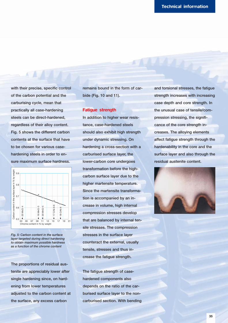
Fig. 5 shows the different carbon
contents at the surface that have
to be chosen for various case-
hardening steels in order to en-
sure maximum surface hardness.
The proportions of residual aus-
tenite are appreciably lower after
single hardening since, on hard-
ening from lower temperatures
adjusted to the carbon content at
the surface, any excess carbon
Fig. 5: Carbon content in the surfacelayer targeted during direct hardeningto obtain maximum possible hardnessas a function of the chrome content
remains bound in the form of car-
bide (Fig. 10 and 11).
Fatigue strength
In addition to higher wear resis-
tance, case-hardened steels
should also exhibit high strength
under dynamic stressing. On
hardening a cross-section with a
carburised surface layer, the
lower-carbon core undergoes
transformation before the high-
carbon surface layer due to the
higher martensite temperature.
Since the martensite transforma-
tion is accompanied by an in-
crease in volume, high internal
compression stresses develop
that are balanced by internal ten-
sile stresses. The compression
stresses in the surface layer
counteract the external, usually
tensile, stresses and thus in-
crease the fatigue strength.
The fatigue strength of case-
hardened components also
depends on the ratio of the car-
burised surface layer to the non-
carburised section. With bending
and torsional stresses, the fatigue
strength increases with increasing
case depth and core strength. In
the unusual case of tensile/com-
pression stressing, the signifi-
cance of the core strength in-
creases. The alloying elements
affect fatigue strength through the
hardenability in the core and the
surface layer and also through the
residual austenite content.
Chrome content in % by weight
Car
bon
con
tent
in t
he s
urfa
ce la
yer
in %
by
wei
ght
0.9
0.8
0.7
0.6
0.50.3 0.5 0.7 0.9 1.1 1.3 1.5 1.7 1.9 2.1
20 M
oCr
4
16 M
nCr
5
20 M
nCr
5
17 C
rNi 6
-6
18 C
rNi 8
35
Technical information
Austenite grain size
Fine-grain stability in case-
hardening steels is particularly
important at the high tempera-
tures reached during direct hard-
ening, due to the fact that grain
growth with coarse or mixed grain
can lead to the danger of distor-
tion and reduced toughness. By
selectively balancing the quanti-
ties of aluminium and nitrogen,
the inhibiting effect of aluminium
nitride precipitations on grain
growth can be used to achieve a
largely stable fine-grain structure.
According to DIN 17 210, fine
grain structure is assured after
treatment at 930 +/- 10 °C/4 h/
water. Prior hot forming and heat
treatments can have a significant
effect on the stability of the fine
grain. In disputed cases, anneal-
ing treatment at 1150 °C/30 min/
air is recommended as pre-
treatment, in order to produce a
uniform initial state.
Toughness of the surface
layer under impact loading
Case-hardened components must
remain ductile under high dynam-
ic stressing in order to avoid
brittle factures. Since the high-
carbon martensite in the surface
layer exhibits only low toughness,
the toughness of the component
is determined largely by the
depth of the carburised surface
layer and the toughness of the
core material. The impact tough-
ness of the component dimin-
ishes with increasing case depth.
For reasons connected with the
fatigue strength, however, the
case depth should not be too
small. The toughnesss of the sur-
face layer can be improved by
choosing a nickel content > 1.5%.
To date, no standard test for the
characterisation of the impact
toughness of case-hardened
steels has been accepted. One
frequently used method is the
Brugger test, with which the
maximum impact strength of a
case-hardened notched impact
specimen is measured.
36
37
Machining and heat treatment
Technical information
Chipless forming
Case-hardening steels are well
suited to hot forming. Due to the
low carbon content, they possess
good cold-working properties
that, however, deteriorate with
increasing carbon and alloy con-
tents. Depending on the chemical
composition, the choice of a suit-
able structure (AC, FP) can im-
prove cold-forming properties.
Chip machining
Chip machining of case-harden-
ing steels is affected by the struc-
tural state, the strength and non-
metallic inclusions (sulphides,
oxides).
Ferritic-pearlitic structures, such
as can be achieved with un-
alloyed or low-alloy case-harden-
ing steels like Ck 15 and 17 Cr 3
by controlled cooling from the
forming temperature, are espe-
cially well suited for chip machin-
ing. Special heat treatment (FP
annealing) is required for higher-
alloyed steels. At very low hard-
ness values, case-hardening
steels tend to “smear” and form
built-up edges. In such cases,
heat treatment to a particular
strength (“TH”) is of advantage.
With high-alloy nickel-chrome or
nickel-chrome-molybdenum case-
hardening steels, the transition to
the ferrite-pearlite stage is often
incomplete, leaving traces of
bainite and a banded structure
that reduce machinability. These
steels are therefore also ma-
chined in the AC-annealed condi-
tion.
Case-hardening steels are fre-
quently produced with a con-
trolled sulphur content of 0.020 -
0.035%. Machinability is then
improved by an increase in sul-
phide inclusions. Deliberate con-
trol of the oxide inclusions
(calcium treatment) also
allows the machinability of
case-hardening steels to
be changed for the better.
Heat treatments for as-
supplied conditions
Depending on the product con-
cerned and the anticipated pro-
cessing, case-hardening steels
can be supplied in various treated
conditions. The most important
heat treatments are described
below. Table 1 provides an over-
view of the Brinell hardness
values that should be chosen for
these conditions.
Treatment for shearing S
(Fig. 6, Curve 1)
Appropriate cooling and/or
annealing to achieve a maximum
hardness of 255 HB.
Time
Tem
per
atur
e Soft annealing, A
annealing to spherical, AC
Treating forshearing, S
2
3
4
1
AC3
AC1
Fig. 6: Schematic representation of the temperature/time profile when
treating for shearing (S), soft-annealing (A) andannealing to spherical carbides (AC)
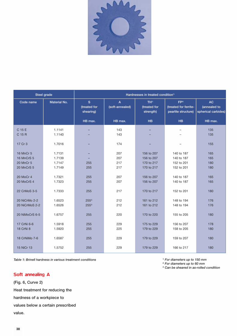
Code name Material No. S
(treated for
shearing)
HB max.
A
(soft-annealed)
HB max.
TH1)
(treated for
strength)
HB
FP2)
(treated for ferrite-
pearlite structure)
HB
AC
(annealed to
spherical carbides)
HB max.
Soft annealing A
(Fig. 6, Curve 2)
Heat treatment for reducing the
hardness of a workpiece to
values below a certain prescribed
value.
38
Table 1: Brinell hardness in various treatment conditions 1) For diameters up to 150 mm2) For diameters up to 60 mm3) Can be sheared in as-rolled condition
Hardnesses in treated condition1)Steel grade
C 15 E 1.1141 – 143 – – 135
C 15 R 1.1140 – 143 – – 135
17 Cr 3 1.7016 – 174 – – 155
16 MnCr 5 1.7131 – 207 156 to 207 140 to 187 165
16 MnCrS 5 1.7139 – 207 156 to 207 140 to 187 165
20 MnCr 5 1.7147 255 217 170 to 217 152 to 201 180
20 MnCrS 5 1.7149 255 217 170 to 217 152 to 201 180
20 MoCr 4 1.7321 255 207 156 to 207 140 to 187 165
20 MoCrS 4 1.7323 255 207 156 to 207 140 to 187 165
22 CrMoS 3-5 1.7333 255 217 170 to 217 152 to 201 180
20 NiCrMo 2-2 1.6523 2553) 212 161 to 212 148 to 194 176
20 NiCrMoS 2-2 1.6526 2553) 212 161 to 212 148 to 194 176
20 NiMoCrS 6-5 1.6757 255 220 170 to 220 155 to 205 180
17 CrNi 6-6 1.5918 255 229 175 to 229 156 to 207 178
18 CrNi 8 1.5920 255 225 179 to 229 158 to 205 180
18 CrNiMo 7-6 1.6587 255 229 179 to 229 159 to 207 180
15 NiCr 13 1.5752 255 229 179 to 229 166 to 217 180
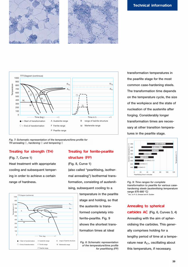
Treating for strength (TH)
(Fig. 7, Curve 1)
Heat treatment with appropriate
cooling and subsequent temper-
ing in order to achieve a certain
range of hardness.
Treating for ferrite-pearlite
structure (FP)
(Fig. 8, Curve 1)
(also called “pearlitising, isother-
mal annealing”) Isothermal trans-
formation, consisting of austenit-
ising, subsequent cooling to a
temperature in the pearlite
stage and holding, so that
the austenite is trans-
formed completely into
ferrite-pearlite. Fig. 9
shows the shortest trans-
formation times at ideal
transformation temperatures in
the pearlite stage for the most
common case-hardening steels.
The transformation time depends
on the temperature cycle, the size
of the workpiece and the state of
nucleation of the austenite after
forging. Considerably longer
transformation times are neces-
sary at other transition tempera-
tures in the pearlite stage.
Annealing to spherical
carbides AC (Fig. 6, Curves 3, 4)
Annealing with the aim of spher-
oidising the carbides. This gener-
ally comprises holding for a
lengthy period of time at a tempe-
rature near AC1, oscillating about
this temperature, if necessary.
39
Technical information
t t
range of bainite structure
Martensite range
TTT-Diagram (continous)
Start of transformation
End of transformation
Austenite range
Ferrite range
Pearlite range
Tem
per
atur
e
1000
900
800
700
600
500
400
300
200
100
0Time (log.) Time in h
A
M
1
B
2F P
1
3
=
=
A
F
P
B
M
AC1
AC3
AC1
MS
AC3
1
Fig. 7: Schematic representation of the temperature/time profile forTH annealing ➀ , hardening ➁ und tempering ➂
1000
900
800
700
600
500
400
300
200
100
0
AF
P
B
1
=
=
A
F
P
M
MS
AC3
AC1
B
M
Austenite range
Ferrite range
Pearlite range
TTT-Diagram (isothermal)
Tem
per
atur
e in
o C
Start of transformation
End of transformation
range of bainite structure
Martensite range
Time (log.) t
Tem
per
atur
e in
°C
Pearlitising time in minutes
tra
nsiti
on t
emp
erat
ure
in °
C 650
660
650
660
650
640
640
640
20 NiMoCr 6-5
18 CrNiMo 7-6
18 CrNi 8
20 MoCr 4
17 CrNi 6-6
20 NiMoCr 2-2
20 MnCr 5
16 MnCr 5
0 20 40 60 80 100 120
Fig. 9: Time ranges for completetransformation to pearlite for various case-hardening steels (austenitising temperaturerange 870-900 °C)* Acc. to P. G. Dressel and H. Gulden
Fig. 8: Schematic representationof the temperature/time profile
for pearlitising (FP)
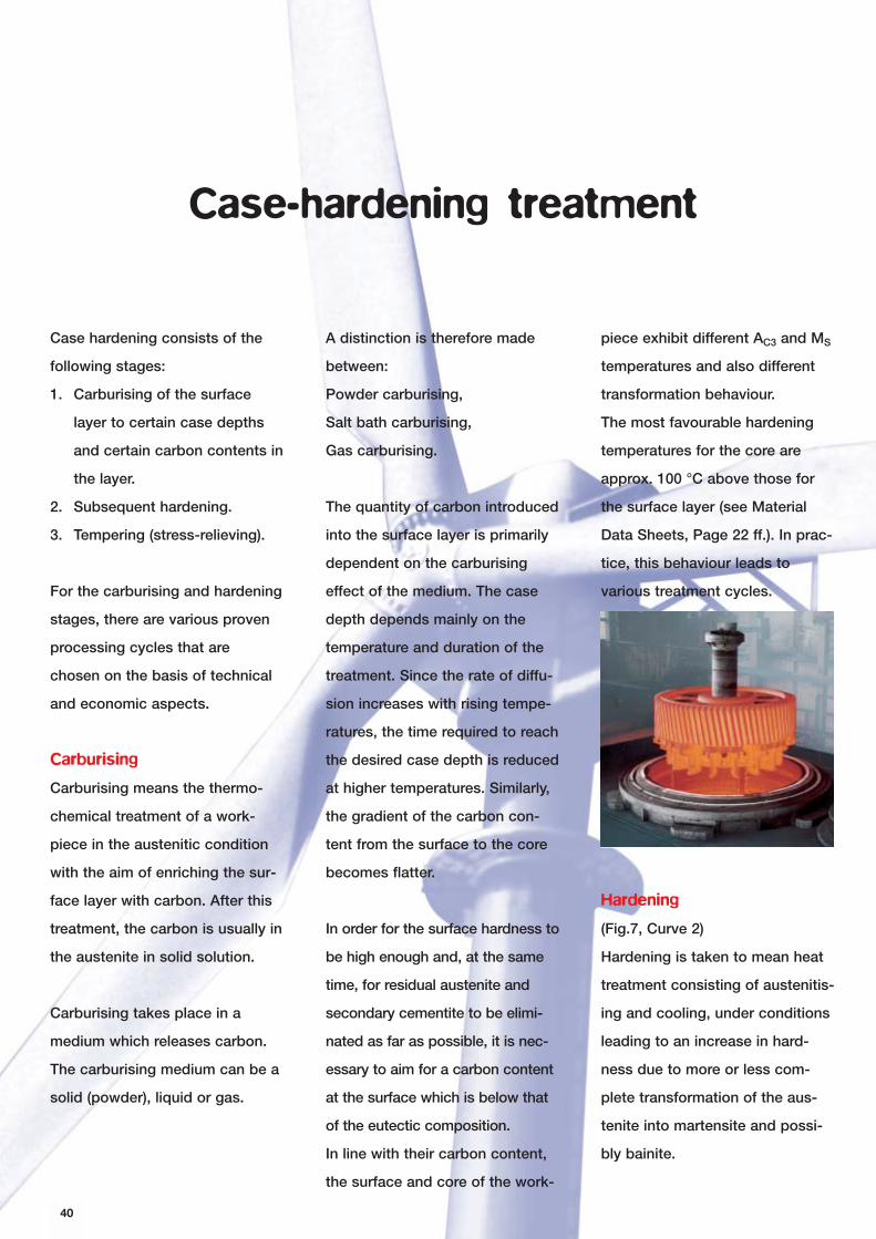
40
Case hardening consists of the
following stages:
1. Carburising of the surface
layer to certain case depths
and certain carbon contents in
the layer.
2. Subsequent hardening.
3. Tempering (stress-relieving).
For the carburising and hardening
stages, there are various proven
processing cycles that are
chosen on the basis of technical
and economic aspects.
Carburising
Carburising means the thermo-
chemical treatment of a work-
piece in the austenitic condition
with the aim of enriching the sur-
face layer with carbon. After this
treatment, the carbon is usually in
the austenite in solid solution.
Carburising takes place in a
medium which releases carbon.
The carburising medium can be a
solid (powder), liquid or gas.
A distinction is therefore made
between:
Powder carburising,
Salt bath carburising,
Gas carburising.
The quantity of carbon introduced
into the surface layer is primarily
dependent on the carburising
effect of the medium. The case
depth depends mainly on the
temperature and duration of the
treatment. Since the rate of diffu-
sion increases with rising tempe-
ratures, the time required to reach
the desired case depth is reduced
at higher temperatures. Similarly,
the gradient of the carbon con-
tent from the surface to the core
becomes flatter.
In order for the surface hardness to
be high enough and, at the same
time, for residual austenite and
secondary cementite to be elimi-
nated as far as possible, it is nec-
essary to aim for a carbon content
at the surface which is below that
of the eutectic composition.
In line with their carbon content,
the surface and core of the work-
Case-hardening treatment
piece exhibit different AC3 and MS
temperatures and also different
transformation behaviour.
The most favourable hardening
temperatures for the core are
approx. 100 °C above those for
the surface layer (see Material
Data Sheets, Page 22 ff.). In prac-
tice, this behaviour leads to
various treatment cycles.
Hardening
(Fig.7, Curve 2)
Hardening is taken to mean heat
treatment consisting of austenitis-
ing and cooling, under conditions
leading to an increase in hard-
ness due to more or less com-
plete transformation of the aus-
tenite into martensite and possi-
bly bainite.
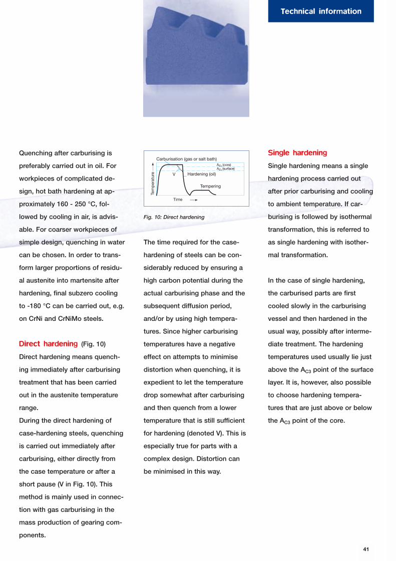
41
Technical information
Quenching after carburising is
preferably carried out in oil. For
workpieces of complicated de-
sign, hot bath hardening at ap-
proximately 160 - 250 °C, fol-
lowed by cooling in air, is advis-
able. For coarser workpieces of
simple design, quenching in water
can be chosen. In order to trans-
form larger proportions of residu-
al austenite into martensite after
hardening, final subzero cooling
to -180 °C can be carried out, e.g.
on CrNi and CrNiMo steels.
Direct hardening (Fig. 10)
Direct hardening means quench-
ing immediately after carburising
treatment that has been carried
out in the austenite temperature
range.
During the direct hardening of
case-hardening steels, quenching
is carried out immediately after
carburising, either directly from
the case temperature or after a
short pause (V in Fig. 10). This
method is mainly used in connec-
tion with gas carburising in the
mass production of gearing com-
ponents.
The time required for the case-
hardening of steels can be con-
siderably reduced by ensuring a
high carbon potential during the
actual carburising phase and the
subsequent diffusion period,
and/or by using high tempera-
tures. Since higher carburising
temperatures have a negative
effect on attempts to minimise
distortion when quenching, it is
expedient to let the temperature
drop somewhat after carburising
and then quench from a lower
temperature that is still sufficient
for hardening (denoted V). This is
especially true for parts with a
complex design. Distortion can
be minimised in this way.
Single hardening
Single hardening means a single
hardening process carried out
after prior carburising and cooling
to ambient temperature. If car-
burising is followed by isothermal
transformation, this is referred to
as single hardening with isother-
mal transformation.
In the case of single hardening,
the carburised parts are first
cooled slowly in the carburising
vessel and then hardened in the
usual way, possibly after interme-
diate treatment. The hardening
temperatures used usually lie just
above the AC3 point of the surface
layer. It is, however, also possible
to choose hardening tempera-
tures that are just above or below
the AC3 point of the core.
Hardening (oil)
Tem
per
atur
e
Carburisation (gas or salt bath)
Tempering
TimeDirect Hardening 10
(core)(surface)
Direkthärten
VAc3
Ac3
Fig. 10: Direct hardening
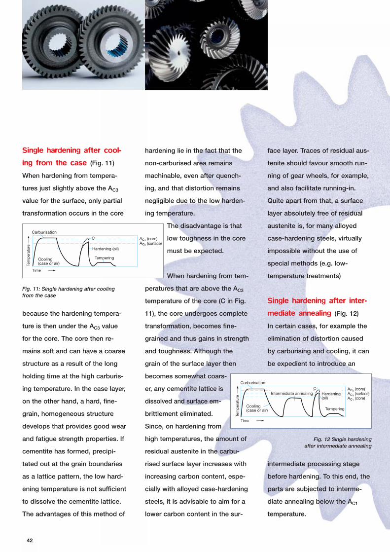
42
Single hardening after cool-
ing from the case (Fig. 11)
When hardening from tempera-
tures just slightly above the AC3
value for the surface, only partial
transformation occurs in the core
because the hardening tempera-
ture is then under the AC3 value
for the core. The core then re-
mains soft and can have a coarse
structure as a result of the long
holding time at the high carburis-
ing temperature. In the case layer,
on the other hand, a hard, fine-
grain, homogeneous structure
develops that provides good wear
and fatigue strength properties. If
cementite has formed, precipi-
tated out at the grain boundaries
as a lattice pattern, the low hard-
ening temperature is not sufficient
to dissolve the cementite lattice.
The advantages of this method of
hardening lie in the fact that the
non-carburised area remains
machinable, even after quench-
ing, and that distortion remains
negligible due to the low harden-
ing temperature.
The disadvantage is that
low toughness in the core
must be expected.
When hardening from tem-
peratures that are above the AC3
temperature of the core (C in Fig.
11), the core undergoes complete
transformation, becomes fine-
grained and thus gains in strength
and toughness. Although the
grain of the surface layer then
becomes somewhat coars-
er, any cementite lattice is
dissolved and surface em-
brittlement eliminated.
Since, on hardening from
high temperatures, the amount of
residual austenite in the carbu-
rised surface layer increases with
increasing carbon content, espe-
cially with alloyed case-hardening
steels, it is advisable to aim for a
lower carbon content in the sur-
face layer. Traces of residual aus-
tenite should favour smooth run-
ning of gear wheels, for example,
and also facilitate running-in.
Quite apart from that, a surface
layer absolutely free of residual
austenite is, for many alloyed
case-hardening steels, virtually
impossible without the use of
special methods (e.g. low-
temperature treatments)
Single hardening after inter-
mediate annealing (Fig. 12)
In certain cases, for example the
elimination of distortion caused
by carburising and cooling, it can
be expedient to introduce an
intermediate processing stage
before hardening. To this end, the
parts are subjected to interme-
diate annealing below the AC1
temperature.
Carburisation
Time
Tem
per
atur
e
Cooling(case or air)
Hardening (oil)
Tempering
(core)(surface)
CAc3
Ac3
Fig. 11: Single hardening after coolingfrom the case
Carburisation
Tem
per
atur
e Hardening(oil)
Cooling(case or air)
Intermediate annealing
Time
Tempering
(core)(surface)(core)
CAc3
Ac3
Ac1
Fig. 12 Single hardening after intermediate annealing
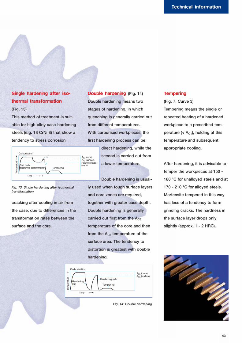
43
Technical information
Single hardening after iso-
thermal transformation
(Fig. 13)
This method of treatment is suit-
able for high-alloy case-hardening
steels (e.g. 18 CrNi 8) that show a
tendency to stress corrosion
cracking after cooling in air from
the case, due to differences in the
transformation rates between the
surface and the core.
Double hardening (Fig. 14)
Double hardening means two
stages of hardening, in which
quenching is generally carried out
from different temperatures.
With carburised workpieces, the
first hardening process can be
direct hardening, while the
second is carried out from
a lower temperature.
Double hardening is usual-
ly used when tough surface layers
and core zones are required,
together with greater case depth.
Double hardening is generally
carried out first from the AC3
temperature of the core and then
from the AC3 temperature of the
surface area. The tendency to
distortion is greatest with double
hardening.
Tempering
(Fig. 7, Curve 3)
Tempering means the single or
repeated heating of a hardened
workpiece to a prescribed tem-
perature (< AC1), holding at this
temperature and subsequent
appropriate cooling.
After hardening, it is advisable to
temper the workpieces at 150 -
180 °C for unalloyed steels and at
170 - 210 °C for alloyed steels.
Martensite tempered in this way
has less of a tendency to form
grinding cracks. The hardness in
the surface layer drops only
slightly (approx. 1 - 2 HRC).
Carburisation
Tem
per
atur
e Hardening (oil)
Salt bathIsothermal transformation
13Single hardening after isothermal transformation
Time
Tempering
(core)(surface)
Pearlite stage(core)
t
CAc3
Ac3
Fig. 13: Single hardening after isothermaltransformation
Carburisation
Tem
per
atur
e
Hardening (oil)
Double hardening4Time
Tempering
(core)(surface)
Hardening(oil)
Ac3
Ac3
Fig. 14: Double hardening
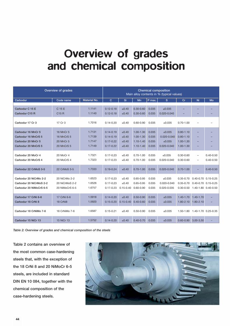
44
Overview of gradesand chemical composition
Table 2 contains an overview of
the most common case-hardening
steels that, with the exception of
the 18 CrNi 8 and 20 NiMoCr 6-5
steels, are included in standard
DIN EN 10 084, together with the
chemical composition of the
case-hardening steels.
Table 2: Overview of grades and chemical composition of the steels
Chemical compositionMain alloy contents in % (typical values)
Carbodur Code name C Si Mn P max. S Cr Ni Mo
Carbodur C 15 E C 15 E 0.12-0.18 ≤0.40 0.30-0.60 0.035 ≤0.035 – – –
Carbodur C15 R C15 R 0.12-0.18 ≤0.40 0.30-0.60 0.035 0.020-0.040 – – –
Carbodur 17 Cr 3 17 Cr 3 0.14-0.20 ≤0.40 0.60-0.90 0.035 ≤0.035 0.70-1.00 – –
Carbodur 16 MnCr 5 16 MnCr 5 0.14-0.19 ≤0.40 1.00-1.30 0.035 ≤0.035 0.80-1.10 – –
Carbodur 16 MnCrS 5 16 MnCrS 5 0.14-0.19 ≤0.40 1.00-1.30 0.035 0.020-0.040 0.80-1.10 – –
Carbodur 20 MnCr 5 20 MnCr 5 0.17-0.22 ≤0.40 1.10-1.40 0.035 ≤0.035 1.00-1.30 – –
Carbodur 20 MnCrS 5 20 MnCrS 5 0.17-0.22 ≤0.40 1.10-1.40 0.035 0.020-0.040 1.00-1.30 – –
Carbodur 20 MoCr 4 20 MoCr 4 0.17-0.23 ≤0.40 0.70-1.00 0.035 ≤0.035 0.30-0.60 – 0.40-0.50
Carbodur 20 MoCrS 4 20 MoCrS 4 0.17-0.23 ≤0.40 0.70-1.00 0.035 0.020-0.040 0.30-0.60 – 0.40-0.50
Carbodur 22 CrMoS 3-5 22 CrMoS 3-5 0.19-0.24 ≤0.40 0.70-1.00 0.035 0.020-0.040 0.70-1.00 – 0.40-0.50
Carbodur 20 NiCrMo 2-2 20 NiCrMo 2-2 0.17-0.23 ≤0.40 0.65-0.95 0.035 ≤0.035 0.35-0.70 0.40-0.70 0.15-0.25
Carbodur 20 NiCrMoS 2-2 20 NiCrMoS 2-2 0.17-0.23 ≤0.40 0.65-0.95 0.035 0.020-0.040 0.35-0.70 0.40-0.70 0.15-0.25
Carbodur 20 NiMoCrS 6-5 20 NiMoCrS 6-5 0.17-0.23 0.15-0.40 0.60-0.90 0.035 0.020-0.035 0.30-0.50 1.40-1.80 0.40-0.50
Carbodur 17 CrNi 6-6 17 CrNi 6-6 0.14-0.20 ≤0.40 0.50-0.90 0.035 ≤0.035 1.40-1.70 1.40-1.70 –
Carbodur 18 CrNi 8 18 CrNi8 0.15-0.20 0.15-0.40 0.40-0.60 0.035 ≤0.035 1.80-2.10 1.80-2.10 –
Carbodur 18 CrNiMo 7-6 18 CrNiMo 7-6 0.15-0.21 ≤0.40 0.50-0.90 0.035 ≤0.035 1.50-1.80 1.40-1.70 0.25-0.35
Carbodur 15 NiCr 13 15 NiCr 13 0.14-0.20 ≤0.40 0.40-0.70 0.035 ≤0.035 0.60-0.90 3,00-3,50 –
Overview of grades
Material No.
1.1141
1.1140
1.7016
1.7131
1.7139
1.7147
1.7149
1.7321
1.7323
1.7333
1.6523
1.6526
1.6757
1.5918
1.5920
1.6587
1.5752
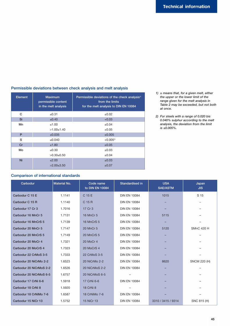
45
Technical information
C ≤0.31 ±0.02
Si ≤0.40 +0.03
Mn ≤1.00 ±0.04
>1.00≤1.40 ±0.05
P ≤0.035 ±0.005
S ≤0.040 +0.0052)
Cr ≤1.80 ±0.05
Mo ≤0.30 ±0.03
>0.30≤0.50 ±0.04
Ni ≤2.00 ±0.03
>2.00≤3.50 ±0.07
Element Maximum
permissible content
in the melt analysis
Permissible deviations of the check analysis1)
from the limits
for the melt analysis to DIN EN 10084
1) ± means that, for a given melt, either the upper or the lower limit of the range given for the melt analysis in Table 2 may be exceeded, but not bothat once.
2) For steels with a range of 0.020 bis 0.040% sulphur according to the meltanalysis, the deviation from the limitis ±0.005%.
Carbodur Material No. Code name
to DIN EN 10084
Standardised in USA
SAE/ASTM
Japan
JIS
Permissible deviations between check analysis and melt analysis
Comparison of international standards
Carbodur C 15 E 1.1141 C 15 E DIN EN 10084 1015 S 15
Carbodur C 15 R 1.1140 C 15 R DIN EN 10084 – –
Carbodur 17 Cr 3 1.7016 17 Cr 3 DIN EN 10084 – –
Carbodur 16 MnCr 5 1.7131 16 MnCr 5 DIN EN 10084 5115 –
Carbodur 16 MnCrS 5 1.7139 16 MnCrS 5 DIN EN 10084 – –
Carbodur 20 MnCr 5 1.7147 20 MnCr 5 DIN EN 10084 5120 SMnC 420 H
Carbodur 20 MnCrS 5 1.7149 20 MnCrS 5 DIN EN 10084 – –
Carbodur 20 MoCr 4 1.7321 20 MoCr 4 DIN EN 10084 – –
Carbodur 20 MoCrS 4 1.7323 20 MoCrS 4 DIN EN 10084 – –
Carbodur 22 CrMoS 3-5 1.7333 22 CrMoS 3-5 DIN EN 10084 – –
Carbodur 20 NiCrMo 2-2 1.6523 20 NiCrMo 2-2 DIN EN 10084 8620 SNCM 220 (H)
Carbodur 20 NiCrMoS 2-2 1.6526 20 NiCrMoS 2-2 DIN EN 10084 – –
Carbodur 20 NiCrMoS 6-5 1.6757 20 NiCrMoS 6-5 – – –
Carbodur 17 CrNi 6-6 1.5918 17 CrNi 6-6 DIN EN 10084 – –
Carbodur 18 CrNi 8 1.5920 18 CrNi 8 – – –
Carbodur 18 CrNiMo 7-6 1.6587 18 CrNiMo 7-6 DIN EN 10084 – –
Carbodur 15 NiCr 13 1.5752 15 NiCr 13 DIN EN 10084 3310 / 3415 / 9314 SNC 815 (H)
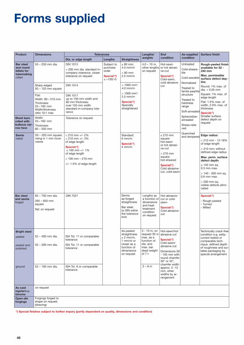
46
Forms supplied
55 – 250 mm dia.
Sharp-edged50 – 103 mm square
DIN 1014
DIN 7527
DIN 1013
> 200 mm dia. standard in-company tolerance, closertolerance on request
Subject topurchaseorder
Special:*)≤ +100/-0
Flat:Width: 80 – 510 mmThickness: 25 – 160 mmWidth/thickness ratio 10:1 max
Width: 25 – 160 mm
Thickness:80 – 550 mm
65 – 750 mm dia.
265 – 650 mm square
flat: on request
50 – 320 mm square,rising in 1 mm incre-ments
52 – 400 mm dia.
52 – 300 mm dia.
DIN 1017up to 150 mm width and 60 mm thickness;over 150 mm widthstandard in-company tole-rance
Tolerance on request
< 210 mm +/- 2%> 210 mm +/- 3%of edge length
Special:*)≤ 100 mm +/- 1%
of edge length
> 100 mm – 210 mm
+/- 1.5% of edge length
ISA Tol. 11 or comparabletolerance
ISA Tol. 11 or comparabletolerance
ISA-Tol. 8 or comparable tolerance
≤ 80 mm: 4.0 mm/m
> 80 mm: 2.5 mm/m
4.0 – 10 m,other lengthson request
Lengths as a function ofdimensionsand heat-treatmentcondition on request
3 - 10 m, onrequest 30 mmax. as afunction ofdia. andmax. bardead weightof 7 t
Hot-sawn or hot abrasi-ve-cut
Special:*)Cold-sawn,cold abrasive-cut
Hot abrasive-cut or cold-sawn
Special:*)Cold abrasive-cut
≤ 210 mm square:hot-sawn or hot abrasi-ve-cut
> 210 mm square:hot-sheared
Special:*)Cold abrasive-cut, cold-sawn
Hot-sawn/hotabrasive-cut
Special:*)Cold-sawn/abrasive-cut
Dimensions 50- 105 mm withround chamfer30° or 45°,chamfer widthapprox. 5 -12mm, otherwidths by ar-rangement
Rough-peeled finishavailable for 52 -240 mm
Max. permissiblesurface defect dep-ths:
Round: 1% max. ofdia. + 0.05 mm
Square: 1% max. ofedge length
Flat: 1.5% max. ofwidth, 2.0% max. ofthickness
Special:*)Smaller surfacedefect depth onrequest
Special:*)
- Rough-peeled- Turned- Milled
Edge radius:
< 210 mm - 12-18%of edge length
> 210 mm: withoutdefined edge radius
Max. perm. surfacedefect depth:
≤ 140 mm sq.0.3 mm max.
> 140 - 200 mm sq.0.6 mm max.
> 200 mm sq.visible defects elimi-nated
Technically crack-freecondition e.g. eddy-current tested orcomparable tech-nique, defined depthof roughness and sui-table packaging byspecial arrangement
< 1000 mm2:4.0 mm/m
> 1000 mm2:2.5 mm/m
Special:*)Speciallystraightened
Standard: 6 mm/m
Special:*)4 mm/m
As-peeledstraightness ≤ 2 mm/m, 1 mm/m orcloser as afunction ofdimensions on request
Untreated
Cold-sheara-ble
Cold-sawable
Normalized
Treated toferrite-pearlitestructure
Treated tohardnessrange
Soft-annealed
Spheroidize-annealed
Stress-relie-ved
Quenchedand tempered
Bar steeland roundbillets fortubemakingrolled
Sheet barsrolled withbulbous nar-row face
Bar steeland semis forged
Semisrolled
Bright steel
peeled
peeled andpolished
*) Special finishes subject to further inquiry (partly dependent on quality, dimensions and condition)
ground 52 – 100 mm dia.
Semis:as-forgedstraightness
Bar steel:to DIN withinthe tolerancelimit
3 – 8 m
Surface finishAs-suppliedcondition
End condition
Lengths/weightsStraightnessLengthsDia. or edge length
TolerancesProduct Dimensions
on requestAs-castingots/c.c.blooms Open-dieforgings
Forgings forged toshape on request(drawing)

47
Hardness comparison table
Tensile strength, Brinell, Vickers and Rockwell hardness
Tensilestrength
RmN/mm2
Ball inden-tation mm
d HB
Brinell hardness Vickershardness
HV
Rockwell hardness
HRB HRC HR 30 N
255 6.63 76.0 80 – – –270 6.45 80.7 85 41.0 – –285 6.30 85.5 90 48.0 – –305 6.16 90.2 95 52.0 – –320 6.01 95.0 100 56.2 – –335 5.90 99.8 105 – – –350 5.75 105 110 62.3 – –370 5.65 109 115 – – –385 5.54 114 120 66.7 – –400 5.43 119 125 – – –415 5.33 124 130 71.2 – –430 5.26 128 135 – – –450 5.16 133 140 75.0 – –465 5.08 138 145 – – –480 4.99 143 150 78.7 – –495 4.93 147 155 – – –510 4.85 152 160 81.7 – –530 4.79 156 165 – – –545 4.71 162 170 85.0 – –560 4.66 166 175 – – –575 4.59 171 180 87.1 – –595 4.53 176 185 – – –610 4.47 181 190 89.5 – –625 4.43 185 195 – – –640 4.37 190 200 91.5 – –660 4.32 195 205 92.5 – –675 4.27 199 210 93.5 – –690 4.22 204 215 94.0 – –705 4.18 209 220 95.0 – –720 4.13 214 225 96.0 – –740 4.08 219 230 96.7 – –755 4.05 223 235 – – –770 4.01 228 240 98.1 20.3 41.7785 3.97 233 245 – 21.3 42.5800 3.92 238 250 99.5 22.2 43.4820 3.89 242 255 – 23.1 44.2835 3.86 247 260 (101) 24.0 45.0850 3.82 252 265 – 24.8 45.7865 3.78 257 270 (102) 25.6 46.4880 3.75 261 275 – 26.4 47.2900 3.72 266 280 (104) 27.1 47.8915 3.69 271 285 – 27.8 48.4930 3.66 276 290 (105) 28.5 49.0950 3.63 280 295 – 29.2 49.7965 3.60 285 300 – 29.8 50.2995 3.54 295 310 – 31.0 51.3
1030 3.49 304 320 – 32.2 52.31060 3.43 314 330 – 33.3 53.61095 3.39 323 340 – 34.4 54.41125 3.34 333 350 – 35.5 55.41155 3.29 342 360 – 36.6 56.41190 3.25 352 370 – 37.7 57.41220 3.21 361 380 – 38.8 58.41255 3.17 371 390 – 39.8 59.31290 3.13 380 400 – 40.8 60.21320 3.09 390 410 – 41.8 61.11350 3.06 399 420 – 42.7 61.91385 3.02 409 430 – 43.6 62.71420 2.99 418 440 – 44.5 63.51455 2.95 428 450 – 45.3 64.31485 2.92 437 460 – 46.1 64.91520 2.89 447 470 – 46.9 65.71555 2.86 (456) 480 – 47.7 66.41595 2.83 (466) 490 – 48.4 67.11630 2.81 (475) 500 – 49.1 67.71665 2.78 (485) 510 – 49.8 68.31700 2.75 (494) 520 – 50.5 69.01740 2.73 (504) 530 – 51.1 69.51775 2.70 (513) 540 – 51.7 70.01810 2.68 (523) 550 – 52.3 70.51845 2.66 (532) 560 – 53.0 71.21880 2.63 (542) 570 – 53.6 71.71920 2.60 (551) 580 – 54.1 72.11955 2.59 (561) 590 – 54.7 72.71995 2.57 (570) 600 – 55.2 73.2
Tensilestrength
RmN/mm2
Ballindentation
mm d HB
Brinell hardness Vickershardness
HV
Rockwell hardness
HRB HRC HR 30 N
2030 2.54 (580) 610 – 55.7 73.72070 2.52 (589) 620 – 56.3 74.22105 2.51 (599) 630 – 56.8 74.62145 2.49 (608) 640 – 57.3 75.12180 2.47 (618) 650 – 57.8 75.5
– – – 660 – 58.3 75.9– – – 670 – 58.8 76.4– – – 680 – 59.2 76.8– – – 690 – 59.7 77.2– – – 700 – 60.1 77.6– – – 720 – 61.0 78.4– – – 740 – 61.8 79.1– – – 760 – 62.5 79.7– – – 780 – 63.3 80.4– – – 800 – 64.0 81.1– – – 820 – 64.7 81.7– – – 840 – 65.3 82.2– – – 860 – 65.9 82.7– – – 880 – 66.4 83.1– – – 900 – 67.0 83.6– – – 920 – 67.5 84.0– – – 940 – 68.0 84.4
Tensile strength N/mm2 Rm
Brinell hardness1) Diameter of the d1) Calculated from: ball indentation in mm
HB = 0.95 · HV
(0.102 F/D2 = 30) Hardness HBD = 10 value =
Vickers hardness Diamond pyramid HVTest forces ≥ 50 N
Rockwell hardness Ball 1.588 mm (1/16“) HRBTotal test force = 98 N
Diamond cone HRCTotal test force = 1471 N
Diamond coneTotal test force = 294 N HR 30 N
0.102 · 2 Fπ D (D – √D2 – d2)
Conversions of hardness values using this conversion table are only approximate.See DIN 50 150, December 1976.
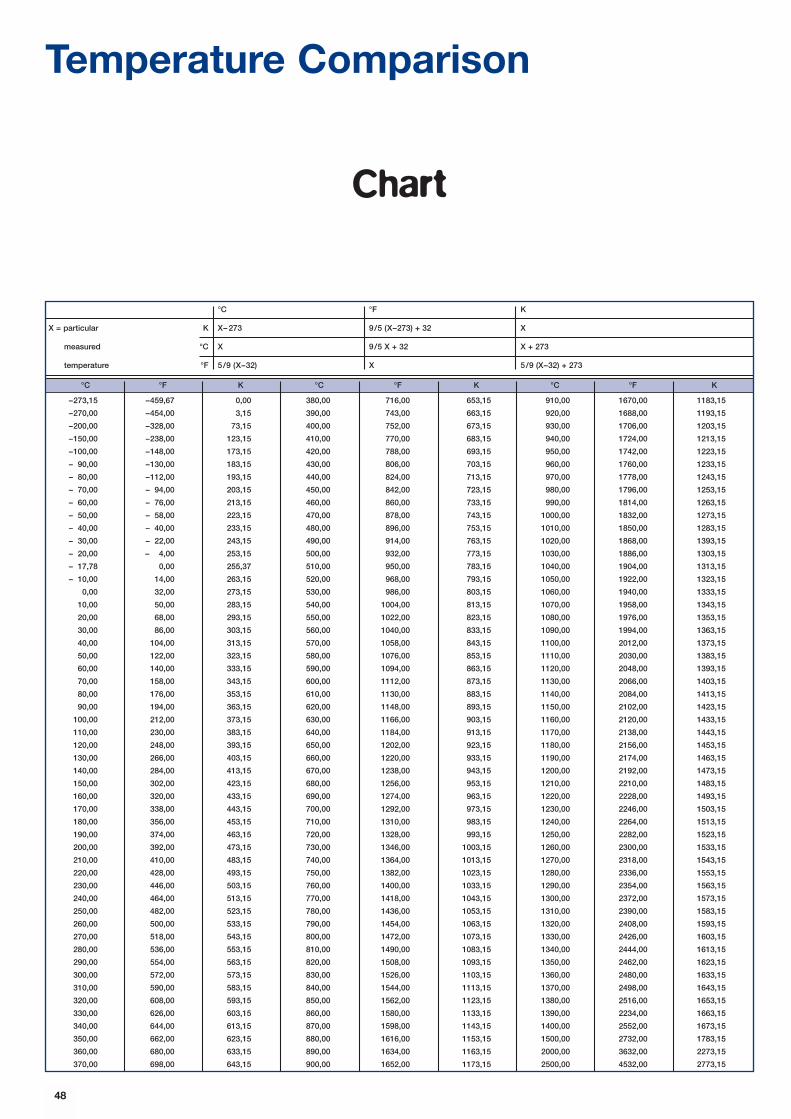
Temperature Comparison
Chart
°C °F K °C °F K °C °F K
–273,15 –459,67 0,00 380,00 716,00 653,15 910,00 1670,00 1183,15
–270,00 –454,00 3,15 390,00 743,00 663,15 920,00 1688,00 1193,15
–200,00 –328,00 73,15 400,00 752,00 673,15 930,00 1706,00 1203,15
–150,00 –238,00 123,15 410,00 770,00 683,15 940,00 1724,00 1213,15
–100,00 –148,00 173,15 420,00 788,00 693,15 950,00 1742,00 1223,15
– 90,00 –130,00 183,15 430,00 806,00 703,15 960,00 1760,00 1233,15
– 80,00 –112,00 193,15 440,00 824,00 713,15 970,00 1778,00 1243,15
– 70,00 – 94,00 203,15 450,00 842,00 723,15 980,00 1796,00 1253,15
– 60,00 – 76,00 213,15 460,00 860,00 733,15 990,00 1814,00 1263,15
– 50,00 – 58,00 223,15 470,00 878,00 743,15 1000,00 1832,00 1273,15
– 40,00 – 40,00 233,15 480,00 896,00 753,15 1010,00 1850,00 1283,15
– 30,00 – 22,00 243,15 490,00 914,00 763,15 1020,00 1868,00 1393,15
– 20,00 – 4,00 253,15 500,00 932,00 773,15 1030,00 1886,00 1303,15
– 17,78 0,00 255,37 510,00 950,00 783,15 1040,00 1904,00 1313,15
– 10,00 14,00 263,15 520,00 968,00 793,15 1050,00 1922,00 1323,15
0,00 32,00 273,15 530,00 986,00 803,15 1060,00 1940,00 1333,15
10,00 50,00 283,15 540,00 1004,00 813,15 1070,00 1958,00 1343,15
20,00 68,00 293,15 550,00 1022,00 823,15 1080,00 1976,00 1353,15
30,00 86,00 303,15 560,00 1040,00 833,15 1090,00 1994,00 1363,15
40,00 104,00 313,15 570,00 1058,00 843,15 1100,00 2012,00 1373,15
50,00 122,00 323,15 580,00 1076,00 853,15 1110,00 2030,00 1383,15
60,00 140,00 333,15 590,00 1094,00 863,15 1120,00 2048,00 1393,15
70,00 158,00 343,15 600,00 1112,00 873,15 1130,00 2066,00 1403,15
80,00 176,00 353,15 610,00 1130,00 883,15 1140,00 2084,00 1413,15
90,00 194,00 363,15 620,00 1148,00 893,15 1150,00 2102,00 1423,15
100,00 212,00 373,15 630,00 1166,00 903,15 1160,00 2120,00 1433,15
110,00 230,00 383,15 640,00 1184,00 913,15 1170,00 2138,00 1443,15
120,00 248,00 393,15 650,00 1202,00 923,15 1180,00 2156,00 1453,15
130,00 266,00 403,15 660,00 1220,00 933,15 1190,00 2174,00 1463,15
140,00 284,00 413,15 670,00 1238,00 943,15 1200,00 2192,00 1473,15
150,00 302,00 423,15 680,00 1256,00 953,15 1210,00 2210,00 1483,15
160,00 320,00 433,15 690,00 1274,00 963,15 1220,00 2228,00 1493,15
170,00 338,00 443,15 700,00 1292,00 973,15 1230,00 2246,00 1503,15
180,00 356,00 453,15 710,00 1310,00 983,15 1240,00 2264,00 1513,15
190,00 374,00 463,15 720,00 1328,00 993,15 1250,00 2282,00 1523,15
200,00 392,00 473,15 730,00 1346,00 1003,15 1260,00 2300,00 1533,15
210,00 410,00 483,15 740,00 1364,00 1013,15 1270,00 2318,00 1543,15
220,00 428,00 493,15 750,00 1382,00 1023,15 1280,00 2336,00 1553,15
230,00 446,00 503,15 760,00 1400,00 1033,15 1290,00 2354,00 1563,15
240,00 464,00 513,15 770,00 1418,00 1043,15 1300,00 2372,00 1573,15
250,00 482,00 523,15 780,00 1436,00 1053,15 1310,00 2390,00 1583,15
260,00 500,00 533,15 790,00 1454,00 1063,15 1320,00 2408,00 1593,15
270,00 518,00 543,15 800,00 1472,00 1073,15 1330,00 2426,00 1603,15
280,00 536,00 553,15 810,00 1490,00 1083,15 1340,00 2444,00 1613,15
290,00 554,00 563,15 820,00 1508,00 1093,15 1350,00 2462,00 1623,15
300,00 572,00 573,15 830,00 1526,00 1103,15 1360,00 2480,00 1633,15
310,00 590,00 583,15 840,00 1544,00 1113,15 1370,00 2498,00 1643,15
320,00 608,00 593,15 850,00 1562,00 1123,15 1380,00 2516,00 1653,15
330,00 626,00 603,15 860,00 1580,00 1133,15 1390,00 2234,00 1663,15
340,00 644,00 613,15 870,00 1598,00 1143,15 1400,00 2552,00 1673,15
350,00 662,00 623,15 880,00 1616,00 1153,15 1500,00 2732,00 1783,15
360,00 680,00 633,15 890,00 1634,00 1163,15 2000,00 3632,00 2273,15
370,00 698,00 643,15 900,00 1652,00 1173,15 2500,00 4532,00 2773,15
°C °F K
X = particular K X– 273 9/5 (X–273) + 32 X
measured °C X 9/5 X + 32 X + 273
temperature °F 5/9 (X–32) X 5/9 (X–32) + 273
48

50
Page Source Object/Motif
Cover Bavaria Gear wheel03 Lohmann + Stolterfoth Planetary gear04 Steinmetz Team meeting4 – 5 Sauter, Bachmann Spiral bevel gears4 Sauter, Bachmann Set of gears5 Sauter, Bachmann Precision worm
Company photo Micrograph6 – 7 ATA-GEARS Hardening of a ring gear7 Company photo Steel bars7 Steinmetz Chips8 CarboTech Cutting drum
Bavaria Hydroelectric power station8 – 9 Lohmann + Stolterfoth Planetary gear8 ATA-GEARS Spiral bevel gears9 Image Drilling rig
Bavaria Wind turbine generatorsSchreiber/Flender Gears for wind turbine generatorFrese Gear wheel
10 Schuster AirbusBavaria Formula 1 racecar
10 – 11 ATA-GEARS Ring gear with pinion10 Company photo/Flender Set of gears
11 DAF XF95 truck VW VW GolfImagine Oil tankerMAAG Gear Marine gearCompany photo Cable car
12 Company photo Printing pressLohmann + Stolterfoth Parabolic reflector
12 – 13 Company photo/Flender Set of gears12 Lohmann + Stolterfoth Gear wheels for combing cylinder gear13 Company photo Crane truck
Company photo Wheel loaderImagine Ariane rocketCompany photo/Flender Gear detail
14 Steinmetz Sawing of disksSteinmetz Disks with and without drilled holeSteinmetz Steel bars
15 Lohmann + Stolterfoth Ground gear wheels16 Company photo Electric arc furnace17 Company photo Continuous casting plant
Company photo ESR plant18 Company photo Forged steel bars
Company photo Peeling of steel bars18 – 19 Company photo Forging of steel bars
Company photo Sawing of steel barsSteinmetz Disks with drilled hole
36 Sauter, Bachmann Spiral bevel gears40 Lohmann + Stolterfoth Case hardening of a large wheel42 Lohmann + Stolterfoth Ground gear wheels
ATA-GEARS Spiral bevel gears43 Frese Gear wheel44 Lohmann + Stolterfoth Gear wheels for combing cylinder gear48 – 49 Lohmann + Stolterfoth Planetary gear
Photos

51
General note (liability)
All statements regarding the properties
or utilisation of the materials or products
mentioned are for the purposes of
description only. Guarantees regarding
the existence of certain properties or a
certain utilisation are only ever valid if
agreed upon in writing.

CARBODURCARBODUR
CARBODUR
EDELSTAHL WITTEN-KREFELD GMBHAuestrasse 4, D-58452 Witten · Tel. (+49) 23 02 / 29 43 07 · Telefax (+49) 2302 / 29 43 08
E-mail: [email protected] · Internet: www.edelstahl-witten-krefeld.de
• Sales - Case-hardening steelsTel. (+49) 23 02/29 43 46 · Telefax (+49) 23 02/29 46 87E-mail: [email protected]
• Quality DepartmentTel. (+49) 23 02/29 40 20 · Telefax (+49) 23 02/29 44 36Tel. (+49) 21 51/83 20 46 · Telefax (+49) 21 51/83 41 56
Case-hardening steels
CARBODURCARBODUR
CARBODUR
7/99
Ec
THYROFORTTHYROFORT
THYROFORT
Special engineer ing steels
EDELSTAHL WITTEN-KREFELD GMBH
Heat-treatable steels
THYROFORTTHYROFORT
THYROFORT

3
ContentsPage 4 – 5 General
Page 6 – 7 Special features
Page 8 – 9 Steel portraits
Page 10 – 13 Application examples
Page 14 – 15 Steel production
Page 16 – 17 Steel processing
Technical information
Page 18 – 20 Overview of grades and chemical composition
Page 21 – 22 Minimum yield points and tensile strength ranges
Material data
Page 24 – 65 Material data sheets
Technical information
Page 66 – 68 Thyrofort – The basics
Page 69 – 70 Heat treatment – Schematic representation
Page 71 Sampling according to DIN EN 10083
Page 72 – 73 Ruling heat treatment diameter
Page 74 Comparison of international standards
Page 75 Hardness comparison table
Page 76 Forms supplied
Page 77 Temperature Comparison
Page 78 List of photos
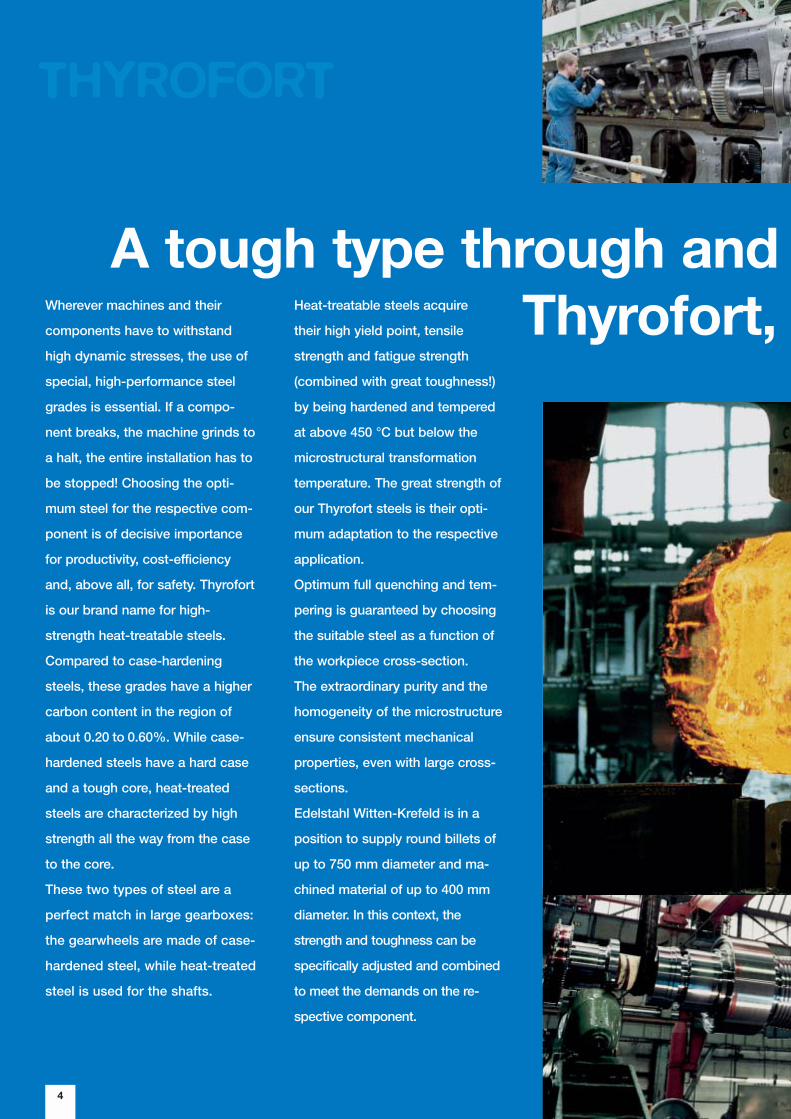
Wherever machines and their
components have to withstand
high dynamic stresses, the use of
special, high-performance steel
grades is essential. If a compo-
nent breaks, the machine grinds to
a halt, the entire installation has to
be stopped! Choosing the opti-
mum steel for the respective com-
ponent is of decisive importance
for productivity, cost-efficiency
and, above all, for safety. Thyrofort
is our brand name for high-
strength heat-treatable steels.
Compared to case-hardening
steels, these grades have a higher
carbon content in the region of
about 0.20 to 0.60%. While case-
hardened steels have a hard case
and a tough core, heat-treated
steels are characterized by high
strength all the way from the case
to the core.
These two types of steel are a
perfect match in large gearboxes:
the gearwheels are made of case-
hardened steel, while heat-treated
steel is used for the shafts.
4
Heat-treatable steels acquire
their high yield point, tensile
strength and fatigue strength
(combined with great toughness!)
by being hardened and tempered
at above 450 °C but below the
microstructural transformation
temperature. The great strength of
our Thyrofort steels is their opti-
mum adaptation to the respective
application.
Optimum full quenching and tem-
pering is guaranteed by choosing
the suitable steel as a function of
the workpiece cross-section.
The extraordinary purity and the
homogeneity of the microstructure
ensure consistent mechanical
properties, even with large cross-
sections.
Edelstahl Witten-Krefeld is in a
position to supply round billets of
up to 750 mm diameter and ma-
chined material of up to 400 mm
diameter. In this context, the
strength and toughness can be
specifically adjusted and combined
to meet the demands on the re-
spective component.
THYROFORT
A tough type through and Thyrofort,

5
Thyrofort heat-treatable steels
offer excellent hot formability.
Cold formability and machinability
are dependent on the carbon con-
tent and the crystalline structure.
Appropriate alloying and heat
treatment permit adjustment of
the microstructure for optimum
machinability.
The top quality of Thyrofort steels
is achieved through high process
reliability and modern installations
for melting, highly developed sec-
ondary metallurgy, vertical contin-
uous casting, remelting, hot
forming and modern test facilities.
Edelstahl Witten-Krefeld is in a
position to offer you a tailor-made
heat-treatable steel for every
application and every component.
Ask our material specialists for
advice.
Thyrofort – designed for
extraordinary stresses
through -if you have big things in mind
General
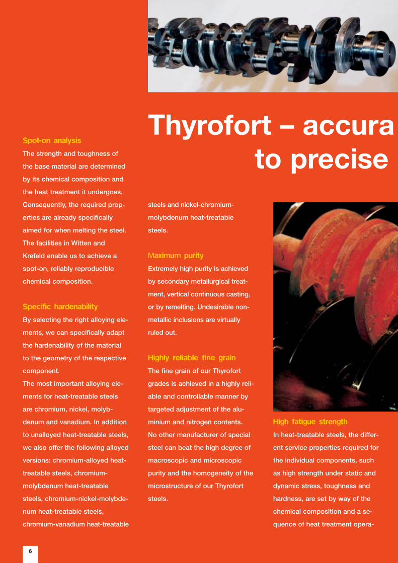
High fatigue strength
In heat-treatable steels, the differ-
ent service properties required for
the individual components, such
as high strength under static and
dynamic stress, toughness and
hardness, are set by way of the
chemical composition and a se-
quence of heat treatment opera-
Spot-on analysis
The strength and toughness of
the base material are determined
by its chemical composition and
the heat treatment it undergoes.
Consequently, the required prop-
erties are already specifically
aimed for when melting the steel.
The facilities in Witten and
Krefeld enable us to achieve a
spot-on, reliably reproducible
chemical composition.
Specific hardenability
By selecting the right alloying ele-
ments, we can specifically adapt
the hardenability of the material
to the geometry of the respective
component.
The most important alloying ele-
ments for heat-treatable steels
are chromium, nickel, molyb-
denum and vanadium. In addition
to unalloyed heat-treatable steels,
we also offer the following alloyed
versions: chromium-alloyed heat-
treatable steels, chromium-
molybdenum heat-treatable
steels, chromium-nickel-molybde-
num heat-treatable steels,
chromium-vanadium heat-treatable
6
steels and nickel-chromium-
molybdenum heat-treatable
steels.
Maximum purity
Extremely high purity is achieved
by secondary metallurgical treat-
ment, vertical continuous casting,
or by remelting. Undesirable non-
metallic inclusions are virtually
ruled out.
Highly reliable fine grain
The fine grain of our Thyrofort
grades is achieved in a highly reli-
able and controllable manner by
targeted adjustment of the alu-
minium and nitrogen contents.
No other manufacturer of special
steel can beat the high degree of
macroscopic and microscopic
purity and the homogeneity of the
microstructure of our Thyrofort
steels.
Thyrofort – accurato precise

7
tely adaptedrequirements
tions. Additional surface harden-
ing by inductive heating increases
the wear resistance.
Good machinability
The larger the quantity of compo-
nents to be manufactured, the
more important it is for the materi-
al to have good machinability. This
means the cost-effectiveness of
series production is already partly
determined when ordering a spe-
cific steel grade.
The machinability of heat-treated
steels is influenced by the
microstructure, the strength and
the non-metallic inclusions (sul-
phides, oxides).
Further optimisation of the
machinability can be achieved
through increasing the level of
sulphidic inclusions, by calcium
treatment and by heat treatment,
i.e. by specifically adjusting the
microstructure.
Customised heat treatment
Depending on the envisaged ap-
plication and processing, we can
supply you with Thyrofort steel
grades in a wide variety of treated
conditions, e.g. with reduced
hardness or within a given
strength range.
Detailed technical information on
as-delivered conditions and pro-
cessing can be found starting on
Page 66.
Special features
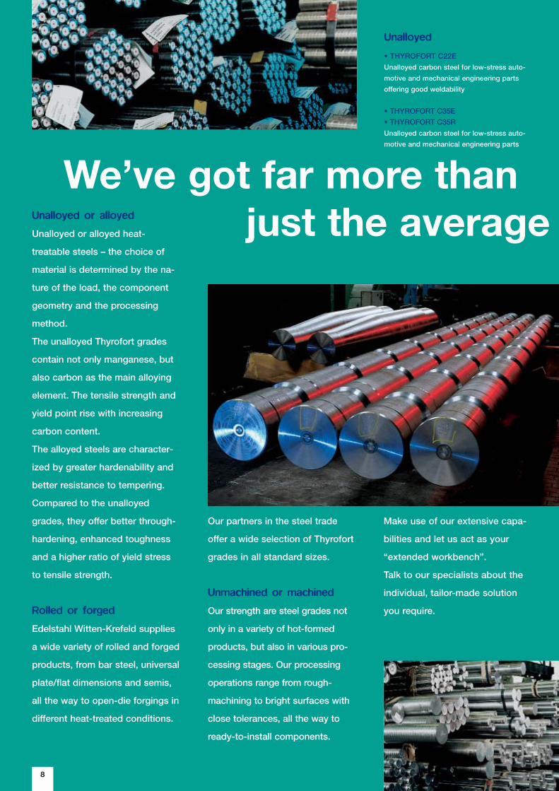
8
We’ve got far more thanjust the averageUnalloyed or alloyed
Unalloyed or alloyed heat-
treatable steels – the choice of
material is determined by the na-
ture of the load, the component
geometry and the processing
method.
The unalloyed Thyrofort grades
contain not only manganese, but
also carbon as the main alloying
element. The tensile strength and
yield point rise with increasing
carbon content.
The alloyed steels are character-
ized by greater hardenability and
better resistance to tempering.
Compared to the unalloyed
grades, they offer better through-
hardening, enhanced toughness
and a higher ratio of yield stress
to tensile strength.
Rolled or forged
Edelstahl Witten-Krefeld supplies
a wide variety of rolled and forged
products, from bar steel, universal
plate/flat dimensions and semis,
all the way to open-die forgings in
different heat-treated conditions.
Our partners in the steel trade
offer a wide selection of Thyrofort
grades in all standard sizes.
Unmachined or machined
Our strength are steel grades not
only in a variety of hot-formed
products, but also in various pro-
cessing stages. Our processing
operations range from rough-
machining to bright surfaces with
close tolerances, all the way to
ready-to-install components.
Unalloyed
• THYROFORT C22EUnalloyed carbon steel for low-stress auto-
motive and mechanical engineering parts
offering good weldability
• THYROFORT C35E• THYROFORT C35RUnalloyed carbon steel for low-stress auto-
motive and mechanical engineering parts
Make use of our extensive capa-
bilities and let us act as your
“extended workbench”.
Talk to our specialists about the
individual, tailor-made solution
you require.
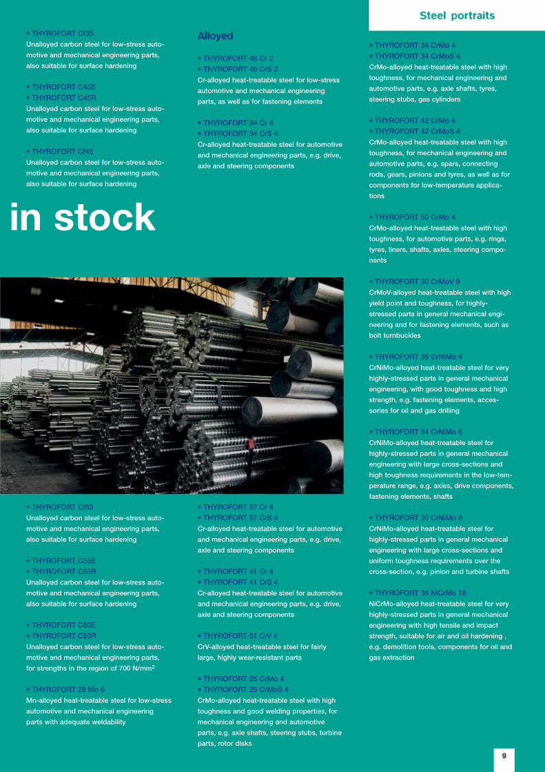
9
in stock
• THYROFORT Cf35Unalloyed carbon steel for low-stress auto-
motive and mechanical engineering parts,
also suitable for surface hardening
• THYROFORT C45E• THYROFORT C45RUnalloyed carbon steel for low-stress auto-
motive and mechanical engineering parts,
also suitable for surface hardening
• THYROFORT Cf45Unalloyed carbon steel for low-stress auto-
motive and mechanical engineering parts,
also suitable for surface hardening
• THYROFORT Cf53Unalloyed carbon steel for low-stress auto-
motive and mechanical engineering parts,
also suitable for surface hardening
• THYROFORT C55E• THYROFORT C55RUnalloyed carbon steel for low-stress auto-
motive and mechanical engineering parts,
also suitable for surface hardening
• THYROFORT C60E• THYROFORT C60RUnalloyed carbon steel for low-stress auto-
motive and mechanical engineering parts,
for strengths in the region of 700 N/mm2
• THYROFORT 28 Mn 6Mn-alloyed heat-treatable steel for low-stress
automotive and mechanical engineering
parts with adequate weldability
Alloyed
• THYROFORT 46 Cr 2• THYROFORT 46 CrS 2Cr-alloyed heat-treatable steel for low-stress
automotive and mechanical engineering
parts, as well as for fastening elements
• THYROFORT 34 Cr 4• THYROFORT 34 CrS 4Cr-alloyed heat-treatable steel for automotive
and mechanical engineering parts, e.g. drive,
axle and steering components
• THYROFORT 34 CrMo 4• THYROFORT 34 CrMoS 4CrMo-alloyed heat-treatable steel with high
toughness, for mechanical engineering and
automotive parts, e.g. axle shafts, tyres,
steering stubs, gas cylinders
• THYROFORT 42 CrMo 4• THYROFORT 42 CrMoS 4CrMo-alloyed heat-treatable steel with high
toughness, for mechanical engineering and
automotive parts, e.g. spars, connecting
rods, gears, pinions and tyres, as well as for
components for low-temperature applica-
tions
• THYROFORT 50 CrMo 4CrMo-alloyed heat-treatable steel with high
toughness, for automotive parts, e.g. rings,
tyres, liners, shafts, axles, steering compo-
nents
• THYROFORT 30 CrMoV 9CrMoV-alloyed heat-treatable steel with high
yield point and toughness, for highly-
stressed parts in general mechanical engi-
neering and for fastening elements, such as
bolt turnbuckles
• THYROFORT 36 CrNiMo 4CrNiMo-alloyed heat-treatable steel for very
highly-stressed parts in general mechanical
engineering, with good toughness and high
strength, e.g. fastening elements, acces-
sories for oil and gas drilling
• THYROFORT 34 CrNiMo 6CrNiMo-alloyed heat-treatable steel for
highly-stressed parts in general mechanical
engineering with large cross-sections and
high toughness requirements in the low-tem-
perature range, e.g. axles, drive components,
fastening elements, shafts
• THYROFORT 30 CrNiMo 8CrNiMo-alloyed heat-treatable steel for
highly-stressed parts in general mechanical
engineering with large cross-sections and
uniform toughness requirements over the
cross-section, e.g. pinion and turbine shafts
• THYROFORT 36 NiCrMo 16NiCrMo-alloyed heat-treatable steel for very
highly-stressed parts in general mechanical
engineering with high tensile and impact
strength, suitable for air and oil hardening ,
e.g. demolition tools, components for oil and
gas extraction
• THYROFORT 37 Cr 4• THYROFORT 37 CrS 4Cr-alloyed heat-treatable steel for automotive
and mechanical engineering parts, e.g. drive,
axle and steering components
• THYROFORT 41 Cr 4• THYROFORT 41 CrS 4Cr-alloyed heat-treatable steel for automotive
and mechanical engineering parts, e.g. drive,
axle and steering components
• THYROFORT 51 CrV 4CrV-alloyed heat-treatable steel for fairly
large, highly wear-resistant parts
• THYROFORT 25 CrMo 4• THYROFORT 25 CrMoS 4CrMo-alloyed heat-treatable steel with high
toughness and good welding properties, for
mechanical engineering and automotive
parts, e.g. axle shafts, steering stubs, turbine
parts, rotor disks
Steel portraits
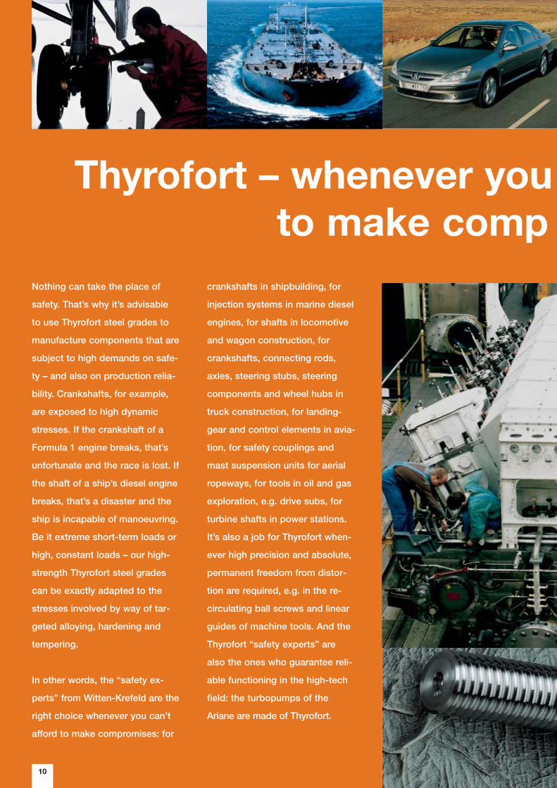
Nothing can take the place of
safety. That’s why it’s advisable
to use Thyrofort steel grades to
manufacture components that are
subject to high demands on safe-
ty – and also on production relia-
bility. Crankshafts, for example,
are exposed to high dynamic
stresses. If the crankshaft of a
Formula 1 engine breaks, that’s
unfortunate and the race is lost. If
the shaft of a ship’s diesel engine
breaks, that’s a disaster and the
ship is incapable of manoeuvring.
Be it extreme short-term loads or
high, constant loads – our high-
strength Thyrofort steel grades
can be exactly adapted to the
stresses involved by way of tar-
geted alloying, hardening and
tempering.
In other words, the “safety ex-
perts” from Witten-Krefeld are the
right choice whenever you can’t
afford to make compromises: for
10
Thyrofort – whenever you to make comp
crankshafts in shipbuilding, for
injection systems in marine diesel
engines, for shafts in locomotive
and wagon construction, for
crankshafts, connecting rods,
axles, steering stubs, steering
components and wheel hubs in
truck construction, for landing-
gear and control elements in avia-
tion, for safety couplings and
mast suspension units for aerial
ropeways, for tools in oil and gas
exploration, e.g. drive subs, for
turbine shafts in power stations.
It’s also a job for Thyrofort when-
ever high precision and absolute,
permanent freedom from distor-
tion are required, e.g. in the re-
circulating ball screws and linear
guides of machine tools. And the
Thyrofort “safety experts” are
also the ones who guarantee reli-
able functioning in the high-tech
field: the turbopumps of the
Ariane are made of Thyrofort.
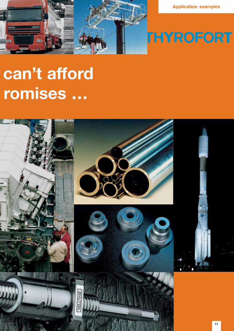
11
can’t affordromises …
THYROFORT
Application examples

12
THYROFORT
Thyrofort is also the right choice
when things get rough and tough
in the building industry, too. On
the one hand, the chisels of demo-
lition hammers, or the teeth of
excavators and rippers, need to
have the right strength in order not
to break. On the other hand, they
need to be given long-term wear
resistance by way of appropriate
hardening.
The high resistance to pressure
also makes Thyrofort steel grades
ideally safe materials, e.g. for the
manufacture of steel cylinders for
industrial gases and oxygen, as
well as for pipeline construction.

13
Thyrofort –
the “safety experts”
from Witten and Krefeld
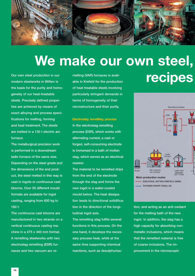
14
We make our own steel, recipes Our own steel production in our
modern steelworks in Witten is
the basis for the purity and homo-
geneity of our heat-treatable
steels. Precisely defined proper-
ties are achieved by means of
exact alloying and process speci-
fications for melting, forming
and heat treatment. The steels
are melted in a 130 t electric arc
furnace.
The metallurgical precision work
is performed in a downstream
ladle furnace of the same size.
Depending on the steel grade and
the dimensions of the end prod-
uct, the steel melted in this way is
cast in ingots or continuous cast
blooms. Over 50 different mould
formats are available for ingot
casting, ranging from 600 kg to
160 t.
The continuous cast blooms are
manufactured in two strands on a
vertical continuous casting ma-
chine in a 475 x 340 mm format.
A remelting steelworks with two
electroslag remelting (ESR) fur-
naces and two vacuum arc re-
tion, and acting as an anti-oxidant
for the melting bath of the new
ingot. In addition, the slag has a
high capacity for absorbing non-
metallic inclusions, which means
that the remelted material is free
of coarse inclusions. The im-
provement in the microscopic
melting (VAR) furnaces is avail-
able in Krefeld for the production
of heat treatable steels involving
particularly stringent demands in
terms of homogeneity of their
microstructure and their purity.
Electroslag remelting process
In the electroslag remelting
process (ESR), which works with
alternating current, a cast or
forged, self-consuming electrode
is immersed in a bath of molten
slag, which serves as an electrical
resistor.
The material to be remelted drips
from the end of the electrode
through the slag and forms the
new ingot in a water-cooled
mould below. The heat dissipa-
tion leads to directional solidifica-
tion in the direction of the longi-
tudinal ingot axis.
The remelting slag fulfils several
functions in this process. On the
one hand, it develops the neces-
sary process heat, while at the
same time supporting chemical
reactions, such as desulphurisa-
EDELSTAHL WITTEN-KREFELD GMBH
THYSSEN KRUPP STAHL AG
Remelting facilities
Scrap
Ladlefurnace
130 t electricarc furnace
Main production routes
Ladle tankdegasser
(VD / VOD)
ESR
VAR
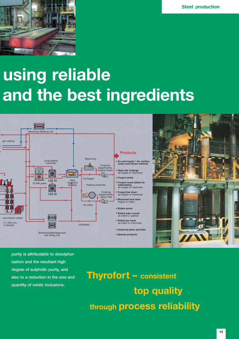
15
using reliableand the best ingredients
purity is attributable to desulphur-
isation and the resultant high
degree of sulphidic purity, and
also to a reduction in the size and
quantity of oxidic inclusions.
Thyrofort – consistent
top quality
through process reliability
LSX 25
LSX 55
Products
• As-cast ingots / As-continu-ously-cast bloom material
• Open-die forgingsas-forged or machined
• Forged semis
• Forged round billets for tubemakingas-forged or machined
• Forged bar steelas-forged or machined
• Machined tool steelforged or rolled
• Rolled semis
• Rolled tube roundsas-rolled or peeled
• Rolled bar steelas-rolled or machined
• Universal plate and flats
• Special products
got casting
uous bloom caster
5 x 340 mm,2 strands
Blooming-slabbing mill
33 MN press
Long forgingmachines
Machining
Finishingdepartments,forging shops
Finishingdepartments,rolling mills
Peeling machines
As-forged
As-rolled
Untreated
Blooming/billet/large-sizebar rolling mill
Heattreatmentfacilities
Steel production

16
Thyrofort – madeyour “extended workbench”Vacuum arc remelting process
The vacuum arc remelting (VAR)
process works with cast or
forged, self-consuming elec-
trodes in a vacuum.
Using an electric arc in a vacuum,
a melting bath is generated in a
copper crucible, which acts as
the opposite pole to the remelting
electrode and is connected to a
DC voltage source via current
contacts.
A new ingot is formed from the
liquefied electrode material drop
by drop in a continuous process.
In the VAR process, refinement of
the steel is brought about by the
reaction of the oxygen dissolved
in the steel with the carbon in the
molten material under the effect
of the vacuum. This results in the
best possible degree of micro-
scopic oxidic purity and freedom
from macroscopic inclusions. As
no desulphurisation takes place
during this remelting process, the
lowest possible sulphur content
has to be set prior to remelting, in
order also to meet the most strin-
gent demands on the degree of
sulphidic purity. Moreover, this
process guarantees the lowest
possible quantities of dissolved
gases in the steel and a homo-
geneous microstructure free of
segregation.
Hot forming and finishing
The blooming mill in Witten pro-
duces semi-finished products,
steel bars and universal plate/flat
dimensions. Two modern finishing
lines for checking the inner and
outer surface condition, as well
as the dimensions and identity,
are available for rolled and forged
products and steel bars. The
forge is equipped with a 33 MN
press, a GFM LSX 55 horizontal
long forging machine and a GFM
LSX 25 long forging machine.

17
-to-measure work from
parts. We put extensive consult-
ing know-how and modern ma-
chining facilities at the disposal
of our customers.
After straightening, rolled or
forged bar steel and round billets
up to 300 mm diameter for tube-
making can be peeled, pressure
polished and chamfered in
Krefeld and Witten. Rotationally
symmetrical parts with a piece
weight of up to 20 tonnes are
manufactured in Krefeld on con-
ventional and modern CNC lathes
and grinding machines. The key
production fields are shafts, cylin-
ders and rolls for continuous
casting.
Machining
Edelstahl Witten-Krefeld offers
not only an optimum material in
various forms, but also pre-
machined and ready-to-install
Our facilities
pay off for you
Steel processing
Depending on the type and quan-
tity of the alloying element added,
certain specific properties can be
attained. Chromium improves
hardenability and through-
hardening by reducing the critical
cooling rate needed for the
formation of martensite. Nickel
also improves through-hardening
and, at the same time, increases
the absorbed energy per cross-
sectional area at low tempera-
tures. Molybdenum is used in
conjunction with other alloying
elements to increase the 0.2 %
proof stress and tensile strength
while decreasing the tendency to
tempering brittleness.
A vanadium content of approx.
0.10% improves tempering resis-
tance and reduces sensitivity to
overheating during hardening.
Boron-alloyed steels
The development of cheaper
steels by saving on expensive
alloying elements has led to
increasing use of heat-treatable
boron-alloyed steels. The use of
these steels for fastening ele-
ments is already state-of-the-art
today.
Boron-alloyed steels are already
being used as standard materials
for special solid, heat-treated
parts, like excavator teeth, axle
parts, rotors, etc. Efforts are
being made nationally and inter-
nationally to standardize these
heat-treatable steels for general
application. These steels can be
supplied on request, provided
that certain minimum order quan-
tities are observed.
Table 1 shows an overview of the
grades of heat-treatable steels
dealt with in this catalogue, while
Tables 2 and 3 provide an over-
view of the chemical composi-
tions.
Unalloyed steels
Apart from carbon, unalloyed
steels contain manganese as the
main alloying element.
The steels listed in Tables 1 and 2
are given in the order of increas-
ing carbon content and comply
with European Standard DIN EN
10083, Part 1 – “Heat-Treatable
Steels” (1996 edition) or DIN
17212 – “Steels for Flame and
Induction Hardening” (August
1972 edition).
Alloyed steels
Apart from carbon and manga-
nese, alloyed steels contain other
alloying elements. The most
important of these are chromium,
nickel, molybdenum and vana-
dium.
The steels given in Tables 1 and
3, in the order of their alloy com-
position, Cr, Cr–V, Cr–Mo,
Cr–Mo–V, Cr–Ni–Mo, Ni-Cr-Mo,
correspond to European Standard
DIN EN 10083, Part 1, or DIN
17201 - “Forgings and Forged
Bars of Heat-Treatable Steels”.
18
Overview of grades andchemical compositions

Page 24 – 25 Thyrofort C 22 E 1.1151 C22E DIN EN 10083 / DIN E 17201
Page 26 – 27 Thyrofort C 35 E 1.1181 C35E DIN EN 10083 / DIN E 17201
Thyrofort C 35 R 1.1180 C35R DIN EN 10083
Thyrofort Cf 35 1.1183 – DIN 17212
Page 28 – 29 Thyrofort C 45 E 1.1191 C45E DIN EN 10083 / DIN E 17201
Thyrofort C 45 R 1.1201 C45R DIN EN 10083
Thyrofort Cf 45 1.1193 – DIN 17212
Page 30 – 31 Thyrofort Cf 53 1.1213 – DIN 17212
Page 32 – 33 Thyrofort C 55 E 1.1203 C55E DIN EN 10083 / DIN E 17201
Thyrofort C 55 R 1.1209 C55R DIN EN 10083 / DIN E 17201
Page 34 – 35 Thyrofort C 60 E 1.1221 C60E DIN EN 10083 / DIN E 17201
Thyrofort C 60 R 1.1223 C60R DIN EN 10083
Page 36 – 37 Thyrofort 28 Mn 6 1.1170 28Mn6 DIN EN 10083 / DIN E 17201
Page 38 – 39 Thyrofort 46 Cr 2 1.7006 46Cr2 DIN EN 10083
Thyrofort 46 CrS 2 1.7025 46CrS2 DIN EN 10083
Page 40 – 41 Thyrofort 34 Cr 4 1.7033 34Cr4 DIN EN 10083
Thyrofort 34 CrS 4 1.7037 34CrS4 DIN EN 10083
Page 42 – 43 Thyrofort 37 Cr 4 1.7034 37Cr4 DIN EN 10083
Thyrofort 37 CrS 4 1.7038 37CrS4 DIN EN 10083
Page 44 – 45 Thyrofort 41 Cr 4 1.7035 41Cr4 DIN EN 10083
Thyrofort 41 CrS 4 1.7039 41CrS4 DIN EN 10083
Page 46 – 47 Thyrofort 51 CrV 4 1.8159 51CrV4 DIN EN 10083
Page 48 – 49 Thyrofort 25 CrMo 4 1.7218 25CrMo4 DIN EN 10083 / DIN E 17201
Thyrofort 25 CrMoS 4 1.7213 25CrMoS4 DIN EN 10083
Page 50 – 51 Thyrofort 34 CrMo 4 1.7220 34CrMo4 DIN EN 10083 / DIN E 17201
Thyrofort 34 CrMoS 4 1.7226 34CrMoS4 DIN EN 10083
Page 52 – 53 Thyrofort 42 CrMo 4 1.7225 42CrMo4 DIN EN 10083 / DIN E 17201
Thyrofort 42 CrMoS 4 1.7227 42CrMoS4 DIN EN 10083
Page 54 – 55 Thyrofort 50 CrMo 4 1.7228 50CrMo4 DIN EN 10083 / DIN E 17201
Page 56 – 57 Thyrofort 30 CrMoV 9 1.7707 – DIN E 17201
Page 58 – 59 Thyrofort 36 CrNiMo 4 1.6511 36CrNiMo4 DIN EN 10083
Page 60 – 61 Thyrofort 34 CrNiMo 6 1.6582 34CrNiMo6 DIN EN 10083 / DIN E 17201
Page 62 – 63 Thyrofort 30 CrNiMo 8 1.6580 30CrNiMo8 DIN EN 10083 / DIN E 17201
Page 64 – 65 Thyrofort 36 NiCrMo 16 1.6773 36NiCrMo16 DIN EN 10083
Unallo
yed steels
Allo
yed steels
Grades Material No. Code name acc. Standardized into EN 10083
Overview of grades, Table 1
19
Technical information

Thyrofort C 22 E
Thyrofort C 35 E
Thyrofort C 35 R
Thyrofort Cf 351
Thyrofort C 45 E
Thyrofort C 45 R
Thyrofort Cf 451
Thyrofort Cf 531
Thyrofort C 55 E
Thyrofort C 55 R
Thyrofort C 60 E
Thyrofort C 60 R
Thyrofort 28 Mn 6
Thyrofort 46 Cr 2
Thyrofort 46 CrS 2
Thyrofort 34 Cr 4
Thyrofort 34 CrS 4
Thyrofort 37 Cr 4
Thyrofort 37 CrS 4
Thyrofort 41 Cr 4
Thyrofort 41 CrS 4
Thyrofort 51 CrV 4
Thyrofort 25 CrMo 4
Thyrofort 25 CrMoS 4
Thyrofort 34 CrMo 4
Thyrofort 34 CrMoS 4
Thyrofort 42 CrMo 4
Thyrofort 42 CrMoS 4
Thyrofort 50 CrMo 4
Thyrofort 30 CrMoV 91
Thyrofort 36 CrNiMo 4
Thyrofort 34 CrNiMo 6
Thyrofort 30 CrNiMo 8
Thyrofort 36 CrNiMo16
Table 3: Alloyed steels - Steel grades and chemical composition (ladle analysis) 1To DIN E 17201
Steel grade Chemical composition to DIN EN 10083, except1 (% by weight)
Code DIN EN Mate- C Si Mn P max. S Cr Mo Ni V
name 10083 rial no.
46Cr2
46CrS2
34Cr4
34CrS4
37Cr4
37CrS4
41Cr4
41CrS4
51CrV4
25CrMo4
25CrMoS4
34CrMo4
34CrMoS4
42CrMo4
42CrMoS4
50CrMo4
36CrNiMo4
34CrNiMo6
30CrNiMo8
36CrNiMo16
1.7006
1.7025
1.7033
1.7037
1.7034
1.7038
1.7035
1.7039
1.8159
1.7218
1.7213
1.7220
1.7226
1.7225
1.7227
1.7228
1.7707
1.6511
1.6582
1.6580
1.6773
0.40
0.40
0.40
0.40
0.40
0.40
0.40
0.40
0.40
0.40
0.40
0.40
0.40
0.40
0.50–0.80
0.60–0.90
0.60–0.90
0.60–0.90
0.70–1.10
0.60–0.90
0.60–0.90
0.60–0.90
0.50–0.80
0.40–0.70
0.50–0.80
0.50–0.80
0.30–0.60
0.30–0.60
max. 0.035
0.020–0.040
max. 0.035
0.020–0.040
max. 0.035
0.020–0.040
max. 0.035
0.020–0.040
max. 0.035
max. 0.035
0.020–0.040
max. 0.035
0.020–0.040
max. 0.035
0.020–0.040
max. 0.035
0.035
max. 0.035
max. 0.035
max. 0.035
max. 0.025
0.035
0.035
0.035
0.035
0.035
0.035
0.035
0.035
0.035
0.035
0.035
0.035
0.035
0.030
0.40–0.60
0.90–1.20
0.90–1.20
0.90–1.20
0.90–1.20
0.90–1.20
0.90–1.20
0.90–1.20
0.90–1.20
2.30–2.70
0.90–1.20
1.30–1.70
1.80–2.20
1.60–2.00
–
–
–
–
–
0.15–0.30
0.15–0.30
0.15–0.30
0.15–0.30
0.15–0.25
0.15–0.30
0.15–0.30
0.30–0.50
0.25–0.45
–
–
–
–
–
–
–
–
–
0.10–0.20
–
–
–
–
0.42–0.50
0.30–0.37
0.34–0.41
0.38–0.45
0.47–0.55
0.22–0.29
0.30–0.37
0.38–0.45
0.46–0.54
0.26–0.34
0.32–0.40
0.30–0.38
0.26–0.34
0.32–0.39
–
–
–
–
–
–
–
–
–
< 0.60
0.90–1.20
1.30–1.70
1.80–2.20
3.60–4.10
20
Table 2: Unalloyed steels - Steel grades and chemical composition (ladle analysis) 1To DIN 17212
Steel grade Chemical composition to DIN EN 10083, except1 (% by weight)
Code DIN EN Mate- C Si Mn P max. S Cr Mo Ni Cr+Mo+
name 10083 rial No. Ni max.
C22E
C35E
C35R
C45E
C45R
C55E
C55R
C60E
C60R
28Mn6
1.1151
1.1181
1.1180
1.1183
1.1191
1.1201
1.1193
1.1213
1.1203
1.1209
1.1221
1.1223
1.1170
max. 0.40
max. 0.40
0.15–0.35
max. 0.40
0.15–0.35
0.15–0.35
0.40
0.40
0.40
0.40–0.70
0.50–0.80
0.50–0.80
0.50–0.80
0.50–0.80
0.40–0.70
0.60–0.90
0.60–0.90
1.30–1.65
max. 0.035
max. 0.035
0.020–0.040
max. 0.035
max. 0.035
0.020–0.040
max. 0.035
max. 0.035
max. 0.035
0.020–0.040
max. 0.035
0.020–0.040
max. 0.035
0.035
0.035
0.025
0.035
0.025
0.025
0.035
0.035
0.035
max. 0.40
max. 0.40
–
max. 0.40
–
–
max. 0.40
max. 0.40
max. 0.40
max. 0.10
max. 0.10
–
max. 0.10
–
–
max. 0.10
max. 0.10
max. 0.10
0.63
0.63
–
0.63
–
–
0.63
0.63
0.63
0.17–0.24
0.32–0.39
0.33–0.39
0.42–0.50
0.43–0.49
0.50–0.57
0.52–0.60
0.57–0.65
0.25–0.32
max. 0.40
max. 0.40
–
max. 0.40
–
–
max. 0.40
max. 0.40
max. 0.40
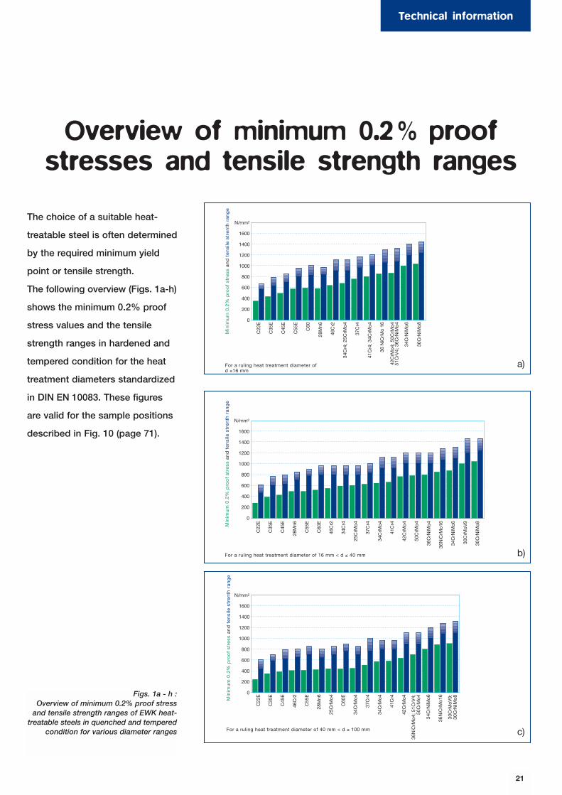
N/mm2
1600
1400
1200
1000
800
600
400
200
0
C22
E
C35
E
C45
E
C55
E
C60
28M
n6
46C
r2
34C
r4; 2
5CrM
o4
37C
r4
41C
r4; 3
4CrM
o4
36 N
iCrM
o 16
42C
rMo4
; 50C
rMo4
51C
rV4;
36C
rNiM
o4
34C
rNiM
o6
30C
rNiM
o8
Min
imu
m 0
.2%
pro
of
stre
ss a
nd
ten
sile
str
enth
ran
ge
For a ruling heat treatment diameter ofd ≤16 mm
Min
imu
m 0
.2%
pro
of
stre
ss a
nd
ten
sile
str
enth
ran
ge
N/mm2
1600
1400
1200
1000
800
600
400
200
0
C22
E
C35
E
C45
E
28M
n6
C55
E
C60
E
46C
r2
34C
r4
25C
rMo4
37C
r4
34C
rMo4
41C
r4
42C
rMo4
50C
rMo4
36C
rNiM
o4
36N
iCrM
o16
34C
rNiM
o6
30C
rMoV
9
30C
rNiM
o8
For a ruling heat treatment diameter of 16 mm < d ≤ 40 mm
N/mm2
1600
1400
1200
1000
800
600
400
200
0
C22
E
C35
E
C45
E
46C
r2
C55
E
28M
n6
25C
rMo4
C60
E
34C
rMo4
37C
r4
34C
rMo4
41C
r4
42C
rMo4
34C
rNiM
o6
36N
iCrM
o16
For a ruling heat treatment diameter of 40 mm < d ≤ 100 mm
Min
imu
m 0
.2%
pro
of
stre
ss a
nd
ten
sile
str
enth
ran
ge
36N
iCrM
o4; 5
1CrV
4;50
CrM
o4
30C
rMoV
9; 3
0CrN
iMo8
The choice of a suitable heat-
treatable steel is often determined
by the required minimum yield
point or tensile strength.
The following overview (Figs. 1a-h)
shows the minimum 0.2% proof
stress values and the tensile
strength ranges in hardened and
tempered condition for the heat
treatment diameters standardized
in DIN EN 10083. These figures
are valid for the sample positions
described in Fig. 10 (page 71).
Overview of minimum 0.2% proof stresses and tensile strength ranges
Figs. 1a - h :Overview of minimum 0.2% proof stress
and tensile strength ranges of EWK heat-treatable steels in quenched and tempered
condition for various diameter ranges
21
Technical information
a)
b)
c)

For a ruling heat treatment diameter of 100 mm < d ≤ 160 mm
Min
imu
m 0
.2%
pro
of
stre
ss a
nd
ten
sile
str
enth
ran
ge
N/mm2
1600
1400
1200
1000
800
600
400
200
0
C22
E
C35
E
C45
E
28M
n6
C55
E
C60
E
25C
rMo4
34C
rMo4
42C
rMo4
36C
rNiM
o4
50C
rMo4
; 51C
rV4
34C
rNiM
o6
30C
rMoV
9; 3
6NiC
rMo1
6;30
CrN
iMo8
51C
rV4;
34C
rNiM
o6
30C
rMoV
9;30
CrN
iMo8
Min
imu
m 0
.2%
pro
of
stre
ss a
nd
ten
sile
str
enth
ran
ge
N/mm2
1600
1400
1200
1000
800
600
400
200
0
C22
E
C35
E
C45
E
C55
E
28M
n6
C60
E
25C
rMo4
34C
rMo4
42C
rMo4
36C
rNiM
o4
50C
rMo4
36N
iCrM
o16
For a ruling heat treatment diameterof 160 mm < d ≤ 250 mm
Min
imu
m 0
.2%
pro
of
stre
ss a
nd
ten
sile
str
enth
ran
ge
N/mm2
1600
1400
1200
1000
800
600
400
200
0
C22
E
C35
E
C45
E
C55
E
28M
n6
C60
E
25C
rMo4
34C
rMo4
42C
rMo4
30C
rMoV
9
30C
rNiM
o8
For a ruling heat treatment diameter of250 mm < d ≤ 500 mm
34C
rNiM
o6;
50C
rMo4
Min
imu
m 0
.2%
pro
of
stre
ss a
nd
ten
sile
str
enth N/mm2
1600
1400
1200
1000
800
600
400
200
0
42C
rMo4
50C
rMo4
34C
rNiM
o6
30C
rNiM
o8
For a ruling heat treatment diameter of500 mm < d ≤ 750 mm
Min
imu
m 0
.2%
pro
of
stre
ss a
nd
ten
sile
str
enth
N/mm2
1600
1400
1200
1000
800
600
400
200
0
34C
rNiM
o6
30C
rNiM
o8
For a ruling heat treatment diameter of750 mm < d ≤ 1000 mm
22
Mindeststreckgrenze
Zugfestigkeitsbereich
d)
e)
f)
g)
h)
Minimum 0.2% proof stress
Tensile strength range

23
Edelstahl Witten-Krefeld –heat-treatable steel, the
way you need it.Wherever you may be.
THYROFORTTHYROFORT
THYROFORT
THYROFORTTHYROFORT
THYROFORT
Edelstahl Witten-Krefeld –heat-treatable steel, the
way you need it.Wherever you may be.

C
0.17 � 0.24
Si
≤0.40
Mn
0.40 � 0.70
P
≤0.035
S
≤0.035
Cr
≤0.40
Mo
≤0.10
Ni
≤0.40
Cr+Mo+Ni
≤0.63
Normalising
880 � 920
Hardening
860 � 900
Quenching medium
Water
Tempering
550 � 660
THYROFORT® C 22 E
Material No.
1.1151
Code
C22E
Material No.Code
Chemicalcomposition
Typical analysis in %
Mechanical properties in differenttreatment conditions
Heat treatment
Quenched and tempered Q + TNormalised N
Heat treatmentdiameter
in mmØ
0.2% proofstress
(Rp 0.2) min.N/mm2
Tensile strengthin N/mm2
Rmmin.
Elongation atfracture in %
Amin.
0.2% proofstress
(Rp 0.2) min.N/mm2
Tensile strengthin N/mm2
Rmmin.
Elongation atfracture in %
Amin.
Reduction ofarea at fracture
in % Zmin.
Notch impactenergy (ISO-V)
in J KVmin.
≤ 16> 16 ≤ 40> 40 ≤ 100
> 40 ≤ 100>100 ≤ 160>160 ≤ 250>250 ≤ 500>500 ≤1000
240210210
�230220210200
430410410
�410 � 530410 � 530410 � 530410 � 530
242525
�27262524
340290�
260220220210�
500 � 650470 � 620
�
450 � 600410 � 540410 � 540410 � 540
�
2022�
24262625�
5050�
�����
5050�
45404035�
To DIN E 17201
Temperatures in °C
24
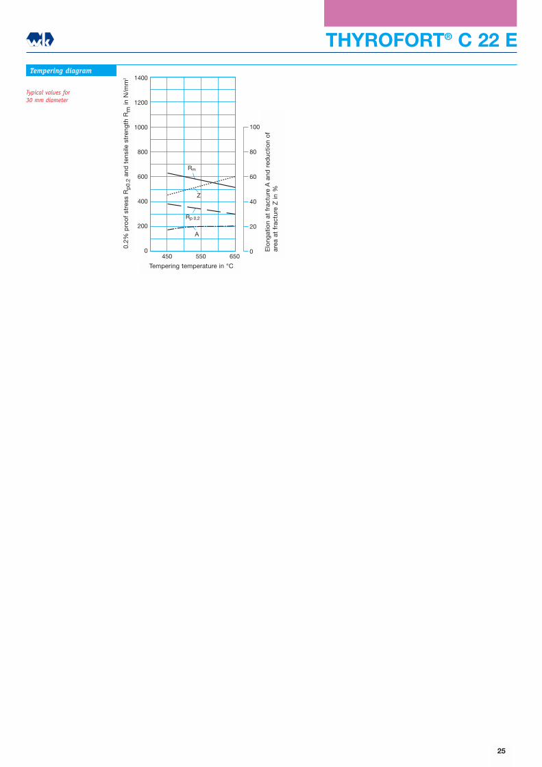
THYROFORT® C 22 ETempering diagram
Typical values for 30 mm diameter
1400
1200
1000
800
600
400
200
0450 550 650
100
80
60
40
20
0
Z
Rm
Rp 0,2
A
Anlasstemperatur oCB
ruch
deh
nung
A u
nd B
ruch
eins
chnü
rung
Z in
%
Str
eckg
renz
e R
p 0
,2 u
nd Z
ugfe
stig
keit
Rm
in N
/mm
2
25
Elo
ngat
ion
at f
ract
ure
A a
nd r
educ
tion
of
area
at
frac
ture
Z in
%
0.2%
pro
of
stre
ss R
p0.
2an
d t
ensi
le s
tren
gth
Rm
in N
/mm
2
Tempering temperature in °C
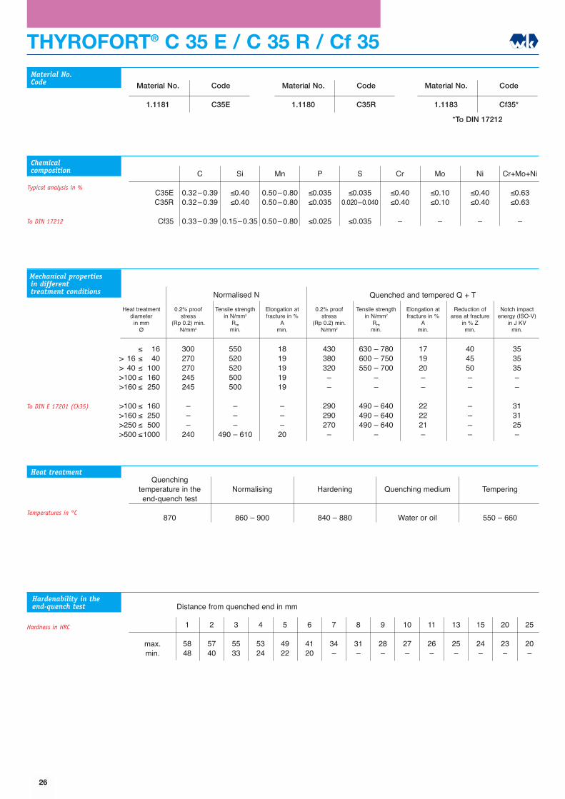
THYROFORT® C 35 E / C 35 R / Cf 35
1
5848
2
5740
3
5533
4
5324
5
4922
6
4120
7
34�
8
31�
9
28�
10
27�
11
26�
13
25�
15
24�
20
23�
25
20�
Quenching temperature in theend-quench test
870
Normalising
860 � 900
Hardening
840 � 880
Quenching medium
Water or oil
Tempering
550 � 660
Material No.
1.1181
Code
C35E
Material No.
1.1180
Code
C35R
Material No.
1.1183
Code
Cf35*
C
0.32�0.390.32�0.39
0.33�0.39
Si
≤0.40≤0.40
0.15�0.35
Mn
0.50�0.800.50�0.80
0.50�0.80
P
≤0.035≤0.035
≤0.025
S
≤0.0350.020�0.040
≤0.035
Cr
≤0.40≤0.40
�
Mo
≤0.10≤0.10
�
Ni
≤0.40≤0.40
�
Cr+Mo+Ni
≤0.63≤0.63
�
C35E C35R
Cf35
Material No.Code
Chemicalcomposition
Heat treatment
Typical analysis in %
max.min.
Mechanical properties in differenttreatment conditions Quenched and tempered Q + TNormalised N
Heat treatmentdiameter
in mmØ
0.2% proofstress
(Rp 0.2) min.N/mm2
Tensile strengthin N/mm2
Rmmin.
Elongation atfracture in %
Amin.
0.2% proofstress
(Rp 0.2) min.N/mm2
Tensile strengthin N/mm2
Rmmin.
Elongation atfracture in %
Amin.
Reduction ofarea at fracture
in % Zmin.
Notch impactenergy (ISO-V)
in J KVmin.
≤ 16> 16 ≤ 40> 40 ≤ 100>100 ≤ 160>160 ≤ 250
>100 ≤ 160>160 ≤ 250>250 ≤ 500>500 ≤1000
300270270245245
���
240
550520520500500
���
490 � 610
1819191919
���20
430380320��
290290270�
630 � 780600 � 750550 � 700
��
490 � 640490 � 640490 � 640
�
171920��
222221�
404550��
����
353535��
313125�
To DIN E 17201 (Ck35)
Hardenability in theend-quench test
Hardness in HRC
*To DIN 17212
Distance from quenched end in mm
Temperatures in °C
To DIN 17212
26

1200
1100
1000
900
800
700
600
500
400
300
200
100
0
100 101 102
100 101 102 103 104
100 101 102 103 104 105 106
AC3
AC1
A
MS
M
HV 10
B
PF
3030
20
40 45
505055
4555
454060
406070
3060
15
6085
3 35
322
294
267
294 253
236
236
236205
201
196
Tem
per
atur
in o
C
Zeit in s
Zeit in min
Zeit in h
Härtewerte
THYROFORT® C 35 E / C 35 R / Cf 35
1400
1200
1000
800
600
400
200
0450 550 650
Z
Rp 0,2
Rm
A
100
80
60
40
20
0
Anlasstemperatur oC
Str
eckg
renz
e R
p 0
,2 u
nd Z
ugfe
stig
keit
Rm
in N
/mm
2
Bru
chd
ehnu
ng A
und
Bru
chei
nsch
nüru
ng Z
in %
Tempering diagram
Typical values for60 mm diameter
Hardenability diagram
Time-temperature-transformation diagramfor continuous cooling
70
65
60
55
50
45
40
35
30
25
200 5 10 15 20 25 30 35 40 45 50 55
Abstand von der abgeschreckten Stirnfläche in mm
Här
te in
HR
C
27
Elo
ngat
ion
at f
ract
ure
A a
nd r
educ
tion
of
area
at
frac
ture
Z in
%
0.2%
pro
of
stre
ss R
p0.
2an
d t
ensi
le s
tren
gth
Rm
in N
/mm
2
Tempering temperature in °C
Har
dne
ss in
HR
C
Distance from quenched end in mm
Time in s
Time in min.
Time in h
Tem
per
atur
e in
°C
Hardness
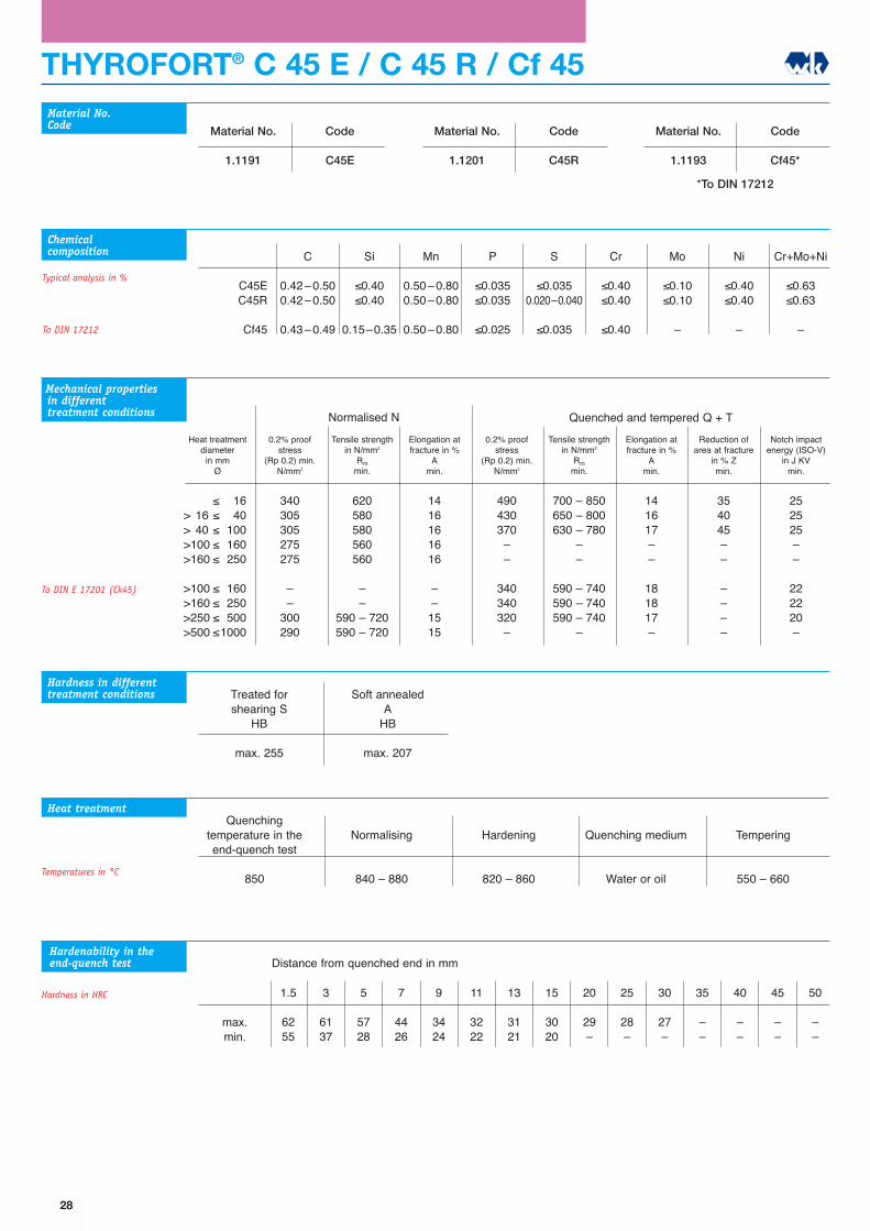
THYROFORT® C 45 E / C 45 R / Cf 45
1.5
6255
3
6137
5
5728
7
4426
9
3424
11
3222
13
3121
15
3020
20
29�
25
28�
30
27�
35
��
40
��
45
��
50
��
Quenching temperature in theend-quench test
850
Normalising
840 � 880
Hardening
820 � 860
Quenching medium
Water or oil
Tempering
550 � 660
Material No.
1.1191
Code
C45E
Material No.
1.1201
Code
C45R
Material No.
1.1193
Code
Cf45*
C
0.42�0.500.42�0.50
0.43�0.49
Si
≤0.40≤0.40
0.15�0.35
Mn
0.50�0.800.50�0.80
0.50�0.80
P
≤0.035≤0.035
≤0.025
S
≤0.0350.020�0.040
≤0.035
Cr
≤0.40≤0.40
≤0.40
Mo
≤0.10≤0.10
�
Ni
≤0.40≤0.40
�
Cr+Mo+Ni
≤0.63≤0.63
�
C45EC45R
Cf45
Material No.Code
Chemicalcomposition
Heat treatment
Typical analysis in %
max.min.
Mechanical properties in differenttreatment conditions Quenched and tempered Q + TNormalised N
Heat treatmentdiameter
in mmØ
0.2% proofstress
(Rp 0.2) min.N/mm2
Tensile strengthin N/mm2
Rmmin.
Elongation atfracture in %
Amin.
0.2% proofstress
(Rp 0.2) min.N/mm2
Tensile strengthin N/mm2
Rmmin.
Elongation atfracture in %
Amin.
Reduction ofarea at fracture
in % Zmin.
Notch impactenergy (ISO-V)
in J KVmin.
≤ 16> 16 ≤ 40> 40 ≤ 100>100 ≤ 160>160 ≤ 250
>100 ≤ 160>160 ≤ 250>250 ≤ 500>500 ≤1000
340305305275275
��
300290
620580580560560
��
590 � 720590 � 720
1416161616
��1515
490430370��
340340320�
700 � 850650 � 800630 � 780
��
590 � 740590 � 740590 � 740
�
141617��
181817�
354045��
����
252525��
222220�
To DIN E 17201 (Ck45)
Hardness in differenttreatment conditions Treated for
shearing SHB
max. 255
Soft annealedA
HB
max. 207
Hardenability in theend-quench test
Hardness in HRC
Temperatures in °C
*To DIN 17212
Distance from quenched end in mm
To DIN 17212
28
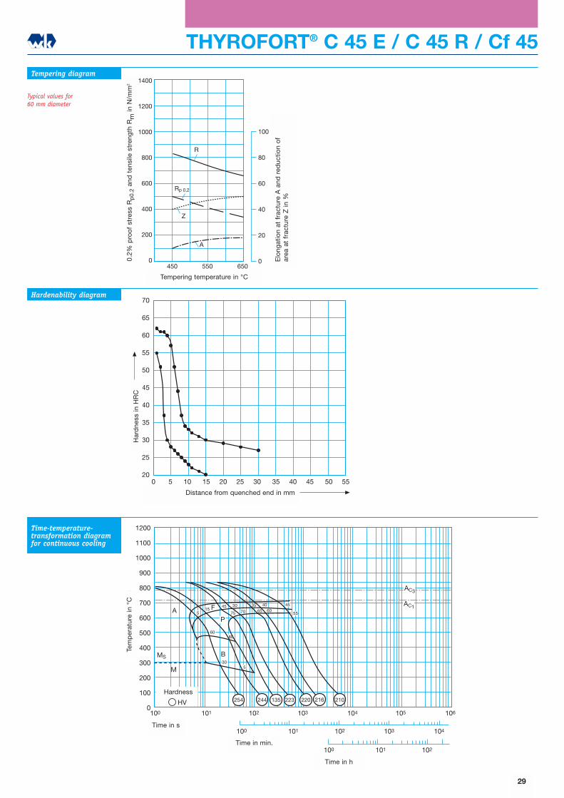
1200
1100
1000
900
800
700
600
500
400
300
200
100
0
100 101 102
100 101 102 103 104
100 101 102 103 104 105 106
AC3
AC1A
MS
M
HV
7075
60
15
B30
5
35 4065F
P55
45
80
5
45 3060
254 244 135 223 220 216 210
Tem
per
atur
in o
C
Zeit in s
Zeit in min
Zeit in h
Härtewerte
THYROFORT® C 45 E / C 45 R / Cf 45
1400
1200
1000
800
600
400
200
0450 550 650
Z
R
Rp 0,2
A
100
80
60
40
20
0
Anlasstemperatur oC
Str
eckg
renz
e R
p 0
,2 u
nd Z
ugfe
stig
keit
Rm
in N
/mm
2
Bru
chd
ehnu
ng A
und
Bru
chei
nsch
nüru
ng Z
in %
Tempering diagram
Typical values for 60 mm diameter
Hardenability diagram
Time-temperature-transformation diagramfor continuous cooling
70
65
60
55
50
45
40
35
30
25
200 5 10 15 20 25 30 35 40 45 50 55
Abstand von der abgeschreckten Stirnfläche in mm
Här
te in
HR
C
29
Elo
ngat
ion
at f
ract
ure
A a
nd r
educ
tion
of
area
at
frac
ture
Z in
%
0.2%
pro
of
stre
ss R
p0.
2an
d t
ensi
le s
tren
gth
Rm
in N
/mm
2
Tempering temperature in °C
Har
dne
ss in
HR
C
Distance from quenched end in mm
Time in s
Time in min.
Time in h
Tem
per
atur
e in
°C
Hardness

THYROFORT® Cf 53
Normalising
830 � 860
Hardening
805 � 845
Quenching medium
Water or oil
Tempering
550 � 660
Material No.
1.1213
Code
Cf53*
C
0.50�0.57
Si
0.15�0.35
Mn
0.40�0.70
P
≤0.025
S
≤0.035
Material No.Code
Chemicalcomposition
Heat treatment
Typical analysis in %
Mechanical properties in differenttreatment conditions Quenched and tempered Q + TNormalised N
Heat treatmentdiameter
in mmØ
0.2% proofstress
(Rp 0.2) min.N/mm2
Tensile strengthin N/mm2
Rmmin.
Elongation atfracture in %
Amin.
0.2% proofstress
(Rp 0.2) min.N/mm2
Tensile strengthin N/mm2
Rmmin.
Elongation atfracture in %
Amin.
Reduction ofarea at fracture
in % Zmin.
Notch impactenergy (ISO-V)
in J KVmin.
≤ 16> 16 ≤ 40> 40 ≤ 100
�340340
�610 � 760610 � 760
�1616
510430400
740 � 880690 � 830640 � 780
121415
253540
���
Temperatures in °C
*To DIN 17212
30
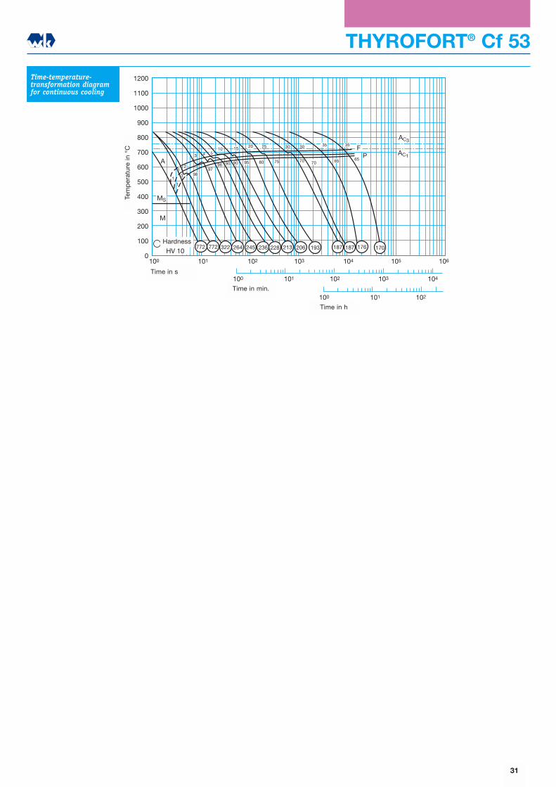
1200
1100
1000
900
800
700
600
500
400
300
200
100
0
100 101 102
100 101 102 103 104
100 101 102 103 104 105 106
AC3
AC1A
MS
M
HV 10
9897
96 95 90 95 80 75 70 70 65 65
FP
11
13
2
3 4 510 15 20 25 30 30 35 35
772 772 322 264 245 236 228 213 206 193 187 187 176 170
Tem
per
atur
in o
C
Zeit in s
Zeit in min
Zeit in h
Härtewerte
THYROFORT® Cf 53
Time-temperature-transformation diagramfor continuous cooling
31
Time in s
Time in min.
Time in h
Tem
per
atur
e in
°C
Hardness

THYROFORT® C 55 E / C 55 R
1.5
6558
3
6455
5
6033
7
5231
9
3729
11
3527
13
3426
15
3325
20
3224
25
3022
30
2920
Quenching temperature in theend-quench test
830
Normalising
825 � 865
Hardening
805 � 845
Quenching medium
Oil or water
Tempering
550 � 660
Material No.
1.1203
Code
C55E
Material No.
1.1209
Code
C55R
C
0.52�0.600.52�0.60
Si
≤0.40≤0.40
Mn
0.60�0.900.60�0.90
P
≤0.035≤0.035
S
≤0.0350.020�0.040
Cr
≤0.40≤0.40
Mo
≤0.10≤0.10
Ni
≤0.40≤0.40
Cr+Mo+Ni
≤0.63≤0.63
C55EC55R
Material No.Code
Chemicalcomposition
Heat treatment
Typical analysis in %
max.min.
Mechanical properties in differenttreatment conditions Quenched and tempered Q + TNormalised N
Heat treatmentdiameter
in mmØ
0.2% proofstress
(Rp 0.2) min.N/mm2
Tensile strengthin N/mm2
Rmmin.
Elongation atfracture in %
Amin.
0.2% proofstress
(Rp 0.2) min.N/mm2
Tensile strengthin N/mm2
Rmmin.
Elongation atfracture in %
Amin.
Reduction ofarea at fracture
in % Zmin.
Notch impactenergy (ISO-V)
in J KVmin.
≤ 16> 16 ≤ 40> 40 ≤ 100>100 ≤ 160>160 ≤ 250
>100 ≤ 160>160 ≤ 250>250 ≤ 500>500 ≤1000
370330330300300
��
320300
680640640620620
��
640 � 800640 � 800
1112121212
��1514
550490420��
390360330�
800 � 950750 � 900700 � 850
��
660 � 810630 � 780630 � 780
�
121415��
161716�
303540��
����
�����
����
To DIN E 17201 (Ck53)
Hardenability in theend-quench test
Hardness in HRC
Temperatures in °C
Distance from quenched end in mm
Hardness in differenttreatment conditions Treated for
shearing SHB
max. 255
Soft annealedA
HB
max. 229
32
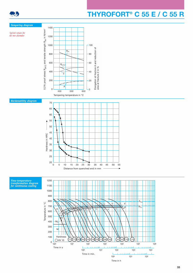
1400
1200
1000
800
600
400
200
0450 550 650
Z
A
Rm
Rp 0,2
100
80
60
40
20
0
Anlasstemperatur oC
Str
eckg
renz
e R
p 0
,2 u
nd Z
ugfe
stig
keit
Rm
in N
/mm
2
Bru
chd
ehnu
ng A
und
Bru
chei
nsch
nüru
ng Z
in %
1200
1100
1000
900
800
700
600
500
400
300
200
100
0
100 101 102
100 101 102 103 104
100 101 102 103 104 105 106
AC3
AC1A
MS
M
HV 10
85 80 70
98
97 96 95 9075 70 65 65P3
5 1015 20 25 30 30 35 35 F
12
4
31
1
772 772 322 264 245 236 228 213 206 193 187 187 176 170
Tem
per
atur
in o
C
Zeit in s
Zeit in min
Zeit in h
Härtewerte
THYROFORT® C 55 E / C 55 RTempering diagram
Typical values for 60 mm diameter
Hardenability diagram
Time-temperature-transformation diagramfor continuous cooling
70
65
60
55
50
45
40
35
30
25
200 5 10 15 20 25 30 35 40 45 50 55
Abstand von der abgeschreckten Stirnfläche in mm
Här
te in
HR
C
33
0.2%
pro
of
stre
ss R
p0.
2an
d t
ensi
le s
tren
gth
Rm
in N
/mm
2
Tempering temperature in °C
Har
dne
ss in
HR
C
Distance from quenched end in mm
Time in s
Time in min.
Time in h
Tem
per
atur
e in
°C
Hardness
Elo
ngat
ion
at f
ract
ure
A a
nd r
educ
tion
of
area
at
frac
ture
Z in
%
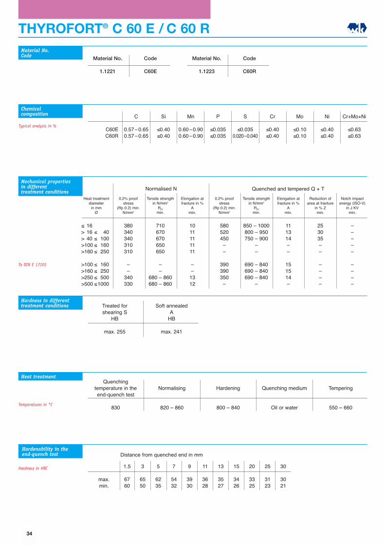
Quenching temperature in theend-quench test
830
Normalising
820 � 860
Hardening
800 � 840
Quenching medium
Oil or water
Tempering
550 � 660
Material No.
1.1221
Code
C60E
Material No.
1.1223
Code
C60R
C
0.57�0.650.57�0.65
Si
≤0.40≤0.40
Mn
0.60�0.900.60�0.90
P
≤0.035≤0.035
S
≤0.0350.020�0.040
Cr
≤0.40≤0.40
Mo
≤0.10≤0.10
Ni
≤0.40≤0.40
Cr+Mo+Ni
≤0.63≤0.63
C60EC60R
Material No.Code
Chemicalcomposition
Heat treatment
Typical analysis in %
1.5
6760
3
6550
5
6235
7
5432
9
3930
11
3628
13
3527
15
3426
20
3325
25
3123
30
3021
max.min.
THYROFORT® C 60 E / C 60 R
Mechanical properties in differenttreatment conditions
To DIN E 17201
Hardness in differenttreatment conditions Treated for
shearing SHB
max. 255
Soft annealedA
HB
max. 241
Quenched and tempered Q + TNormalised N
Heat treatmentdiameter
in mmØ
0.2% proofstress
(Rp 0.2) min.N/mm2
Tensile strengthin N/mm2
Rmmin.
Elongation atfracture in %
Amin.
0.2% proofstress
(Rp 0.2) min.N/mm2
Tensile strengthin N/mm2
Rmmin.
Elongation atfracture in %
Amin.
Reduction ofarea at fracture
in % Zmin.
Notch impactenergy (ISO-V)
in J KVmin.
≤ 16> 16 ≤ 40> 40 ≤ 100>100 ≤ 160>160 ≤ 250
>100 ≤ 160>160 ≤ 250>250 ≤ 500>500 ≤1000
380340340310310
��
340330
710670670650650
��
680 � 860680 � 860
1011111111
��1312
580520450��
390390350�
850 � 1000800 � 950750 � 900
��
690 � 840690 � 840690 � 840
�
111314��
151514�
253035��
����
�����
����
Hardenability in theend-quench test
Hardness in HRC
Temperatures in °C
Distance from quenched end in mm
34
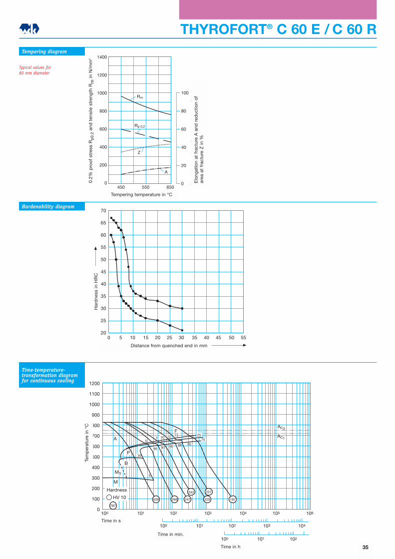
THYROFORT® C 60 E / C 60 R
1400
1200
1000
800
600
400
200
0450 550 650
Z
Rm
Rp 0,2
A
100
80
60
40
20
0
Anlasstemperatur oC
Str
eckg
renz
e R
p 0
,2 u
nd Z
ugfe
stig
keit
Rm
in N
/mm
2
Bru
chd
ehnu
ng A
und
Bru
chei
nsch
nüru
ng Z
in %
1200
1100
1000
900
800
700
600
500
400
300
200
100
0
100 101 102
100 101 102 103 104
100 101 102 103 104 105 106
A
MS
M
HV 10
B
5
P
F
20
57 10 12 15 25
95 93 90 88 8575
787
528 269 187229
227
247
242
AC3
AC1
Tem
per
atur
in o
C
Zeit in s
Zeit in min
Härtewerte
Tempering diagram
Typical values for 60 mm diameter
Hardenability diagram
Time-temperature-transformation diagramfor continuous cooling
70
65
60
55
50
45
40
35
30
25
200 5 10 15 20 25 30 35 40 45 50 55
Abstand von der abgeschreckten Stirnfläche in mm
Här
te in
HR
C
35
Elo
ngat
ion
at f
ract
ure
A a
nd r
educ
tion
of
area
at
frac
ture
Z in
%
0.2%
pro
of
stre
ss R
p0.
2an
d t
ensi
le s
tren
gth
Rm
in N
/mm
2
Tempering temperature in °C
Har
dne
ss in
HR
C
Distance from quenched end in mm
Time in s
Time in min.
Time in h
Tem
per
atur
e in
°C
Hardness
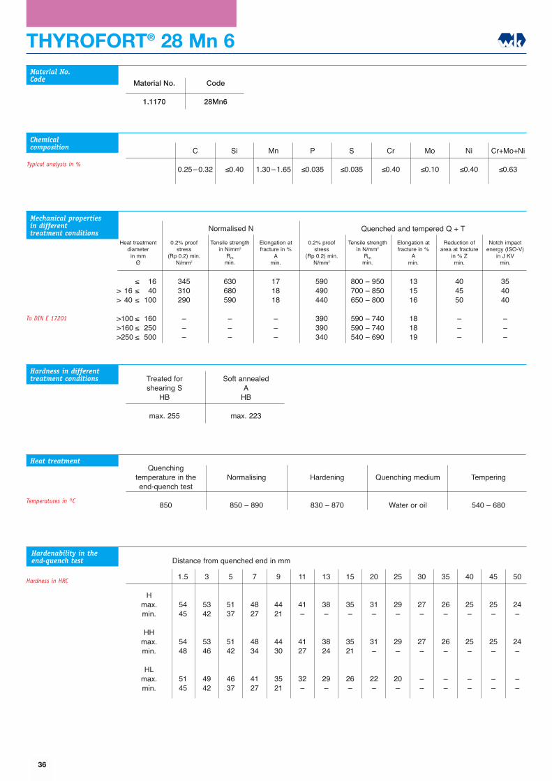
THYROFORT® 28 Mn 6
1.5
5445
5448
5145
3
5342
5346
4942
5
5137
5142
4637
7
4827
4834
4127
9
4421
4430
3521
11
41�
4127
32�
13
38�
3824
29�
15
35�
3521
26�
20
31�
31�
22�
25
29�
29�
20�
30
27�
27�
��
35
26�
26�
��
40
25�
25�
��
45
25�
25�
��
50
24�
24�
��
Quenching temperature in theend-quench test
850
Normalising
850 � 890
Hardening
830 � 870
Quenching medium
Water or oil
Tempering
540 � 680
Material No.
1.1170
Code
28Mn6
C
0.25�0.32
Si
≤0.40
Mn
1.30�1.65
P
≤0.035
S
≤0.035
Cr
≤0.40
Mo
≤0.10
Ni
≤0.40
Cr+Mo+Ni
≤0.63
Material No.Code
Chemicalcomposition
Heat treatment
Typical analysis in %
Hmax.min.
HHmax.min.
HLmax.min.
Hardenability in theend-quench test
Hardness in HRC
To DIN E 17201
Hardness in differenttreatment conditions Treated for
shearing SHB
max. 255
Soft annealedA
HB
max. 223
Temperatures in °C
Distance from quenched end in mm
36
Mechanical properties in differenttreatment conditions Quenched and tempered Q + TNormalised N
Heat treatmentdiameter
in mmØ
0.2% proofstress
(Rp 0.2) min.N/mm2
Tensile strengthin N/mm2
Rmmin.
Elongation atfracture in %
Amin.
0.2% proofstress
(Rp 0.2) min.N/mm2
Tensile strengthin N/mm2
Rmmin.
Elongation atfracture in %
Amin.
Reduction ofarea at fracture
in % Zmin.
Notch impactenergy (ISO-V)
in J KVmin.
≤ 16> 16 ≤ 40> 40 ≤ 100
>100 ≤ 160>160 ≤ 250>250 ≤ 500
345310290
���
630680590
���
171818
���
590490440
390390340
800 � 950700 � 850650 � 800
590 � 740590 � 740540 � 690
131516
181819
404550
���
354040
���
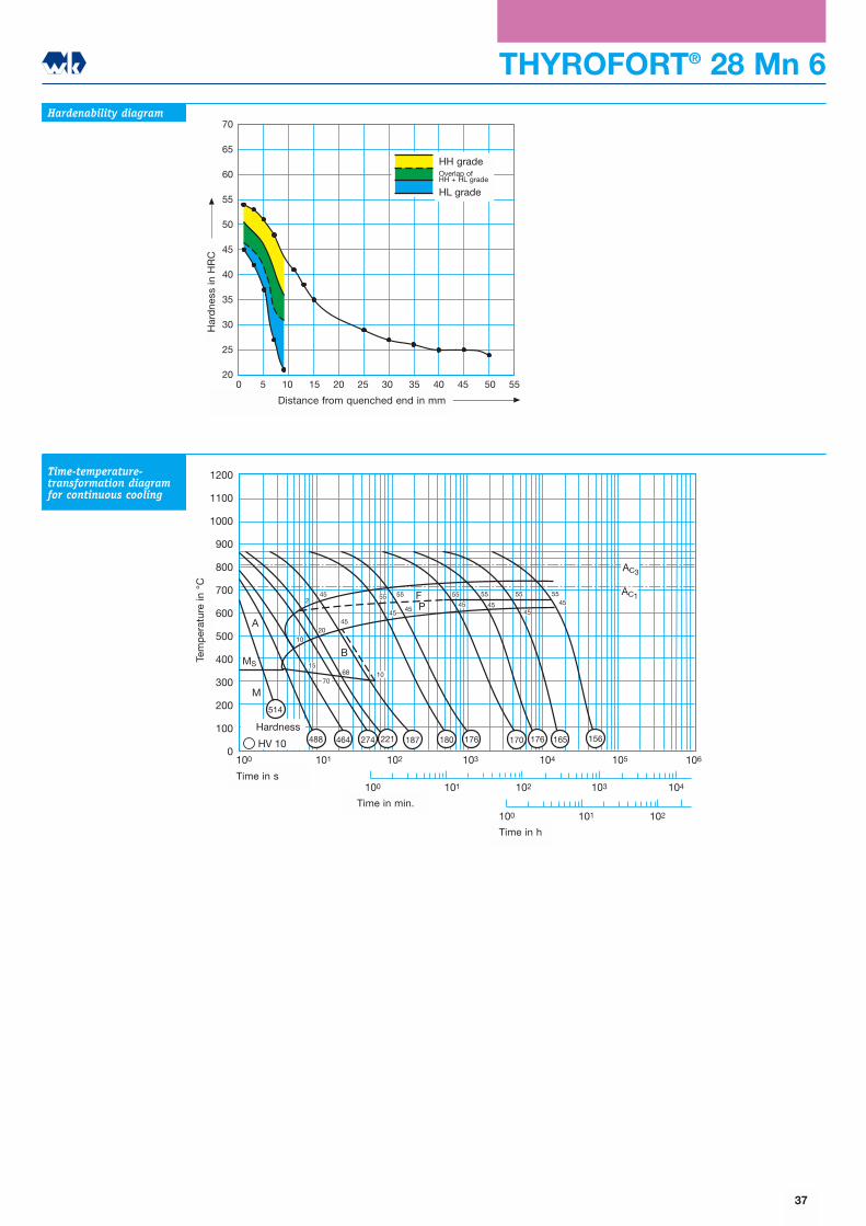
1200
1100
1000
900
800
700
600
500
400
300
200
100
0
100 101 102
100 101 102 103 104
100 101 102 103 104 105 106
AC3
AC1
A
MS
M
HV 10
1020
2
45
45
45
B
70
1568 10
55 55
45
FP
55
45 4545
4555 55 55
514
488 464 274 221 187 180 176 170 176 165 156
Tem
per
atur
in o
C
Zeit in s
Zeit in min
Zeit in h
Härtewerte
THYROFORT® 28 Mn 6Hardenability diagram
Time-temperature-transformation diagramfor continuous cooling
70
65
60
55
50
45
40
35
30
25
200 5 10 15 20 25 30 35 40 45 50 55
Abstand von der abgeschreckten Stirnfläche in mm
Här
te in
HR
C
HH-SorteÜberschneidungHH+HL-Sorte
HL-Sorte
37
Time in s
Time in min.
Time in h
Tem
per
atur
e in
°C
Hardness
Har
dne
ss in
HR
C
Distance from quenched end in mm
HH gradeOverlap ofHH + HL grade
HL grade
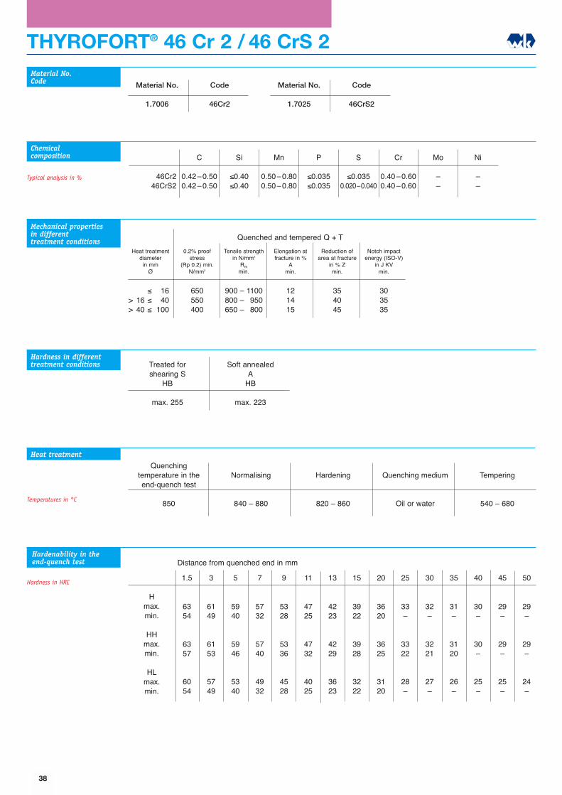
THYROFORT® 46 Cr 2 / 46 CrS 2
63 61 59 57 53 47 42 39 36 33 32 31 30 29 29
Quenching temperature in theend-quench test
850
Normalising
840 � 880
Hardening
820 � 860
Quenching medium
Oil or water
Tempering
540 � 680
Material No.
1.7006
Code
46Cr2
C
0.42�0.500.42�0.50
Si
≤0.40≤0.40
Mn
0.50�0.800.50�0.80
P
≤0.035≤0.035
S
≤0.0350.020�0.040
Cr
0.40�0.600.40�0.60
Mo
��
Ni
��
46Cr246CrS2
Mechanical properties in differenttreatment conditions
Material No.Code
Chemicalcomposition
Heat treatment
Typical analysis in %
Hmax.min.
HHmax.min.
HLmax.min.
Hardenability in theend-quench test
Hardness in HRC
Material No.
1.7025
Code
46CrS2
Heat treatmentdiameter
in mmØ
0.2% proofstress
(Rp 0.2) min.N/mm2
Tensile strengthin N/mm2
Rmmin.
Elongation atfracture in %
Amin.
Reduction ofarea at fracture
in % Zmin.
Notch impactenergy (ISO-V)
in J KVmin.
≤ 16> 16 ≤ 40> 40 ≤ 100
650550400
900 � 1100800 � 950650 � 800
121415
354045
303535
1.5 3 5 7 9 11 13 15 20 25 30 35 40 45 50
54 49 40 32 28 25 23 22 20 � � � � � �
63 61 59 57 53 47 42 39 36 33 32 31 30 29 2957 53 46 40 36 32 29 28 25 22 21 20 � � �
60 57 53 49 45 40 36 32 31 28 27 26 25 25 2454 49 40 32 28 25 23 22 20 � � � � � �
Hardness in differenttreatment conditions
Quenched and tempered Q + T
Treated forshearing S
HB
max. 255
Soft annealedA
HB
max. 223
Temperatures in °C
Distance from quenched end in mm
38

THYROFORT® 46 Cr 2 / 46 CrS 2
1200
1100
1000
900
800
700
600
500
400
300
200
100
0
100 101 102
100 101 102 103 104
100 101 102 103 104 105 106
AC3
AC1A
MS
M
HV 10
80
5
B45 7
F
P10
1065
35
6565
35
657087
53
3 15364
335
11
203530
595
592 488 393 347 303 232 221 206 183 178 176 172
Tem
per
atur
in o
C
Zeit in s
Zeit in min
Zeit in h
Härtewerte
70
65
60
55
50
45
40
35
30
25
200 5 10 15 20 25 30 35 40 45 50 55
Abstand von der abgeschreckten Stirnfläche in mm
Här
te in
HR
C
HH-SorteÜberschneidungHH+HL-Sorte
HL-Sorte
2000
1800
1600
1400
1200
1000
800
600
400
200
0
100
90
80
70
60
50
40
30
20
10
00 100 200 300 400 500 600 700
A
Z
Rp 0,2
Rm
Str
eckg
renz
e R
p 0
,2 u
nd Z
ugfe
stig
keit
Rm in
N/m
m2
Bru
chd
ehnu
ng A
und
Bru
chei
nsch
nüru
ng Z
in %
Anlasstemperatur in oC
Tempering diagram
Typical values for 60 mm diameter
Hardenability diagram
Time-temperature-transformation diagramfor continuous cooling
39
0.2%
pro
of
stre
ss R
p0.
2an
d t
ensi
le s
tren
gth
Rm
in N
/mm
2
Tempering temperature in °C
Elo
ngat
ion
at f
ract
ure
A a
nd r
educ
tion
of
area
at
frac
ture
Z in
%
Har
dne
ss in
HR
C
Distance from quenched end in mm
Time in s
Time in min.
Time in h
Tem
per
atur
e in
°C
Hardness
HH gradeOverlap ofHH + HL grade
HL grade

THYROFORT® 34 Cr 4 / 34 CrS 4
Quenching temperature in theend-quench test
850
Normalising
850 � 890
Hardening
830 � 870
Quenching medium
Water or oil
Tempering
540 � 680
Material No.
1.7033
Code
34Cr4
C
0.30�0.370.30�0.37
Si
≤0.40≤0.40
Mn
0.60�0.900.60�0.90
P
≤0.035≤0.035
S
≤0.0350.020�0.040
Cr
0.90�1.200.90�1.20
Mo
��
Ni
��
34Cr434CrS4
Material No.Code
Chemicalcomposition
Heat treatment
Typical analysis in %
Material No.
1.7037
Code
34CrS4
1.5
5749
5752
5449
3
5748
5751
5448
5
5645
5649
5245
7
5441
5445
5041
9
5235
5241
4635
11
4932
4938
4332
13
4629
4635
4029
15
4427
4433
3827
20
3923
3928
3423
25
3721
3726
3221
30
3520
3525
3020
35
34�
3424
29�
40
33�
3323
28�
45
32�
3222
27�
50
31�
3121
26�
Hmax.min.
HHmax.min.
HLmax.min.
Hardenability in theend-quench test
Hardness in HRC
Mechanical properties in differenttreatment conditions
Heat treatmentdiameter
in mmØ
0.2% proofstress
(Rp 0.2) min.N/mm2
Tensile strengthin N/mm2
Rmmin.
Elongation atfracture in %
Amin.
Reduction ofarea at fracture
in % Zmin.
Notch impactenergy (ISO-V)
in J KVmin.
≤ 16> 16 ≤ 40> 40 ≤ 100
700590460
900 � 1100800 � 950700 � 850
121415
354045
354040
Quenched and tempered Q + T
Hardness in differenttreatment conditions Treated for
shearing SHB
max. 255
Soft annealedA
HB
max. 223
Temperatures in °C
Distance from quenched end in mm
40

1200
1100
1000
900
800
700
600
500
400
300
200
100
0
100 101 102
100 101 102 103 104
100 101 102 103 104 105 106
AC1
AC3
A
M
MS
HV 10
3
35
8
9092
94
92
B
550 498 366 334 297 291294
253 219 212 206196
189
20
87
3F P
3 5 15 20 25 30 30 35
8580 75 70 70 65
Tem
per
atur
in o
C
Zeit in s
Zeit in min
Zeit in h
Härtewerte
THYROFORT® 34 Cr 4 / 34 CrS 4
2000
1800
1600
1400
1200
1000
800
600
400
200
0
100
90
80
70
60
50
40
30
20
10
00 100 200 300 400 500 600 700
Rm
Z
A
Rp 0,2S
trec
kgre
nze
Rp
0,2
und
Zug
fest
igke
it R
m in
N/m
m2
Bru
chd
ehnu
ng A
und
Bru
chei
nsch
nüru
ng Z
in %
Anlasstemperatur in oC
Tempering diagram
Typical values for 30 mm diameter
Hardenability diagram
Time-temperature-transformation diagramfor continuous cooling
70
65
60
55
50
45
40
35
30
25
200 5 10 15 20 25 30 35 40 45 50 55
Abstand von der abgeschreckten Stirnfläche in mm
Här
te in
HR
C
HH-SorteÜberschneidungHH+HL-Sorte
HL-Sorte
41
Elo
ngat
ion
at f
ract
ure
A a
nd r
educ
tion
of
area
at
frac
ture
Z in
%
0.2%
pro
of
stre
ss R
p0.
2an
d t
ensi
le s
tren
gth
Rm
in N
/mm
2
Tempering temperature in °C
Har
dne
ss in
HR
C
Distance from quenched end in mm
Time in s
Time in min.
Time in h
Tem
per
atur
e in
°C
Hardness
HH gradeOverlap ofHH + HL grade
HL grade

THYROFORT® 37 Cr 4 / 37 CrS 4
1.5
5951
5954
5651
3
5950
5953
5650
5
5848
5851
5548
7
5744
5748
5344
9
5539
5544
5039
11
5236
5241
4736
13
5033
5039
4433
15
4831
4837
4231
20
4226
4231
3726
25
3924
3929
3424
30
3722
3727
3222
35
3620
3625
3120
40
35�
3524
30�
45
34�
3423
29�
50
33�
3322
29�
Quenching temperature in theend-quench test
850
Normalising
845 � 885
Hardening
825 � 865
Quenching medium
Oil or water
Tempering
540 � 680
Material No.
1.7034
Code
37Cr4
C
0.34�0.410.34�0.41
Si
≤0.40≤0.40
Mn
0.60�0.900.60�0.90
P
≤0.035≤0.035
S
≤0.0350.020�0.040
Cr
0.90�1.200.90�1.20
Mo
��
Ni
��
37Cr437CrS4
Material No.Code
Chemicalcomposition
Heat treatment
Typical analysis in %
Hmax.min.
HHmax.min.
HLmax.min.
Material No.
1.7038
Code
37CrS4
Hardenability in theend-quench test
Hardness in HRC
Mechanical properties in differenttreatment conditions
Heat treatmentdiameter
in mmØ
0.2% proofstress
(Rp 0.2) min.N/mm2
Tensile strengthin N/mm2
Rmmin.
Elongation atfracture in %
Amin.
Reduction ofarea at fracture
in % Zmin.
Notch impactenergy (ISO-V)
in J KVmin.
≤ 16> 16 ≤ 40> 40 ≤ 100
750630510
950 � 1150850 � 1000750 � 900
111314
354040
303535
Quenched and tempered Q + T
Hardness in differenttreatment conditions Treated for
shearing SHB
max. 255
Soft annealedA
HB
max. 235
Temperatures in °C
Distance from quenched end in mm
42
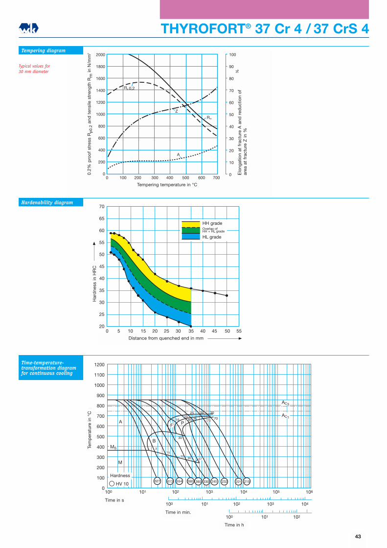
THYROFORT® 37 Cr 4 / 37 CrS 4
2000
1800
1600
1400
1200
1000
800
600
400
200
0
100
90
80
70
60
50
40
30
20
10
00 100 200 300 400 500 600 700
Rm
Rp 0,2
Z
A
Str
eckg
renz
e R
p 0
,2 u
nd Z
ugfe
stig
keit
Rm in
N/m
m2
Bru
chd
ehnu
ng A
und
Bru
chei
nsch
nüru
ng Z
in %
Anlasstemperatur in oC
Tempering diagram
Typical values for 30 mm diameter
Hardenability diagram
Time-temperature-transformation diagramfor continuous cooling
1200
1100
1000
900
800
700
600
500
400
300
200
100
0
100 101 102
100 101 102 103 104
100 101 102 103 104 105 106
AC3
AC1
MS
A
M
HV 10
10
30
315
70
B
95 57
F P
1585
25
75
30 30
7070
613 554 390 360 330 245 232 221 210627
Tem
per
atur
in o
C
Zeit in s
Zeit in min
Zeit in h
Härtewerte
70
65
60
55
50
45
40
35
30
25
200 5 10 15 20 25 30 35 40 45 50 55
Abstand von der abgeschreckten Stirnfläche in mm
Här
te in
HR
C
HH-SorteÜberschneidungHH+HL-Sorte
HL-Sorte
43
Elo
ngat
ion
at f
ract
ure
A a
nd r
educ
tion
of
area
at
frac
ture
Z in
%
0.2%
pro
of
stre
ss R
p0.
2an
d t
ensi
le s
tren
gth
Rm
in N
/mm
2
Tempering temperature in °C
Har
dne
ss in
HR
C
Distance from quenched end in mm
Time in s
Time in min.
Time in h
Tem
per
atur
e in
°C
Hardness
HH gradeOverlap ofHH + HL grade
HL grade
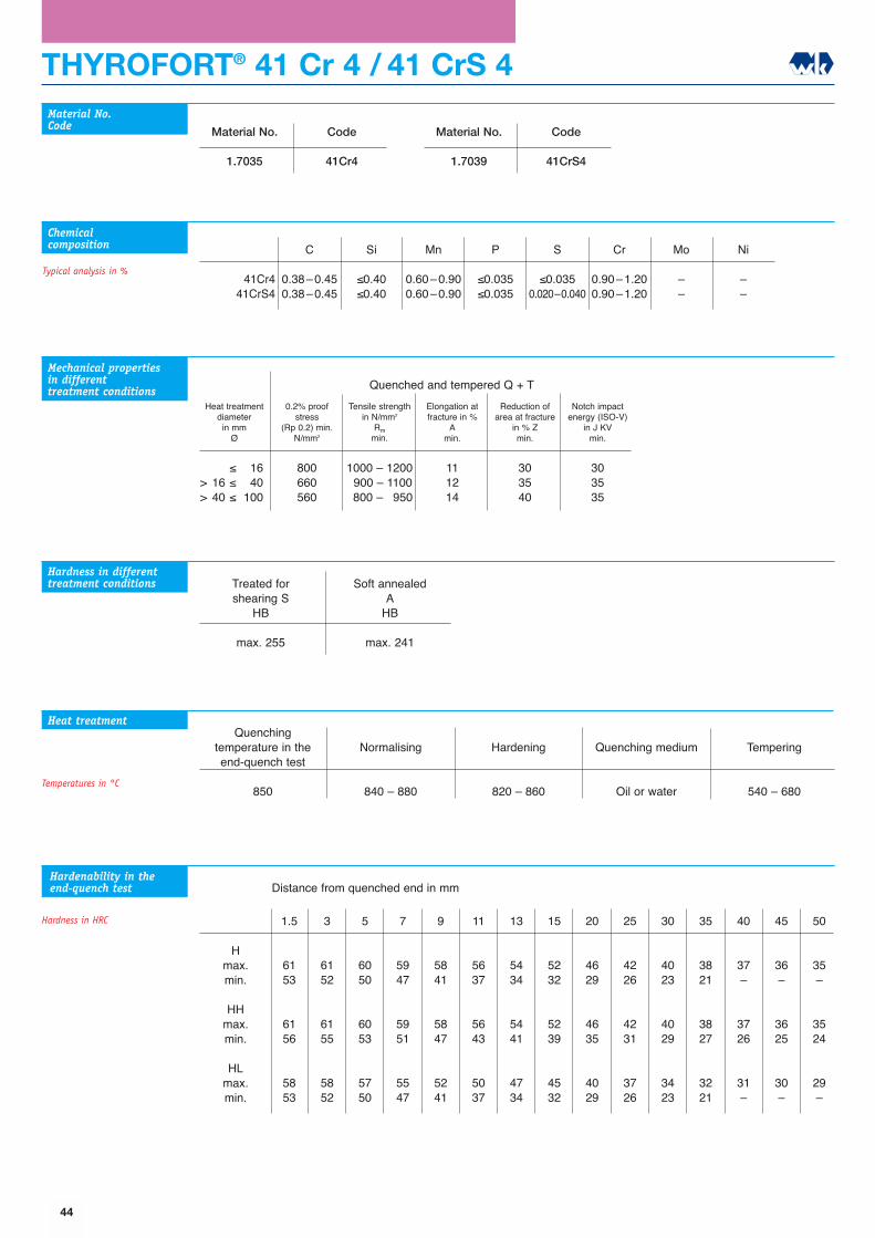
THYROFORT® 41 Cr 4 / 41 CrS 4
Quenching temperature in theend-quench test
850
Normalising
840 � 880
Hardening
820 � 860
Quenching medium
Oil or water
Tempering
540 � 680
Material No.
1.7035
Code
41Cr4
C
0.38�0.450.38�0.45
Si
≤0.40≤0.40
Mn
0.60�0.900.60�0.90
P
≤0.035≤0.035
S
≤0.0350.020�0.040
Cr
0.90�1.200.90�1.20
Mo
��
Ni
��
41Cr441CrS4
Material No.Code
Chemicalcomposition
Heat treatment
Typical analysis in %
Material No.
1.7039
Code
41CrS4
1.5
6153
6156
5853
3
6152
6155
5852
5
6050
6053
5750
7
5947
5951
5547
9
5841
5847
5241
11
5637
5643
5037
13
5434
5441
4734
15
5232
5239
4532
20
4629
4635
4029
25
4226
4231
3726
30
4023
4029
3423
35
3821
3827
3221
40
37�
3726
31�
45
36�
3625
30�
50
35�
3524
29�
Hmax.min.
HHmax.min.
HLmax.min.
Hardenability in theend-quench test
Hardness in HRC
Mechanical properties in differenttreatment conditions
Heat treatmentdiameter
in mmØ
0.2% proofstress
(Rp 0.2) min.N/mm2
Tensile strengthin N/mm2
Rmmin.
Elongation atfracture in %
Amin.
Reduction ofarea at fracture
in % Zmin.
Notch impactenergy (ISO-V)
in J KVmin.
≤ 16> 16 ≤ 40> 40 ≤ 100
800660560
1000 � 12001900 � 11001800 � 1950
111214
303540
303535
Quenched and tempered Q + T
Hardness in differenttreatment conditions Treated for
shearing SHB
max. 255
Soft annealedA
HB
max. 241
Temperatures in °C
Distance from quenched end in mm
44
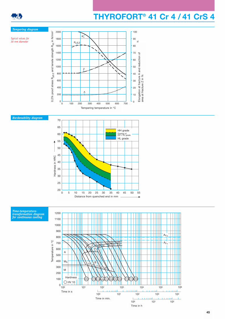
1200
1100
1000
900
800
700
600
500
400
300
200
100
0100 101 102 103 104 105 106
100 101 102 103 104
100 101 102
AC3
AC1
M
MS
A
HV 10
85 808020
802015
90
10
90
B
FP
3075 92
3
5
5
10
629 579 263 236 215 210 206510 428 293312
20
Tem
per
atur
in o
C
Zeit in s
Zeit in min
Zeit in h
Härtewerte
THYROFORT® 41 Cr 4 / 41 CrS 4
2000
1800
1600
1400
1200
1000
800
600
400
200
0
100
90
80
70
60
50
40
30
20
10
00 100 200 300 400 500 600 700
Rm
Rp 0,2
Z
AStr
eckg
renz
e R
p 0
,2 u
nd Z
ugfe
stig
keit
Rm in
N/m
m2
Bru
chd
ehnu
ng A
und
Bru
chei
nsch
nüru
ng Z
in %
Anlasstemperatur in oC
Tempering diagram
Typical values for 30 mm diameter
Hardenability diagram
Time-temperature-transformation diagramfor continuous cooling
70
65
60
55
50
45
40
35
30
25
200 5 10 15 20 25 30 35 40 45 50 55
Abstand von der abgeschreckten Stirnfläche in mm
Här
te in
HR
C
HH-SorteÜberschneidungHH+HL-Sorte
HL-Sorte
45
Elo
ngat
ion
at f
ract
ure
A a
nd r
educ
tion
of
area
at
frac
ture
Z in
%
0.2%
pro
of
stre
ss R
p0.
2an
d t
ensi
le s
tren
gth
Rm
in N
/mm
2
Tempering temperature in °C
Har
dne
ss in
HR
C
Distance from quenched end in mm
Time in s
Time in min.
Time in h
Tem
per
atur
e in
°C
Hardness
HH gradeOverlap ofHH + HL grade
HL grade
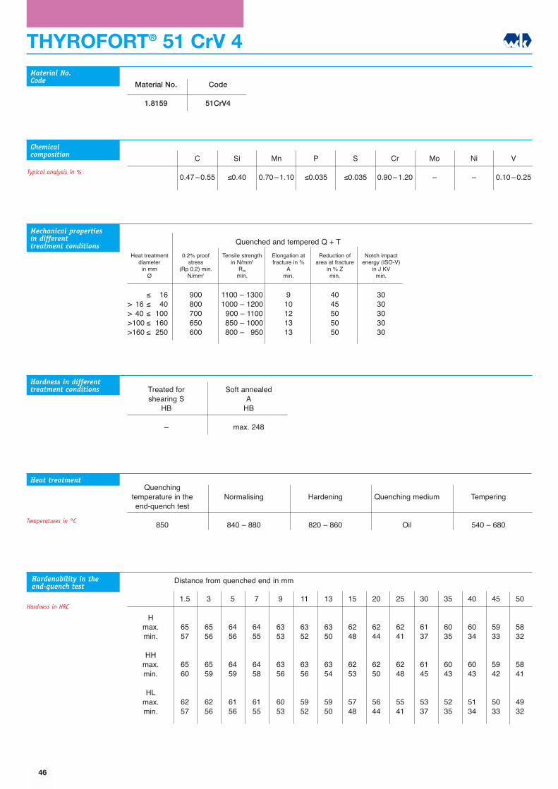
THYROFORT® 51 CrV 4
Quenching temperature in theend-quench test
850
Normalising
840 � 880
Hardening
820 � 860
Quenching medium
Oil
Tempering
540 � 680
Material No.
1.8159
Code
51CrV4
C
0.47�0.55
Si
≤0.40
Mn
0.70�1.10
P
≤0.035
S
≤0.035
Cr
0.90�1.20
Mo
�
Ni
�
V
0.10�0.25
Material No.Code
Chemicalcomposition
Heat treatment
Typical analysis in %
1.5
6557
6560
6257
3
6556
6559
6256
5
6456
6459
6156
7
6455
6458
6155
9
6353
6356
6053
11
6352
6356
5952
13
6350
6354
5950
15
6248
6253
5748
20
6244
6250
5644
25
6241
6248
5541
30
6137
6145
5337
35
6035
6043
5235
40
6034
6043
5134
45
5933
5942
5033
50
5832
5841
4932
Hmax.min.
HHmax.min.
HLmax.min.
Hardenability in theend-quench test
Hardness in HRC
Mechanical properties in differenttreatment conditions
Heat treatmentdiameter
in mmØ
0.2% proofstress
(Rp 0.2) min.N/mm2
Tensile strengthin N/mm2
Rmmin.
Elongation atfracture in %
Amin.
Reduction ofarea at fracture
in % Zmin.
Notch impactenergy (ISO-V)
in J KVmin.
≤ 16> 16 ≤ 40> 40 ≤ 100>100 ≤ 160>160 ≤ 250
900800700650600
1100 � 13001000 � 12001900 � 11001850 � 10001800 � 1950
910121313
4045505050
3030303030
Quenched and tempered Q + T
Hardness in differenttreatment conditions Treated for
shearing SHB
�
Soft annealedA
HB
max. 248
Temperatures in °C
Distance from quenched end in mm
46
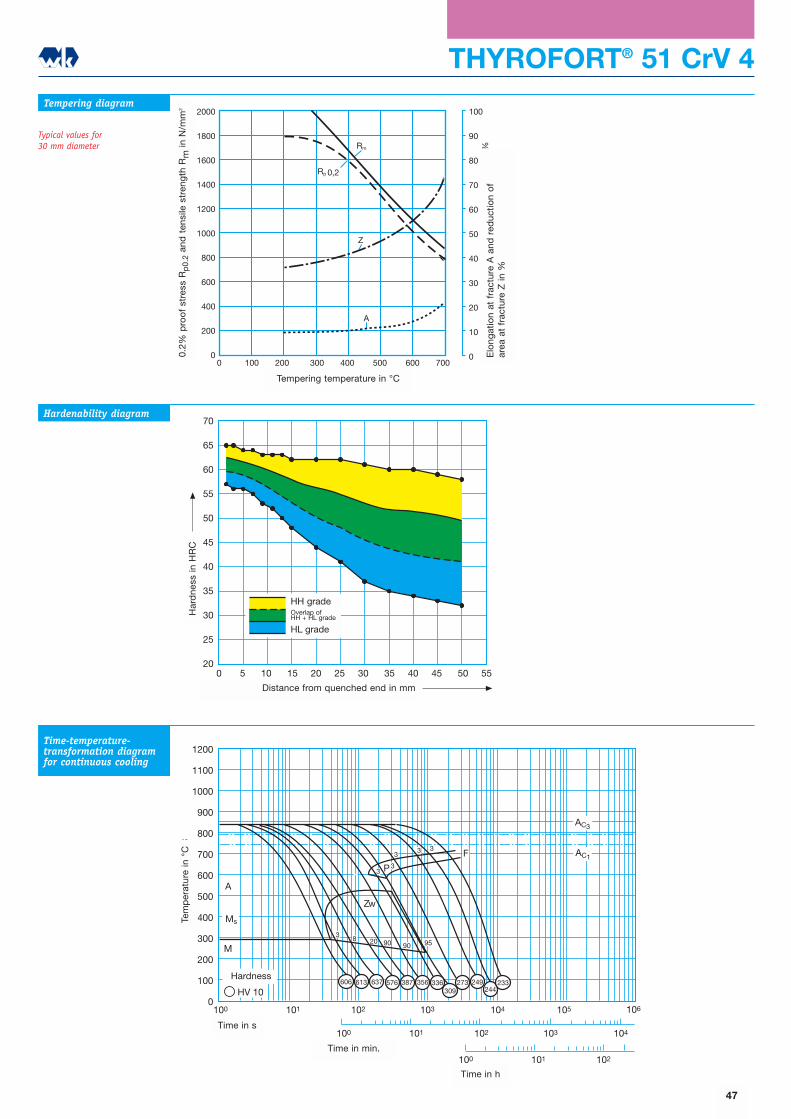
1200
1100
1000
900
800
700
600
500
400
300
200
100
0100 101 102 103 104 105 106
100 101 102 103 104
100 101 102
AC1
AC3
M
Ms
A
HV 10
20
Zw
F
P
3 8
3
90 90 95
33 3
3
387 356309
273 249606 613 576637 336244
233
Tem
per
atur
in o
C
Zeit in s
Zeit in min
Zeit in h
Härtewerte
THYROFORT® 51 CrV 4
2000
1800
1600
1400
1200
1000
800
600
400
200
0
100
90
80
70
60
50
40
30
20
10
00 100 200 300 400 500 600 700
Rm
Rp 0,2
Z
A
Str
eckg
renz
e R
p 0
,2 u
nd Z
ugfe
stig
keit
Rm in
N/m
m2
Bru
chd
ehnu
ng A
und
Bru
chei
nsch
nüru
ng Z
in %
Anlasstemperatur in oC
Tempering diagram
Typical values for 30 mm diameter
Hardenability diagram
Time-temperature-transformation diagramfor continuous cooling
70
65
60
55
50
45
40
35
30
25
200 5 10 15 20 25 30 35 40 45 50 55
Abstand von der abgeschreckten Stirnfläche in mm
Här
te in
HR
C
HH-SorteÜberschneidungHH+HL-Sorte
HL-Sorte
47
Elo
ngat
ion
at f
ract
ure
A a
nd r
educ
tion
of
area
at
frac
ture
Z in
%
0.2%
pro
of
stre
ss R
p0.
2an
d t
ensi
le s
tren
gth
Rm
in N
/mm
2
Tempering temperature in °C
Har
dne
ss in
HR
C
Distance from quenched end in mm
Time in s
Time in min.
Time in h
Tem
per
atur
e in
°C
Hardness
HH gradeOverlap ofHH + HL grade
HL grade
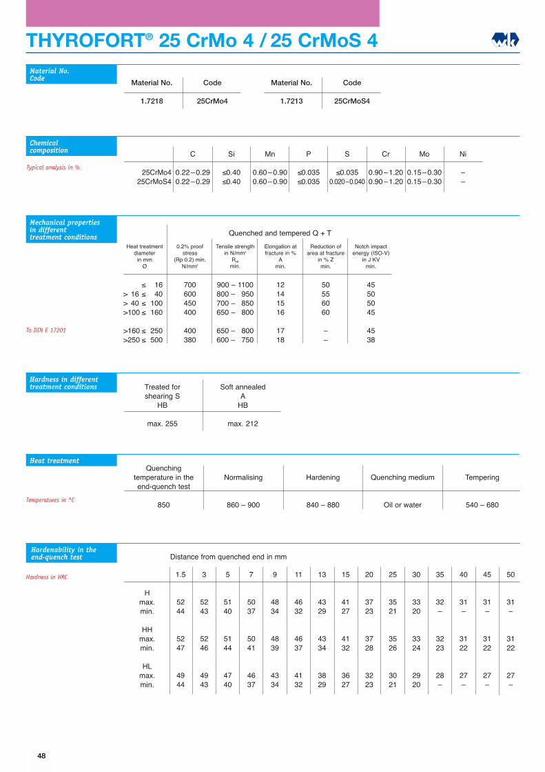
THYROFORT® 25 CrMo 4 / 25 CrMoS 4
Quenching temperature in theend-quench test
850
Normalising
860 � 900
Hardening
840 � 880
Quenching medium
Oil or water
Tempering
540 � 680
Material No.
1.7218
Code
25CrMo4
C
0.22�0.290.22�0.29
Si
≤0.40≤0.40
Mn
0.60�0.900.60�0.90
P
≤0.035≤0.035
S
≤0.0350.020�0.040
Cr
0.90�1.200.90�1.20
Mo
0.15�0.300.15�0.30
Ni
��
25CrMo425CrMoS4
Material No.Code
Chemicalcomposition
Heat treatment
Typical analysis in %
Material No.
1.7213
Code
25CrMoS4
1.5
5244
5247
4944
3
5243
5246
4943
5
5140
5144
4740
7
5037
5041
4637
9
4834
4839
4334
11
4632
4637
4132
13
4329
4334
3829
15
4127
4132
3627
20
3723
3728
3223
25
3521
3526
3021
30
3320
3324
2920
35
32�
3223
28�
40
31�
3122
27�
45
31�
3122
27�
50
31�
3122
27�
Hmax.min.
HHmax.min.
HLmax.min.
Hardenability in theend-quench test
Hardness in HRC
Mechanical properties in differenttreatment conditions
Heat treatmentdiameter
in mmØ
0.2% proofstress
(Rp 0.2) min.N/mm2
Tensile strengthin N/mm2
Rmmin.
Elongation atfracture in %
Amin.
Reduction ofarea at fracture
in % Zmin.
Notch impactenergy (ISO-V)
in J KVmin.
≤ 16> 16 ≤ 40> 40 ≤ 100>100 ≤ 160
>160 ≤ 250>250 ≤ 500
700600450400
400380
900 � 1100800 � 1950700 � 1850650 � 1800
650 � 1800600 � 1750
12141516
1718
50556060
��
45505045
4538
Quenched and tempered Q + T
Hardness in differenttreatment conditions Treated for
shearing SHB
max. 255
Soft annealedA
HB
max. 212
To DIN E 17201
Temperatures in °C
Distance from quenched end in mm
48
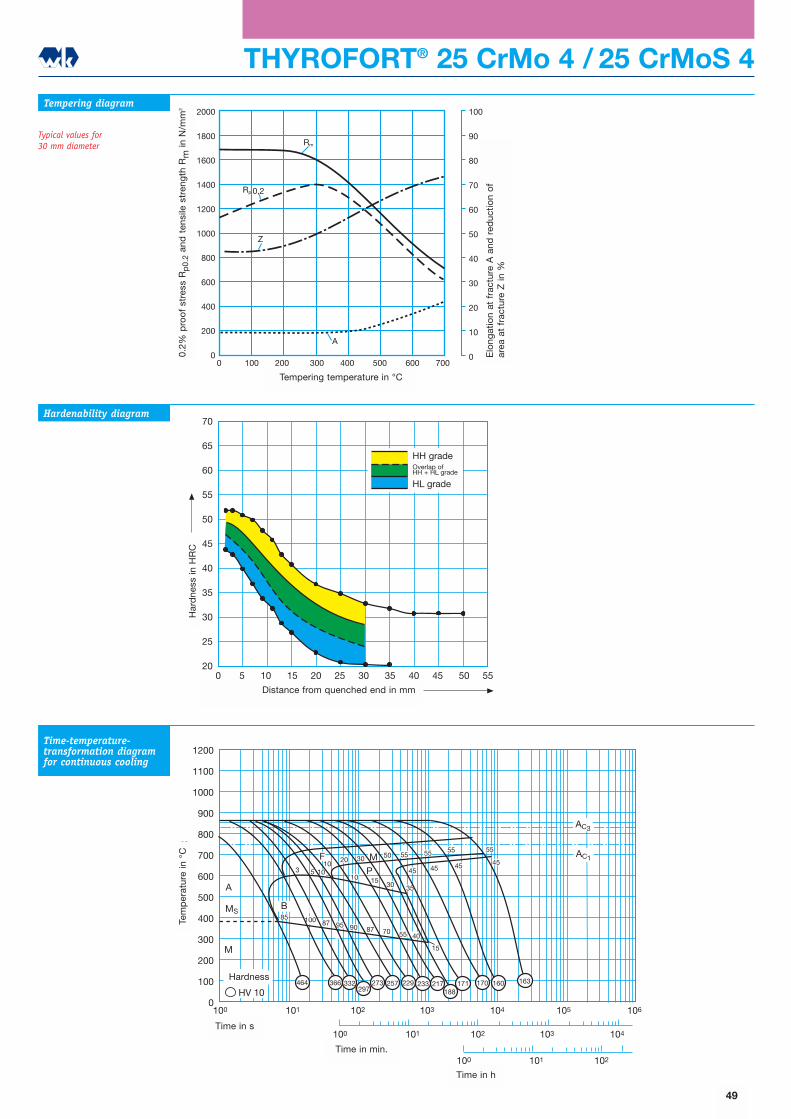
1200
1100
1000
900
800
700
600
500
400
300
200
100
0100 101 102 103 104 105 106
100 101 102 103 104
100 101 102
AC1
AC3
MS
A
B
M
HV 10
30
3
87
F
P
85
9070 55
100 87 95
40
M
5 1010
2050 55 55 55 55
45454545
35
15
301510
229188
366 332 257273 217 160464 163297
233 171 170
Tem
per
atur
in o
C
Zeit in s
Zeit in min
Zeit in h
Härtewerte
THYROFORT® 25 CrMo 4 / 25 CrMoS 4
2000
1800
1600
1400
1200
1000
800
600
400
200
0
100
90
80
70
60
50
40
30
20
10
00 100 200 300 400 500 600 700
Rm
Rp 0,2
Z
A
Str
eckg
renz
e R
p 0
,2 u
nd Z
ugfe
stig
keit
Rm in
N/m
m2
Bru
chd
ehnu
ng A
und
Bru
chei
nsch
nüru
ng Z
in %
Anlasstemperatur in oC
Tempering diagram
Typical values for 30 mm diameter
Hardenability diagram
Time-temperature-transformation diagramfor continuous cooling
70
65
60
55
50
45
40
35
30
25
200 5 10 15 20 25 30 35 40 45 50 55
Abstand von der abgeschreckten Stirnfläche in mm
Här
te in
HR
C
HH-SorteÜberschneidungHH+HL-Sorte
HL-Sorte
49
Elo
ngat
ion
at f
ract
ure
A a
nd r
educ
tion
of
area
at
frac
ture
Z in
%
0.2%
pro
of
stre
ss R
p0.
2an
d t
ensi
le s
tren
gth
Rm
in N
/mm
2
Tempering temperature in °C
Har
dne
ss in
HR
C
Distance from quenched end in mm
Time in s
Time in min.
Time in h
Tem
per
atur
e in
°C
Hardness
HH gradeOverlap ofHH + HL grade
HL grade
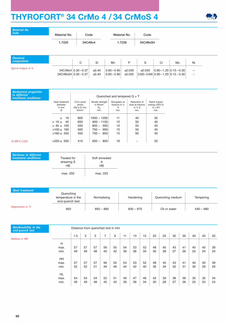
THYROFORT® 34 CrMo 4 / 34 CrMoS 4
Quenching temperature in theend-quench test
850
Normalising
850 � 890
Hardening
830 � 870
Quenching medium
Oil or water
Tempering
540 � 680
Material No.
1.7220
Code
34CrMo4
C
0.30�0.370.30�0.37
Si
≤0.40≤0.40
Mn
0.60�0.900.60�0.90
P
≤0.035≤0.035
S
≤0.0350.020�0.040
Cr
0.90�1.200.90�1.20
Mo
0.15 � 0.300.15 � 0.30
Ni
��
34CrMo434CrMoS4
Material No.Code
Chemicalcomposition
Heat treatment
Typical analysis in %
Material No.
1.7226
Code
34CrMoS4
1.5
5749
5752
5449
3
5749
5752
5449
5
5748
5751
5448
7
5645
5649
5245
9
5542
5546
5142
11
5439
5444
4939
13
5336
5342
4736
15
5234
5240
4634
20
4830
4836
4230
25
4528
4534
3928
30
4327
4332
3827
35
4126
4131
3626
40
4025
4030
3525
45
4024
4029
3524
50
3924
3929
3424
Hmax.min.
HHmax.min.
HLmax.min.
Hardenability in theend-quench test
Hardness in HRC
Mechanical properties in differenttreatment conditions
Heat treatmentdiameter
in mmØ
0.2% proofstress
(Rp 0.2) min.N/mm2
Tensile strengthin N/mm2
Rmmin.
Elongation atfracture in %
Amin.
Reduction ofarea at fracture
in % Zmin.
Notch impactenergy (ISO-V)
in J KVmin.
≤ 16> 16 ≤ 40> 40 ≤ 100>100 ≤ 160>160 ≤ 250
>250 ≤ 500
800650550500450
410
1000 � 12001900 � 11001800 � 19501750 � 19001700 � 1850
650 � 1800
1112141515
16
4550555560
�
3540454540
33
Quenched and tempered Q + T
Hardness in differenttreatment conditions Treated for
shearing SHB
max. 255
Soft annealedA
HB
max. 223
To DIN E 17201
Temperatures in °C
Distance from quenched end in mm
50
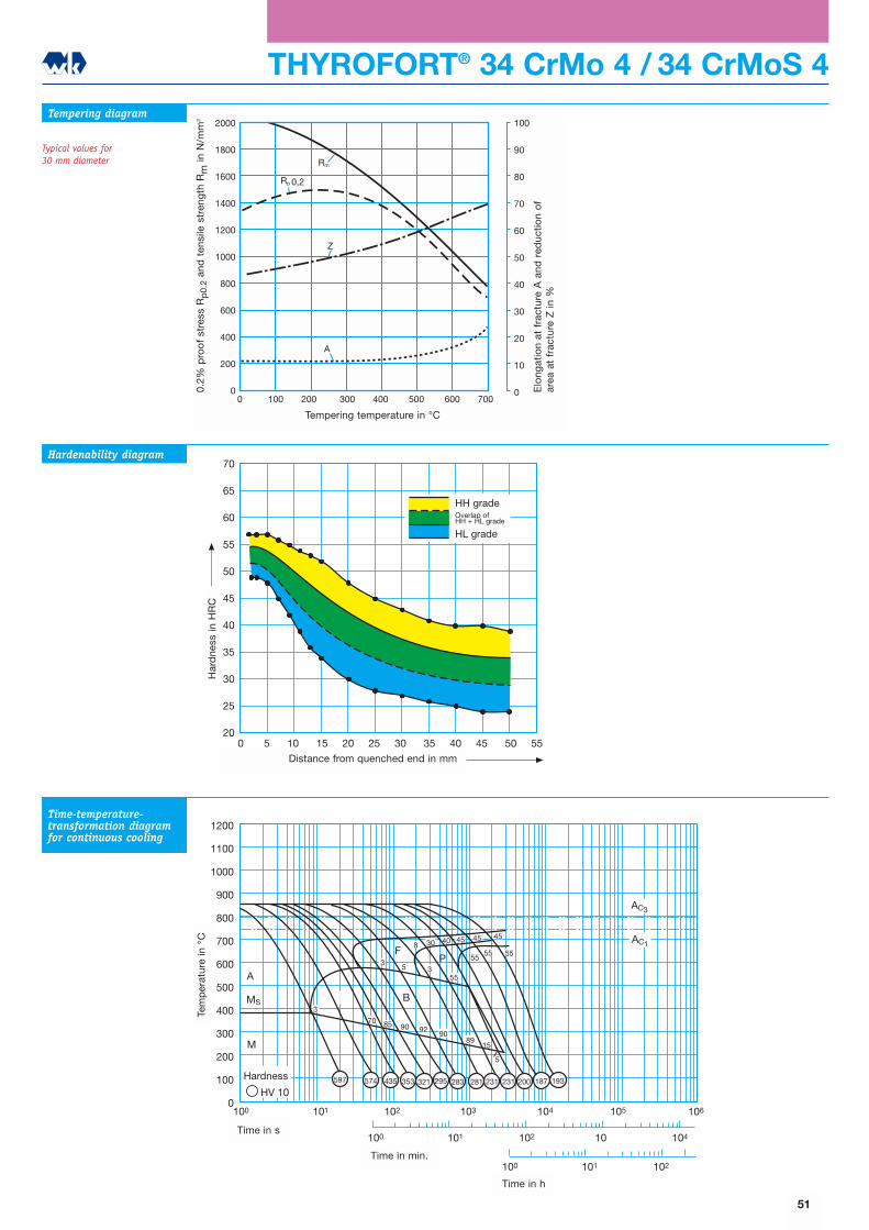
100 101 102
0 2 410 101 10 10 10
100 10 102 10 10 105 1061 3 4
1200
1100
1000
900
800
700
600
500
400
300
200
100
0
AC3
AC1
M
A
MS
HV 10
45
90
B
F
8592 90
70
89
30 40 45
5555
55
15
3
5
5
845
55
3
3
P
295574 353 281597 435 283 231 200231 187 193321
Tem
per
atur
ino C
Zeit in s
Zeit in min
Zeit in h
Härtewerte
THYROFORT® 34 CrMo 4 / 34 CrMoS 4
2000
1800
1600
1400
1200
1000
800
600
400
200
0
100
90
80
70
60
50
40
30
20
10
00 100 200 300 400 500 600 700
Rm
Rp 0,2
Z
A
Str
eckg
renz
e R
p 0
,2 u
nd Z
ugfe
stig
keit
Rm in
N/m
m2
Bru
chd
ehnu
ng A
und
Bru
chei
nsch
nüru
ng Z
in %
Anlasstemperatur in oC
Tempering diagram
Typical values for 30 mm diameter
Hardenability diagram
Time-temperature-transformation diagramfor continuous cooling
70
65
60
55
50
45
40
35
30
25
200 5 10 15 20 25 30 35 40 45 50 55
Abstand von der abgeschreckten Stirnfläche in mm
Här
te in
HR
C
HH-SorteÜberschneidungHH+HL-Sorte
HL-Sorte
51
Elo
ngat
ion
at f
ract
ure
A a
nd r
educ
tion
of
area
at
frac
ture
Z in
%
0.2%
pro
of
stre
ss R
p0.
2an
d t
ensi
le s
tren
gth
Rm
in N
/mm
2
Tempering temperature in °C
Har
dne
ss in
HR
C
Distance from quenched end in mm
Time in s
Time in min.
Time in h
Tem
per
atur
e in
°C
Hardness
HH gradeOverlap ofHH + HL grade
HL grade

THYROFORT® 42 CrMo 4 / 42 CrMoS 4
Quenching temperature in theend-quench test
850
Normalising
840 � 880
Hardening
820 � 860
Quenching medium
Oil or water
Tempering
540 � 680
Material No.
1.7225
Code
42CrMo4
C
0.38�0.450.38�0.45
Si
≤0.40≤0.40
Mn
0.60�0.900.60�0.90
P
≤0.035≤0.035
S
≤0.0350.020�0.040
Cr
0.90�1.200.90�1.20
Mo
0.15 � 0.300.15 � 0.30
Ni
��
42CrMo442CrMoS4
Material No.Code
Chemicalcomposition
Heat treatment
Typical analysis in %
Material No.
1.7227
Code
42CrMoS4
1.5
6153
6156
5853
3
6153
6156
5853
5
6152
6155
5852
7
6051
6054
5751
9
6049
6052
5649
11
5943
5948
5443
13
5940
5946
5340
15
5837
5844
5137
20
5634
5641
4934
25
5332
5339
4632
30
5131
5138
4431
35
4830
4836
4230
40
4730
4736
4130
45
4629
4635
4029
50
4529
4534
4029
Hmax.min.
HHmax.min.
HLmax.min.
Hardenability in theend-quench test
Hardness in HRC
Mechanical properties in differenttreatment conditions
Heat treatmentdiameter
in mmØ
0.2% proofstress
(Rp 0.2) min.N/mm2
Tensile strengthin N/mm2
Rmmin.
Elongation atfracture in %
Amin.
Reduction ofarea at fracture
in % Zmin.
Notch impactenergy (ISO-V)
in J KVmin.
≤ 16> 16 ≤ 40> 40 ≤ 100>100 ≤ 160>160 ≤ 250
>250 ≤ 500>500 ≤ 750
900750650550500
460390
1100 � 13001000 � 12001900 � 11001800 � 19501750 � 1900
1700 � 18501600 � 1750
1011121314
1516
4045505055
��
3035353535
2722
Quenched and tempered Q + T
Hardness in differenttreatment conditions Treated for
shearing SHB
max. 255
Soft annealedA
HB
max. 241
To DIN E 17201
Temperatures in °C
Distance from quenched end in mm
52
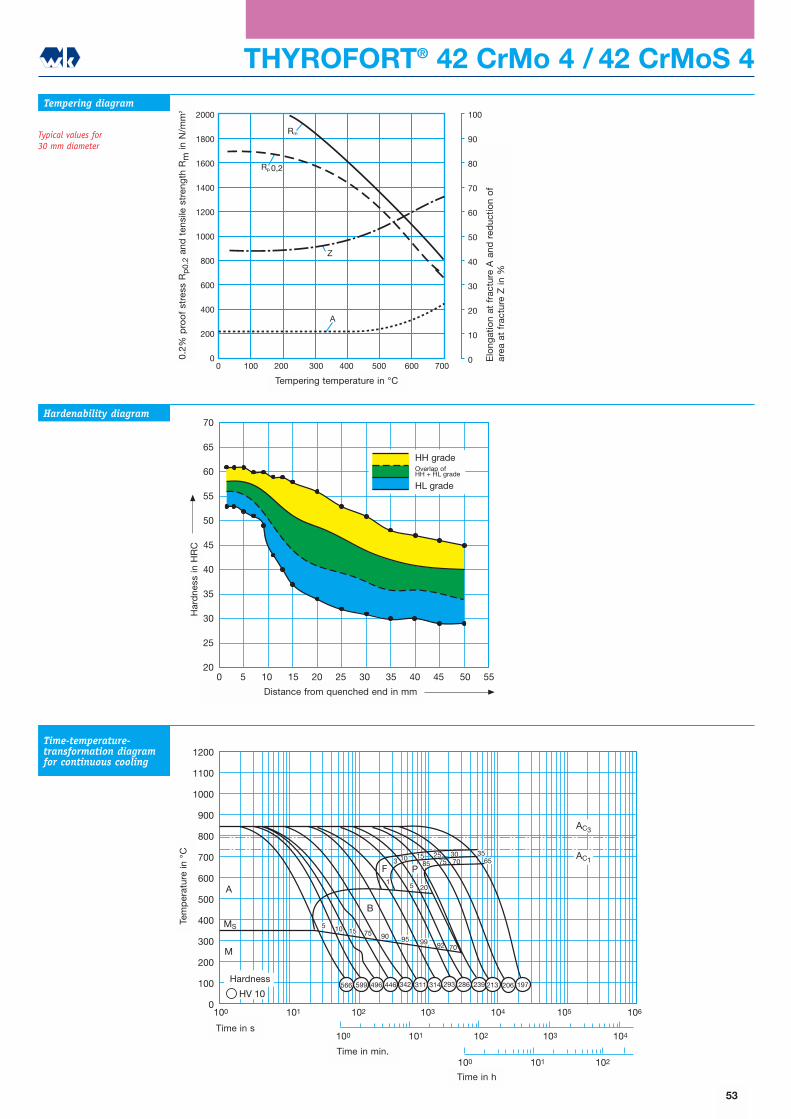
1200
1100
1000
900
800
700
600
500
400
300
200
100
0100 101 102 103 104 105
100 101 102 103 104
100 101 102
106
AC1
AC3
M
MS
A
HV 10
3015
15
B
F
1090 95
92
3 10 257075
5
70
20
P1
3565
99
575
342566 496 293599 311 239 206446 314 213 197286
85
Tem
per
atur
in o
C
Zeit in s
Zeit in min
Zeit in h
Härtewerte
THYROFORT® 42 CrMo 4 / 42 CrMoS 4
2000
1800
1600
1400
1200
1000
800
600
400
200
0
100
90
80
70
60
50
40
30
20
10
00 100 200 300 400 500 600 700
Rm
Rp 0,2
Z
A
Str
eckg
renz
e R
p 0
,2 u
nd Z
ugfe
stig
keit
Rm in
N/m
m2
Bru
chd
ehnu
ng A
und
Bru
chei
nsch
nüru
ng Z
in %
Anlasstemperatur in oC
Tempering diagram
Typical values for 30 mm diameter
Hardenability diagram
Time-temperature-transformation diagramfor continuous cooling
70
65
60
55
50
45
40
35
30
25
200 5 10 15 20 25 30 35 40 45 50 55
Abstand von der abgeschreckten Stirnfläche in mm
Här
te in
HR
C
HH-SorteÜberschneidungHH+HL-Sorte
HL-Sorte
53
Elo
ngat
ion
at f
ract
ure
A a
nd r
educ
tion
of
area
at
frac
ture
Z in
%
0.2%
pro
of
stre
ss R
p0.
2an
d t
ensi
le s
tren
gth
Rm
in N
/mm
2
Tempering temperature in °C
Har
dne
ss in
HR
C
Distance from quenched end in mm
Time in s
Time in min.
Time in h
Tem
per
atur
e in
°C
Hardness
HH gradeOverlap ofHH + HL grade
HL grade
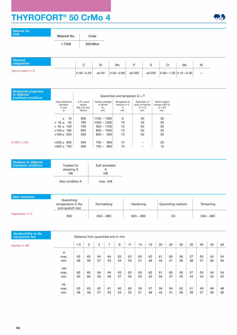
THYROFORT® 50 CrMo 4
Quenching temperature in theend-quench test
850
Normalising
840 � 880
Hardening
820 � 860
Quenching medium
Oil
Tempering
540 � 680
Material No.
1.7228
Code
50CrMo4
C
0.46�0.54
Si
≤0.40
Mn
0.50�0.80
P
≤0.035
S
≤0.035
Cr
0.90�1.20
Mo
0.15 � 0.30
Ni
�
Material No.Code
Chemicalcomposition
Heat treatment
Typical analysis in %
1.5
6558
6560
6358
3
6558
6560
6358
5
6457
6459
6257
7
6455
6458
6155
9
6354
6357
6054
11
6353
6356
6053
13
6351
6355
5951
15
6248
6253
5748
20
6145
6150
5645
25
6041
6047
5441
30
5839
5845
5239
35
5738
5744
5138
40
5537
5543
4937
45
5436
5442
4836
50
5436
5442
4836
Hmax.min.
HHmax.min.
HLmax.min.
Hardenability in theend-quench test
Hardness in HRC
Mechanical properties in differenttreatment conditions
Heat treatmentdiameter
in mmØ
0.2% proofstress
(Rp 0.2) min.N/mm2
Tensile strengthin N/mm2
Rmmin.
Elongation atfracture in %
Amin.
Reduction ofarea at fracture
in % Zmin.
Notch impactenergy (ISO-V)
in J KVmin.
≤ 16> 16 ≤ 40> 40 ≤ 100>100 ≤ 160>160 ≤ 250
>250 ≤ 500>500 ≤ 750
900780700650550
540490
1100 � 13001000 � 12001900 � 11001850 � 10001800 � 1950
1750 � 19001700 � 1850
910121313
1415
4045505050
��
3030303030
2015
Quenched and tempered Q + T
Hardness in differenttreatment conditions Treated for
shearing SHB
See condition A
Soft annealedA
HB
max. 248
To DIN E 17201
Temperatures in °C
Distance from quenched end in mm
54
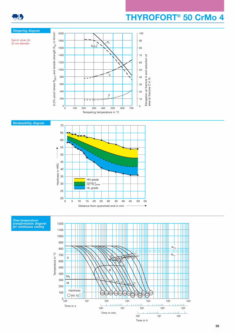
1200
1100
1000
900
800
700
600
500
400
300
200
100
0100 101 102 103 104 105
100 101 102 103 104
100 101 102
106
AC1
AC3
M
MS
A
HV 10
10
10
B
F
580 90 15
3 9090
9087
5
82
P5
92
3
30
95
404599 568635 366243
505 339 255 227325329 285
13 8
1010
Tem
per
atur
in o
C
Zeit in s
Zeit in min
Zeit in h
Härtewerte
THYROFORT® 50 CrMo 4
2000
1800
1600
1400
1200
1000
800
600
400
200
0
100
90
80
70
60
50
40
30
20
10
00 100 200 300 400 500 600 700
Rm
Rp 0,2
Z
A
Str
eckg
renz
e R
p 0
,2 u
nd Z
ugfe
stig
keit
Rm in
N/m
m2
Bru
chd
ehnu
ng A
und
Bru
chei
nsch
nüru
ng Z
in %
Anlasstemperatur in oC
Tempering diagram
Typical values for 30 mm diameter
Hardenability diagram
Time-temperature-transformation diagramfor continuous cooling
70
65
60
55
50
45
40
35
30
25
200 5 10 15 20 25 30 35 40 45 50 55
Abstand von der abgeschreckten Stirnfläche in mm
Här
te in
HR
C
HH-SorteÜberschneidungHH+HL-Sorte
HL-Sorte
55
Elo
ngat
ion
at f
ract
ure
A a
nd r
educ
tion
of
area
at
frac
ture
Z in
%
0.2%
pro
of
stre
ss R
p0.
2an
d t
ensi
le s
tren
gth
Rm
in N
/mm
2
Tempering temperature in °C
Har
dne
ss in
HR
C
Distance from quenched end in mm
Time in s
Time in min.
Time in h
Tem
per
atur
e in
°C
Hardness
HH gradeOverlap ofHH + HL grade
HL grade
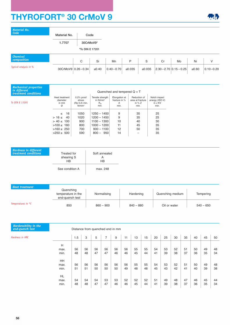
THYROFORT® 30 CrMoV 9
1.5
5648
5651
5448
3
5648
5651
5448
5
5647
5650
5447
7
5647
5650
5347
9
5646
5650
5346
11
5646
5649
5246
13
5545
5548
5245
15
5544
5548
5244
20
5441
5445
5141
25
5339
5343
4939
30
5238
5242
4838
35
5137
5141
4737
40
5036
5040
4636
45
4935
4939
4535
50
4834
4838
4434
Quenching temperature in theend-quench test
850
Normalising
860 � 900
Hardening
840 � 880
Quenching medium
Oil or water
Tempering
540 � 650
Material No.
1.7707
Code
30CrMoV9*
C
0.26�0.34
Si
≤0.40
Mn
0.40�0.70
P
≤0.035
S
≤0.035
Cr
2.30�2.70
Mo
0.15 � 0.25
Ni
≤0.60
V
0.10�0.2030CrMoV9
Material No.Code
Chemicalcomposition
Heat treatment
Typical analysis in %
Hmax.min.
HHmax.min.
HLmax.min.
Hardenability in theend-quench test
Hardness in HRC
Mechanical properties in differenttreatment conditions
Heat treatmentdiameter
in mmØ
0.2% proofstress
(Rp 0.2) min.N/mm2
Tensile strengthin N/mm2
Rmmin.
Elongation atfracture in %
Amin.
Reduction ofarea at fracture
in % Zmin.
Notch impactenergy (ISO-V)
in J KVmin.
≤ 16> 16 ≤ 40> 40 ≤ 100>100 ≤ 160>160 ≤ 250>250 ≤ 500
105010201900180017001590
1250 � 14501200 � 14501100 � 13001000 � 12001900 � 11001800 � 1950
9910111214
3535404550�
252530353535
Quenched and tempered Q + T
Hardness in differenttreatment conditions Treated for
shearing SHB
See condition A
Soft annealedA
HB
max. 248
To DIN E 17201
*To DIN E 17201
Temperatures in °C
Distance from quenched end in mm
56
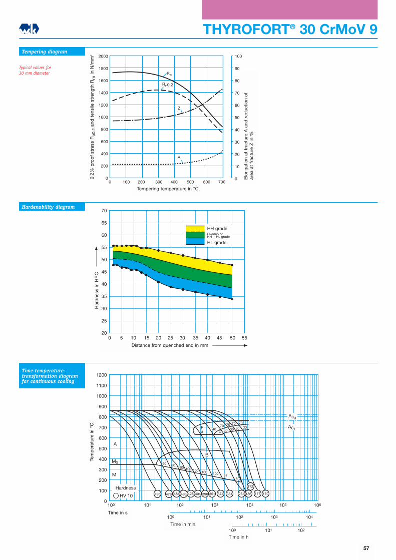
1200
1100
1000
900
800
700
600
500
400
300
200
100
0
100 101 102
100 101 102 103 104
100 101 102 103 104 105 106
AC1
AC3
M
MS
A
HV 10
30
100
70
B
F3
4070
3030P
60
70 70
60100
100 100 100 9760
30
481 493
172
351 351496 478 428 404 390 374 264 186 177 170
Tem
per
atur
in o
C
Zeit in s
Zeit in min
Zeit in h
Härtewerte
2000
1800
1600
1400
1200
1000
800
600
400
200
0
100
90
80
70
60
50
40
30
20
10
00 100 200 300 400 500 600 700
Rm
Rp 0,2
Z
A
Str
eckg
renz
e R
p 0
,2 u
nd Z
ugfe
stig
keit
Rm in
N/m
m2
Bru
chd
ehnu
ng A
und
Bru
chei
nsch
nüru
ng Z
in %
Anlasstemperatur in oC
THYROFORT® 30 CrMoV 9Tempering diagram
Typical values for 30 mm diameter
Hardenability diagram
Time-temperature-transformation diagramfor continuous cooling
70
65
60
55
50
45
40
35
30
25
200 5 10 15 20 25 30 35 40 45 50 55
Abstand von der abgeschreckten Stirnfläche in mm
Här
te in
HR
C
HH-SorteÜberschneidungHH+HL-Sorte
HL-Sorte
57
Elo
ngat
ion
at f
ract
ure
A a
nd r
educ
tion
of
area
at
frac
ture
Z in
%
0.2%
pro
of
stre
ss R
p0.
2an
d t
ensi
le s
tren
gth
Rm
in N
/mm
2
Tempering temperature in °C
Har
dne
ss in
HR
C
Distance from quenched end in mm
Time in s
Time in min.
Time in h
Tem
per
atur
e in
°C
Hardness
HH gradeOverlap ofHH + HL grade
HL grade
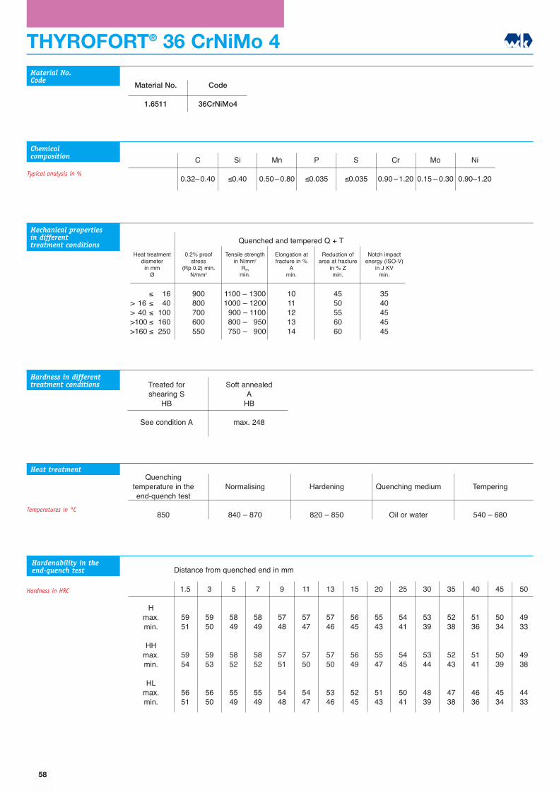
THYROFORT® 36 CrNiMo 4
1.5
5951
5954
5651
3
5950
5953
5650
5
5849
5852
5549
7
5849
5852
5549
9
5748
5751
5448
11
5747
5750
5447
13
5746
5750
5346
15
5645
5649
5245
20
5543
5547
5143
25
5441
5445
5041
30
5339
5344
4839
35
5238
5243
4738
40
5136
5141
4636
45
5034
5039
4534
50
4933
4938
4433
Quenching temperature in theend-quench test
850
Normalising
840 � 870
Hardening
820 � 850
Quenching medium
Oil or water
Tempering
540 � 680
Material No.
1.6511
Code
36CrNiMo4
C
0.32�0.40
Si
≤0.40
Mn
0.50�0.80
P
≤0.035
S
≤0.035
Cr
0.90�1.20
Mo
0.15 � 0.30
Ni
0.90�1.20
Material No.Code
Chemicalcomposition
Heat treatment
Typical analysis in %
Hmax.min.
HHmax.min.
HLmax.min.
Hardenability in theend-quench test
Hardness in HRC
Mechanical properties in differenttreatment conditions
Heat treatmentdiameter
in mmØ
0.2% proofstress
(Rp 0.2) min.N/mm2
Tensile strengthin N/mm2
Rmmin.
Elongation atfracture in %
Amin.
Reduction ofarea at fracture
in % Zmin.
Notch impactenergy (ISO-V)
in J KVmin.
≤ 16> 16 ≤ 40> 40 ≤ 100>100 ≤ 160>160 ≤ 250
900800700600550
1100 � 13001000 � 12001900 � 11001800 � 19501750 � 1900
1011121314
4550556060
3540454545
Quenched and tempered Q + T
Hardness in differenttreatment conditions Treated for
shearing SHB
See condition A
Soft annealedA
HB
max. 248
Temperatures in °C
Distance from quenched end in mm
58
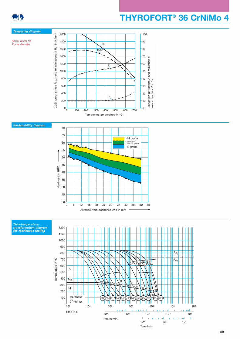
1200
1100
1000
900
800
700
600
500
400
300
200
100
0100 101 102 103 104 105 106
100 101 102 103 104
100 101 102
AC3
AC1
A
MS
M
HV 10
F P3 3 1010 20 25
753
10 B60 80 901009190
97 97 87 70
532 558 517 542 510 438 345 319 297304 274 229286
Tem
per
atur
in °
C
Zeit in s
Zeit in min
Zeit in h
Härtewerte
2000
1800
1600
1400
1200
1000
800
600
400
200
0
100
90
80
70
60
50
40
30
20
10
00 100 200 300 400 500 600 700
Rm
Rp 0,2
Z
A
Str
eckg
renz
e R
p 0
,2 u
nd Z
ugfe
stig
keit
Rm in
N/m
m2
Bru
chd
ehnu
ng A
und
Bru
chei
nsch
nüru
ng Z
in %
Anlasstemperatur in oC
THYROFORT® 36 CrNiMo 4Tempering diagram
Typical values for 60 mm diameter
Hardenability diagram
Time-temperature-transformation diagramfor continuous cooling
70
65
60
55
50
45
40
35
30
25
200 5 10 15 20 25 30 35 40 45 50 55
Abstand von der abgeschreckten Stirnfläche in mm
Här
te in
HR
C
HH-SorteÜberschneidungHH+HL-Sorte
HL-Sorte
59
Elo
ngat
ion
at f
ract
ure
A a
nd r
educ
tion
of
area
at
frac
ture
Z in
%
0.2%
pro
of
stre
ss R
p0.
2an
d t
ensi
le s
tren
gth
Rm
in N
/mm
2
Tempering temperature in °C
Har
dne
ss in
HR
C
Distance from quenched end in mm
Time in s
Time in min.
Time in h
Tem
per
atur
e in
°C
Hardness
HH gradeOverlap ofHH + HL grade
HL grade
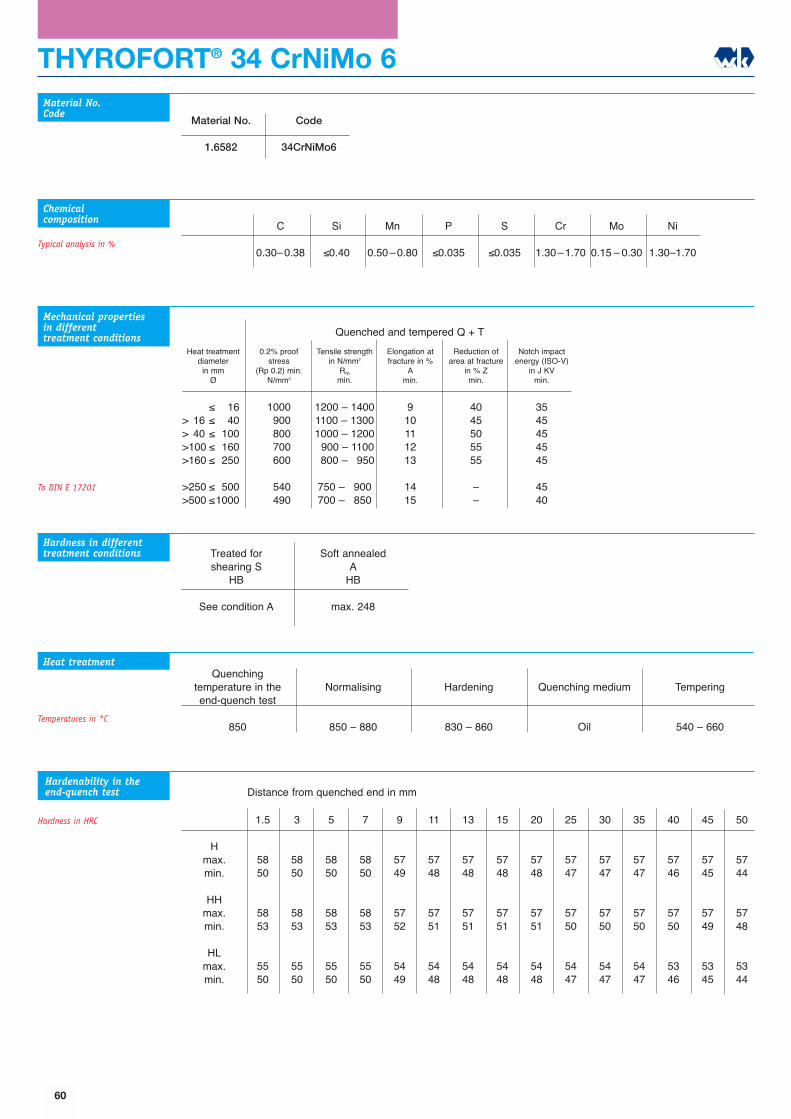
THYROFORT® 34 CrNiMo 6
1.5
5850
5853
5550
3
5850
5853
5550
5
5850
5853
5550
7
5850
5853
5550
9
5749
5752
5449
11
5748
5751
5448
13
5748
5751
5448
15
5748
5751
5448
20
5748
5751
5448
25
5747
5750
5447
30
5747
5750
5447
35
5747
5750
5447
40
5746
5750
5346
45
5745
5749
5345
50
5744
5748
5344
Quenching temperature in theend-quench test
850
Normalising
850 � 880
Hardening
830 � 860
Quenching medium
Oil
Tempering
540 � 660
Material No.
1.6582
Code
34CrNiMo6
C
0.30�0.38
Si
≤0.40
Mn
0.50�0.80
P
≤0.035
S
≤0.035
Cr
1.30�1.70
Mo
0.15 � 0.30
Ni
1.30�1.70
Material No.Code
Chemicalcomposition
Typical analysis in %
Hmax.min.
HHmax.min.
HLmax.min.
Heat treatment
Hardenability in theend-quench test
Hardness in HRC
Mechanical properties in differenttreatment conditions
Heat treatmentdiameter
in mmØ
0.2% proofstress
(Rp 0.2) min.N/mm2
Tensile strengthin N/mm2
Rmmin.
Elongation atfracture in %
Amin.
Reduction ofarea at fracture
in % Zmin.
Notch impactenergy (ISO-V)
in J KVmin.
≤ 16> 16 ≤ 40> 40 ≤ 100>100 ≤ 160>160 ≤ 250
>250 ≤ 500>500 ≤1000
10001900180017001600
15401490
1200 � 14001100 � 13001000 � 12001900 � 11001800 � 1950
750 � 1900700 � 1850
910111213
1415
4045505555
��
3545454545
4540
Quenched and tempered Q + T
Hardness in differenttreatment conditions Treated for
shearing SHB
See condition A
Soft annealedA
HB
max. 248
To DIN E 17201
Temperatures in °C
Distance from quenched end in mm
60
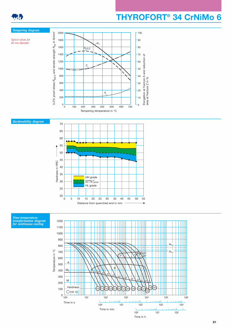
1200
1100
1000
900
800
700
600
500
400
300
200
100
0100 101 102 103 104 105
100 101 102 103 104
100 101 102
106
AC3
AC1
A
MS
M
HV 10
B
4070
923
15 20 30
8085 90
87 82
F 3 8P65
65
35
528 510 505 529 527 483 433 383 349 328 324302
239 202
3215
Tem
per
atur
in o
C
Zeit in s
Zeit in min
Zeit in h
Härtewerte
THYROFORT® 34 CrNiMo 6
2000
1800
1600
1400
1200
1000
800
600
400
200
0
100
90
80
70
60
50
40
30
20
10
00 100 200 300 400 500 600 700
Rm
Z
A
Rp 0,2
Str
eckg
renz
e R
p 0
,2 u
nd Z
ugfe
stig
keit
Rm in
N/m
m2
Bru
chd
ehnu
ng A
und
Bru
chei
nsch
nüru
ng Z
in %
Anlasstemperatur in oC
Tempering diagram
Typical values for 60 mm diameter
Hardenability diagram
Time-temperature-transformation diagramfor continuous cooling
70
65
60
55
50
45
40
35
30
25
200 5 10 15 20 25 30 35 40 45 50 55
Abstand von der abgeschreckten Stirnfläche in mm
Här
te in
HR
C
HH-SorteÜberschneidungHH+HL-Sorte
HL-Sorte
61
Elo
ngat
ion
at f
ract
ure
A a
nd r
educ
tion
of
area
at
frac
ture
Z in
%
0.2%
pro
of
stre
ss R
p0.
2an
d t
ensi
le s
tren
gth
Rm
in N
/mm
2
Tempering temperature in °C
Har
dne
ss in
HR
C
Distance from quenched end in mm
Time in s
Time in min.
Time in h
Tem
per
atur
e in
°C
Hardness
HH gradeOverlap ofHH + HL grade
HL grade

THYROFORT® 30 CrNiMo 8
1.5
5648
5651
5348
3
5648
5651
5348
5
5648
5651
5348
7
5648
5651
5348
9
5547
5550
5247
11
5547
5550
5247
13
5547
5550
5247
15
5546
5549
5246
20
5546
5549
5246
25
5445
5448
5145
30
5445
5448
5145
35
5444
5447
5144
40
5444
5447
5144
45
5443
5447
5043
50
5443
5447
5043
Quenching temperature in theend-quench test
850
Normalising
850 � 880
Hardening
830 � 860
Quenching medium
Oil
Tempering
540 � 660
Material No.
1.6580
Code
30CrNiMo8
C
0.26�0.34
Si
≤0.40
Mn
0.30�0.60
P
≤0.035
S
≤0.035
Cr
1.80�2.20
Mo
0.30 � 0.50
Ni
1.80�2.20
Material No.Code
Chemicalcomposition
Heat treatment
Typical analysis in %
Hmax.min.
HHmax.min.
HLmax.min.
Mechanical properties in differenttreatment conditions
Heat treatmentdiameter
in mmØ
0.2% proofstress
(Rp 0.2) min.N/mm2
Tensile strengthin N/mm2
Rmmin.
Elongation atfracture in %
Amin.
Reduction ofarea at fracture
in % Zmin.
Notch impactenergy (ISO-V)
in J KVmin.
≤ 16> 16 ≤ 40> 40 ≤ 100>100 ≤ 160>160 ≤ 250
>250 ≤ 500>500 ≤1000
10501050190018001700
16301590
1250 � 14501250 � 14501100 � 13001000 � 12001900 � 1100
1850 � 10001800 � 1950
99101112
1212
4040455050
��
3030354545
4540
Quenched and tempered Q + T
Hardness in differenttreatment conditions Treated for
shearing SHB
See condition A
Soft annealedA
HB
max. 248
To DIN E 17201
Hardenability in theend-quench test
Hardness in HRC
Temperatures in °C
Distance from quenched end in mm
62
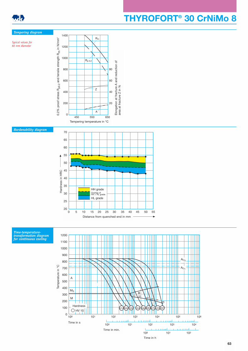
1200
1100
1000
900
800
700
600
500
400
300
200
100
0
100 101 102
100 101 102 103 104
100 101 102 103 104 105 106
AC3
AC1
A
MS
M
HV 10
B2010
60 85 9095
574 552 530 534 560 480 476 433 397
Tem
per
atur
in o
C
Zeit in s
Zeit in min
Zeit in h
Härtewerte
THYROFORT® 30 CrNiMo 8Tempering diagram
Typical values for 60 mm diameter
Hardenability diagram
Time-temperature-transformation diagramfor continuous cooling
70
65
60
55
50
45
40
35
30
25
200 5 10 15 20 25 30 35 40 45 50 55
Abstand von der abgeschreckten Stirnfläche in mm
Här
te in
HR
C
HH-SorteÜberschneidungHH+HL-Sorte
HL-Sorte
1400
1200
1000
800
600
400
200
0450 550 650
80
60
40
20
Z
Rm
Rp 0,2
A
Anlasstemperatur oC
Bru
chd
ehnu
ng A
und
Bru
chei
nsch
nüru
ng Z
in %
Str
eckg
renz
e R
p 0
,2 u
nd Z
ugfe
stig
keit
Rm
in N
/mm
2
63
Elo
ngat
ion
at f
ract
ure
A a
nd r
educ
tion
of
area
at
frac
ture
Z in
%
0.2%
pro
of
stre
ss R
p0.
2an
d t
ensi
le s
tren
gth
Rm
in N
/mm
2
Tempering temperature in °C
Har
dne
ss in
HR
C
Distance from quenched end in mm
Time in s
Time in min.
Time in h
Tem
per
atur
e in
°C
Hardness
HH gradeOverlap ofHH + HL grade
HL grade
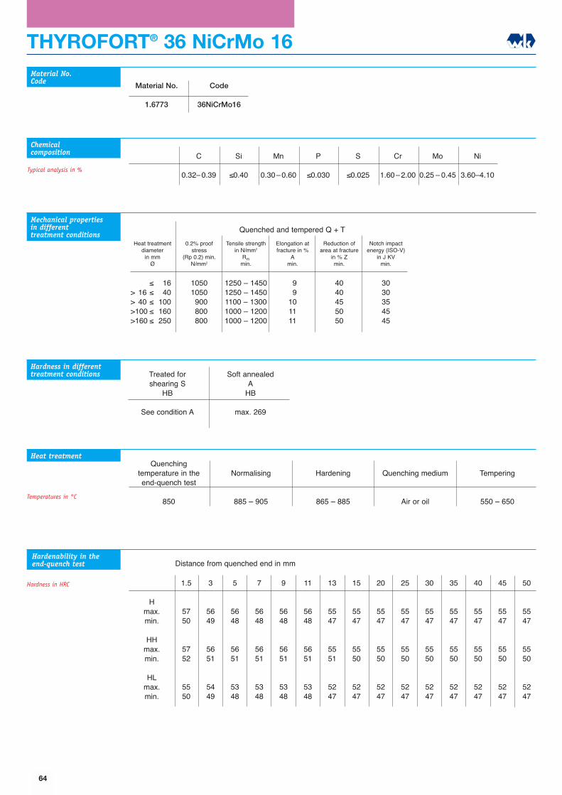
THYROFORT® 36 NiCrMo 16
1.5
5750
5752
5550
3
5649
5651
5449
5
5648
5651
5348
7
5648
5651
5348
9
5648
5651
5348
11
5648
5651
5348
13
5547
5551
5247
15
5547
5550
5247
20
5547
5550
5247
25
5547
5550
5247
30
5547
5550
5247
35
5547
5550
5247
40
5547
5550
5247
45
5547
5550
5247
50
5547
5550
5247
Quenching temperature in theend-quench test
850
Normalising
885 � 905
Hardening
865 � 885
Quenching medium
Air or oil
Tempering
550 � 650
Material No.
1.6773
Code
36NiCrMo16
C
0.32�0.39
Si
≤0.40
Mn
0.30�0.60
P
≤0.030
S
≤0.025
Cr
1.60�2.00
Mo
0.25 � 0.45
Ni
3.60�4.10
Material No.Code
Chemicalcomposition
Heat treatment
Typical analysis in %
Hmax.min.
HHmax.min.
HLmax.min.
Hardenability in theend-quench test
Hardness in HRC
Mechanical properties in differenttreatment conditions
Heat treatmentdiameter
in mmØ
0.2% proofstress
(Rp 0.2) min.N/mm2
Tensile strengthin N/mm2
Rmmin.
Elongation atfracture in %
Amin.
Reduction ofarea at fracture
in % Zmin.
Notch impactenergy (ISO-V)
in J KVmin.
≤ 16> 16 ≤ 40> 40 ≤ 100>100 ≤ 160>160 ≤ 250
10501050190018001800
1250 � 14501250 � 14501100 � 13001000 � 12001000 � 1200
1919101111
4040455050
3030354545
Quenched and tempered Q + T
Hardness in differenttreatment conditions Treated for
shearing SHB
See condition A
Soft annealedA
HB
max. 269
Temperatures in °C
Distance from quenched end in mm
64

THYROFORT® 36 NiCrMo 16
2000
1800
1600
1400
1200
1000
800
600
400
200
0
100
90
80
70
60
50
40
30
20
10
00 100 200 300 400 500 600 700
Rm
Rp 0,2Z
A
Str
eckg
renz
e R
p 0
,2 u
nd Z
ugfe
stig
keit
Rm in
N/m
m2
Bru
chd
ehnu
ng A
und
Bru
chei
nsch
nüru
ng Z
in %
Anlasstemperatur in oC
Tempering diagram
Typical values for120 mm diameter
Hardenability diagram
Time-temperature-transformation diagramfor continuous cooling
70
65
60
55
50
45
40
35
30
25
200 5 10 15 20 25 30 35 40 45 50 55
Abstand von der abgeschreckten Stirnfläche in mm
Här
te in
HR
C
HH-SorteÜberschneidungHH+HL-Sorte
HL-Sorte
1200
1100
1000
900
800
700
600
500
400
300
200
100
0
100 101 102
100 101 102 103 104
100 101 102 103 104 105 106
Ac1e
Ac1b
HV 10
A + K
MS
M
B
RA518 470515 462528 518
Tem
per
atur
in o
C
Zeit in s
Zeit in min
Zeit in h
Härtewerte
65
Elo
ngat
ion
at f
ract
ure
A a
nd r
educ
tion
of
area
at
frac
ture
Z in
%
0.2%
pro
of
stre
ss R
p0.
2an
d t
ensi
le s
tren
gth
Rm
in N
/mm
2
Tempering temperature in °C
Har
dne
ss in
HR
C
Distance from quenched end in mm
Time in s
Time in min.
Time in h
Tem
per
atur
e in
°C
Hardness
HH gradeOverlap ofHH + HL grade
HL grade
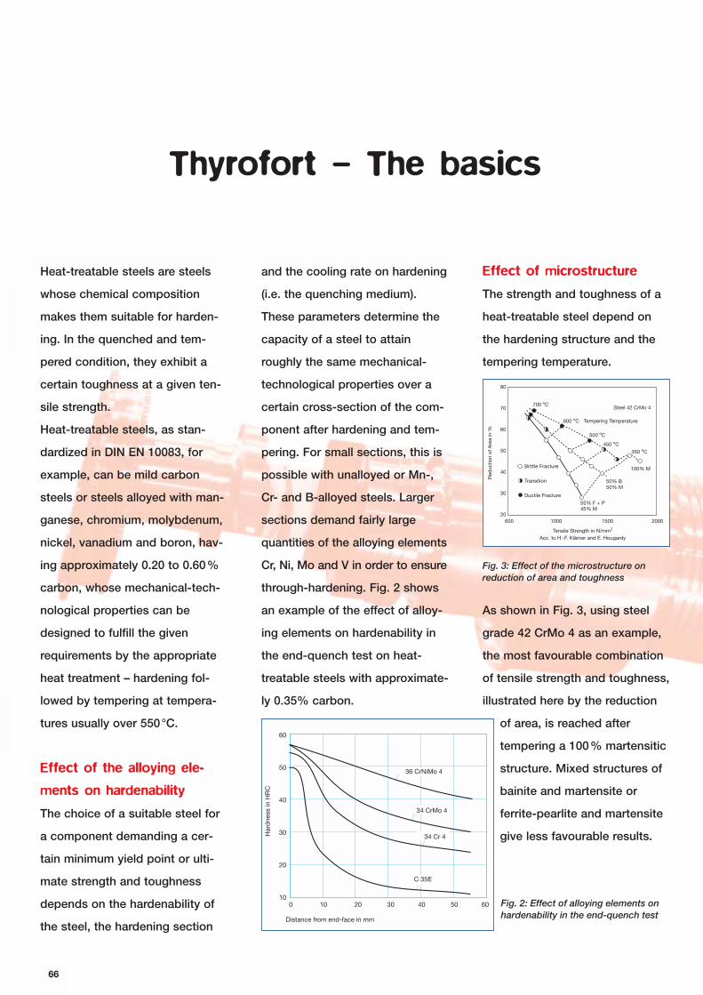
Effect of microstructure
The strength and toughness of a
heat-treatable steel depend on
the hardening structure and the
tempering temperature.
As shown in Fig. 3, using steel
grade 42 CrMo 4 as an example,
the most favourable combination
of tensile strength and toughness,
illustrated here by the reduction
of area, is reached after
tempering a 100% martensitic
structure. Mixed structures of
bainite and martensite or
ferrite-pearlite and martensite
give less favourable results.
66
Thyrofort – The basics
Heat-treatable steels are steels
whose chemical composition
makes them suitable for harden-
ing. In the quenched and tem-
pered condition, they exhibit a
certain toughness at a given ten-
sile strength.
Heat-treatable steels, as stan-
dardized in DIN EN 10083, for
example, can be mild carbon
steels or steels alloyed with man-
ganese, chromium, molybdenum,
nickel, vanadium and boron, hav-
ing approximately 0.20 to 0.60%
carbon, whose mechanical-tech-
nological properties can be
designed to fulfill the given
requirements by the appropriate
heat treatment – hardening fol-
lowed by tempering at tempera-
tures usually over 550°C.
Effect of the alloying ele-
ments on hardenability
The choice of a suitable steel for
a component demanding a cer-
tain minimum yield point or ulti-
mate strength and toughness
depends on the hardenability of
the steel, the hardening section
and the cooling rate on hardening
(i.e. the quenching medium).
These parameters determine the
capacity of a steel to attain
roughly the same mechanical-
technological properties over a
certain cross-section of the com-
ponent after hardening and tem-
pering. For small sections, this is
possible with unalloyed or Mn-,
Cr- and B-alloyed steels. Larger
sections demand fairly large
quantities of the alloying elements
Cr, Ni, Mo and V in order to ensure
through-hardening. Fig. 2 shows
an example of the effect of alloy-
ing elements on hardenability in
the end-quench test on heat-
treatable steels with approximate-
ly 0.35% carbon.
Har
dne
ss in
HR
C
Distance from end-face in mm
60
50
40
30
20
100 10 20 30 40 50 60
34 CrMo 4
34 Cr 4
C 35E
36 CrNiMo 4
Fig. 2: Effect of alloying elements onhardenability in the end-quench test
80
70
60
50
40
30
20600 1000 1500 2000
700 oC
600 oC
500 oC
450 oC
350 oC
100% M
50% B50% M
55% F + P45% M
Tensile Strength in N/mm2
Acc. to H.-F. Klärner and E. Hougardy
Red
uctio
n of
Are
a in
%
Tempering Temperature
Steel 42 CrMo 4
Brittle Fracture
Transition
Ductile Fracture
Fig. 3: Effect of the microstructure on reduction of area and toughness
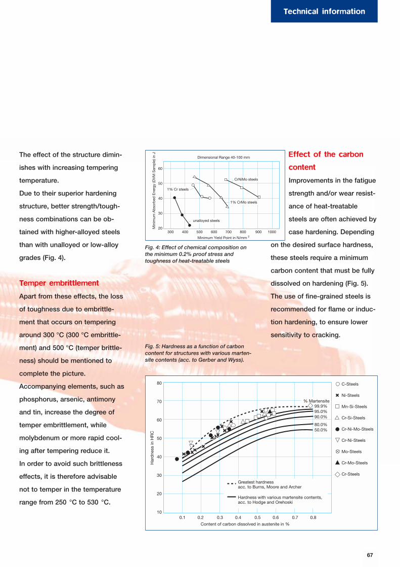
67
The effect of the structure dimin-
ishes with increasing tempering
temperature.
Due to their superior hardening
structure, better strength/tough-
ness combinations can be ob-
tained with higher-alloyed steels
than with unalloyed or low-alloy
grades (Fig. 4).
Temper embrittlement
Apart from these effects, the loss
of toughness due to embrittle-
ment that occurs on tempering
around 300 °C (300 °C embrittle-
ment) and 500 °C (temper brittle-
ness) should be mentioned to
complete the picture.
Accompanying elements, such as
phosphorus, arsenic, antimony
and tin, increase the degree of
temper embrittlement, while
molybdenum or more rapid cool-
ing after tempering reduce it.
In order to avoid such brittleness
effects, it is therefore advisable
not to temper in the temperature
range from 250 °C to 530 °C.
Effect of the carbon
content
Improvements in the fatigue
strength and/or wear resist-
ance of heat-treatable
steels are often achieved by
case hardening. Depending
on the desired surface hardness,
these steels require a minimum
carbon content that must be fully
dissolved on hardening (Fig. 5).
The use of fine-grained steels is
recommended for flame or induc-
tion hardening, to ensure lower
sensitivity to cracking.
Har
dne
ss in
HR
C
Content of carbon dissolved in austenite in %
C-Steels
Ni-Steels
Mn-Si-Steels
Cr-Si-Steels
Cr-Ni-Mo-Steels
Cr-Ni-Steels
Mo-Steels
Cr-Mo-Steels
Cr-Steels
% Martensite
Greatest hardnessacc. to Burns, Moore and Archer
Hardness with various martensite contents,acc. to Hodge and Orehoski
80
70
60
50
40
30
20
100.1 0.2 0.3 0.4 0.5 0.6 0.7 0.8
99.9%95.0%90.0%
80.0%50.0%
Dimensional Range 40-100 mmM
inim
um A
bso
rbed
Ene
rgy
(DV
M S
amp
le) i
n J
Minimum Yield Point in N/mm 2
CrNiMo steels
1% CrMo steels
unalloyed steels
1% Cr steels
60
50
40
30
20300 400 500 600 700 800 900 1000
Fig. 4: Effect of chemical composition onthe minimum 0.2% proof stress andtoughness of heat-treatable steels
Fig. 5: Hardness as a function of carboncontent for structures with various marten-site contents (acc. to Gerber and Wyss).
Technical information
The heat-treatable steels dis-
cussed in this publication are
special engineering steels which
exhibit a higher degree of purity
compared to high-grade steels,
particularly with regard to non-
metallic inclusions, and react uni-
formly to heat treatment. Careful
balancing of the chemical compo-
sition and special manufacturing
and testing conditions allow the
most varied machining and ser-
vice properties to be achieved,
e.g. high or very specific strength
or hardenability in conjunction
with high demands on toughness,
ductility, etc.
Heat-treatable steels are predom-
inantly used for mechanically
highly stressed components, e.g.
in automotive and general me-
chanical engineering.
Forming and machining
Heat-treatable steels exhibit good
hot forming properties. Their cold
workability depends on the car-
bon content, the quantities of
alloying elements and the crys-
talline structure. Heat-treatable
steels intended to be processed
by cold upsetting or cold extru-
sion are usually supplied in the
ASC-annealed condition.
Machinability is mostly influenced
by the strength, the micro-
structure and the non-metallic
inclusions.
In general, it can be said that
machinability deteriorates with
increasing strength and tough-
ness. This is why ferritic-pearlitic
structures, for example, can be
more easily machined than
bainitic or martensitic structures.
In cases involving extensive ma-
chining of components made of
high-strength steels (approx.
>1000 N/mm2), it can thus be
appropriate not to carry out
hardening and tempering until the
part has been pre-machined.
In order to improve machinability,
heat-treatable steels are usually
supplied with a controlled sul-
phur content of 0.020 – 0.040%.
Steels whose machinability has
been improved by special metal-
lurgical treatment can be sup-
plied on request.
68
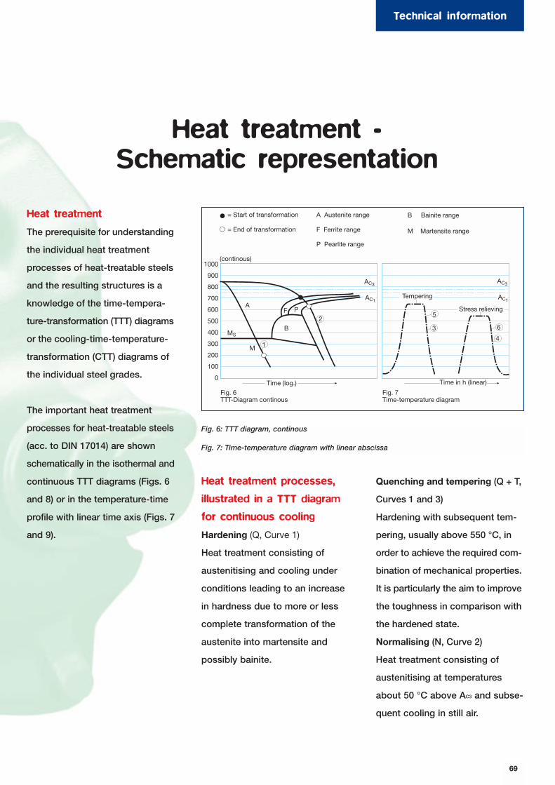
Heat treatment
The prerequisite for understanding
the individual heat treatment
processes of heat-treatable steels
and the resulting structures is a
knowledge of the time-tempera-
ture-transformation (TTT) diagrams
or the cooling-time-temperature-
transformation (CTT) diagrams of
the individual steel grades.
The important heat treatment
processes for heat-treatable steels
(acc. to DIN 17014) are shown
schematically in the isothermal and
continuous TTT diagrams (Figs. 6
and 8) or in the temperature-time
profile with linear time axis (Figs. 7
and 9).
Heat treatment -Schematic representation
(continous)
Tempering
Stress relieving
Fig. 6TTT-Diagram continous
Fig. 7Time-temperature diagram
1000
900
800
700
600
500
400
300
200
100
0Time (log.) Time in h (linear)
A
M 1
B2
F P5
3 6
4
= Start of transformation
= End of transformation
A Austenite range
F Ferrite range
P Pearlite range
B Bainite range
M Martensite range
AC1
AC3
AC1
MS
AC3
Fig. 6: TTT diagram, continous
Fig. 7: Time-temperature diagram with linear abscissa
Heat treatment processes,
illustrated in a TTT diagram
for continuous cooling
Hardening (Q, Curve 1)
Heat treatment consisting of
austenitising and cooling under
conditions leading to an increase
in hardness due to more or less
complete transformation of the
austenite into martensite and
possibly bainite.
Quenching and tempering (Q + T,
Curves 1 and 3)
Hardening with subsequent tem-
pering, usually above 550 °C, in
order to achieve the required com-
bination of mechanical properties.
It is particularly the aim to improve
the toughness in comparison with
the hardened state.
Normalising (N, Curve 2)
Heat treatment consisting of
austenitising at temperatures
about 50 °C above AC3 and subse-
quent cooling in still air.
69
Technical information
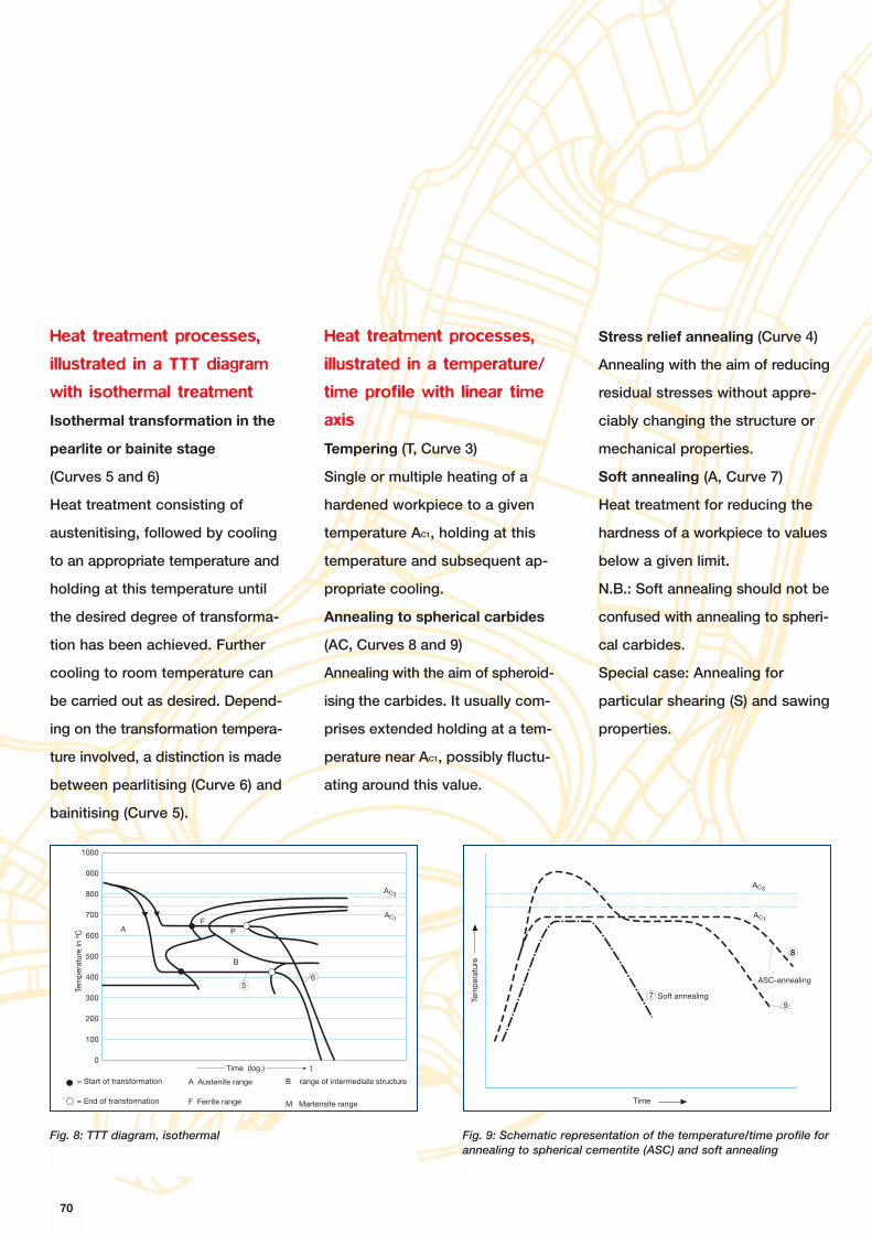
Heat treatment processes,
illustrated in a TTT diagram
with isothermal treatment
Isothermal transformation in the
pearlite or bainite stage
(Curves 5 and 6)
Heat treatment consisting of
austenitising, followed by cooling
to an appropriate temperature and
holding at this temperature until
the desired degree of transforma-
tion has been achieved. Further
cooling to room temperature can
be carried out as desired. Depend-
ing on the transformation tempera-
ture involved, a distinction is made
between pearlitising (Curve 6) and
bainitising (Curve 5).
Heat treatment processes,
illustrated in a temperature/
time profile with linear time
axis
Tempering (T, Curve 3)
Single or multiple heating of a
hardened workpiece to a given
temperature AC1, holding at this
temperature and subsequent ap-
propriate cooling.
Annealing to spherical carbides
(AC, Curves 8 and 9)
Annealing with the aim of spheroid-
ising the carbides. It usually com-
prises extended holding at a tem-
perature near AC1, possibly fluctu-
ating around this value.
Stress relief annealing (Curve 4)
Annealing with the aim of reducing
residual stresses without appre-
ciably changing the structure or
mechanical properties.
Soft annealing (A, Curve 7)
Heat treatment for reducing the
hardness of a workpiece to values
below a given limit.
N.B.: Soft annealing should not be
confused with annealing to spheri-
cal carbides.
Special case: Annealing for
particular shearing (S) and sawing
properties.
Tem
per
atur
e in
o C
Time (log.) t
1000
900
800
700
600
500
400
300
200
100
0
AF
P
B
56
= Start of transformation
= End of transformation
A Austenite range
F Ferrite range
B range of intermediate structure
M Martensite range
AC3
AC1
Time
Tem
per
atur
e
Soft annealing
ASC-annealing
AC3
AC1
7
8
9
8
Fig. 8: TTT diagram, isothermal Fig. 9: Schematic representation of the temperature/time profile forannealing to spherical cementite (ASC) and soft annealing
70
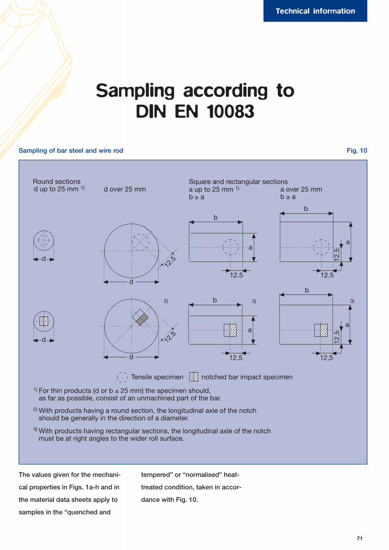
71
Sampling according to DIN EN 10083
Sampling of bar steel and wire rod Fig. 10
d up to 25 mm 1) d over 25 mm a up to 25 mm 1)
b ≥ aa over 25 mmb ≥ a
Round sections Square and rectangular sections
Tensile specimen notched bar impact specimen
For thin products (d or b ≤ 25 mm) the specimen should,as far as possible, consist of an unmachined part of the bar.
With products having a round section, the longitudinal axle of the notchshould be generally in the direction of a diameter.
With products having rectangular sections, the longitudinal axle of the notchmust be at right angles to the wider roll surface.
d
d
d
12.5
d
12.5
12.5
a
b
12.5
a
b
12.5
a
b
12.5
12,5
b
a
12.5
2) 3) 3)
1)
2)
3)
The values given for the mechani-
cal properties in Figs. 1a-h and in
the material data sheets apply to
samples in the “quenched and
tempered” or “normalised” heat-
treated condition, taken in accor-
dance with Fig. 10.
Technical information
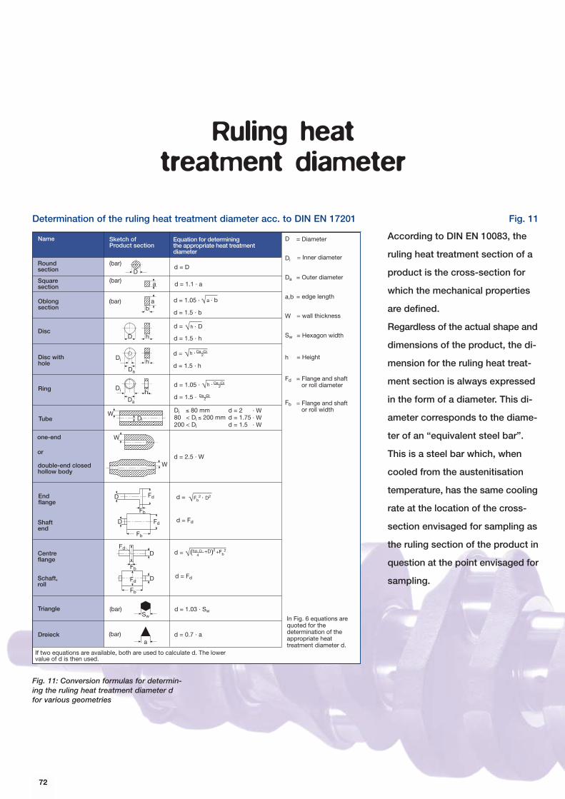
According to DIN EN 10083, the
ruling heat treatment section of a
product is the cross-section for
which the mechanical properties
are defined.
Regardless of the actual shape and
dimensions of the product, the di-
mension for the ruling heat treat-
ment section is always expressed
in the form of a diameter. This di-
ameter corresponds to the diame-
ter of an “equivalent steel bar”.
This is a steel bar which, when
cooled from the austenitisation
temperature, has the same cooling
rate at the location of the cross-
section envisaged for sampling as
the ruling section of the product in
question at the point envisaged for
sampling.
Determination of the ruling heat treatment diameter acc. to DIN EN 17201 Fig. 11
Fig. 11: Conversion formulas for determin-ing the ruling heat treatment diameter dfor various geometries
Ruling heat treatment diameter
d = D
d = 1.1 · a
Di ≤ 80 mm80 < Di ≤ 200 mm200 < Di
d = 2d = 1.75d = 1.5
d = 2.5 · W
d = Fd
d = Fd
d = 1.03 · Sw
d = 0.7 · a
a
ab
D h
Da
hDi
hDi
Da
DiW
W
W
FdD
D
Fb
Fd
Fb
FdD
Fb
Fb
Fd D
Sw
a
· W· W· W
D
D
Di
Da
a,b
W
Sw
h
Fd
Fb
Name
Roundsection
Squaresection
Oblongsection
Disc
Disc withhole
Ring
Tube
one-end
or
double-end closedhollow body
Endflange
Shaftend
Centreflange
Schaft,roll
Triangle
Dreieck
Sketch ofProduct section
Equation for determiningthe appropriate heat treatmentdiameter
(bar)
(bar)
(bar)
(bar)
(bar)
If two equations are available, both are used to calculate d. The lowervalue of d is then used.
In Fig. 6 equations arequoted for thedetermination of theappropriate heattreatment diameter d.
= Diameter
= Inner diameter
= Outer diameter
= edge length
= wall thickness
= Hexagon width
= Height
= Flange and shaft or roll diameter
= Flange and shaft or roll width
d = Fd- D4
+D( )2 +Fb2
d = Fb2 · D2
d = 1.5 · 2
Da -Di2h ·d = 1.05 ·
Da -Di
d =
d = 1.5 · h
Da -Di2h ·
d =
d = 1.5 · h
h · D
d = 1.05 ·
d = 1.5 · b
a · b
72
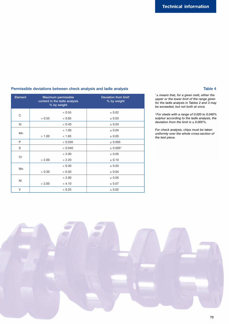
73
< 0.55 ± 0.02C
> 0.55 < 0.65 ± 0.03
Si < 0.40 ± 0.03
< 1.00 ± 0.04Mn
> 1.00 < 1.65 ± 0.05
P < 0.035 ± 0.005
S < 0.040 ± 0.0052
< 2.00 ± 0.05Cr
> 2.00 < 2.20 ± 0.10
< 0.30 ± 0.03Mo
> 0.30 < 0.50 ± 0.04
< 2.00 ± 0.05Ni
> 2.00 < 4.10 ± 0.07
V < 0.25 ± 0.02
1 ± means that, for a given melt, either theupper or the lower limit of the range givenfor the ladle analysis in Tables 2 and 3 maybe exceeded, but not both at once.
2 For steels with a range of 0.020 to 0.040%sulphur according to the ladle analysis, thedeviation from the limit is ± 0.005%.
For check analysis, chips must be takenuniformly over the whole cross-section ofthe test piece.
Maximum permissiblecontent in the ladle analysis
% by weight
Deviation from limit1
% by weight
Permissible deviations between check analysis and ladle analysis Table 4
Element
Technical information
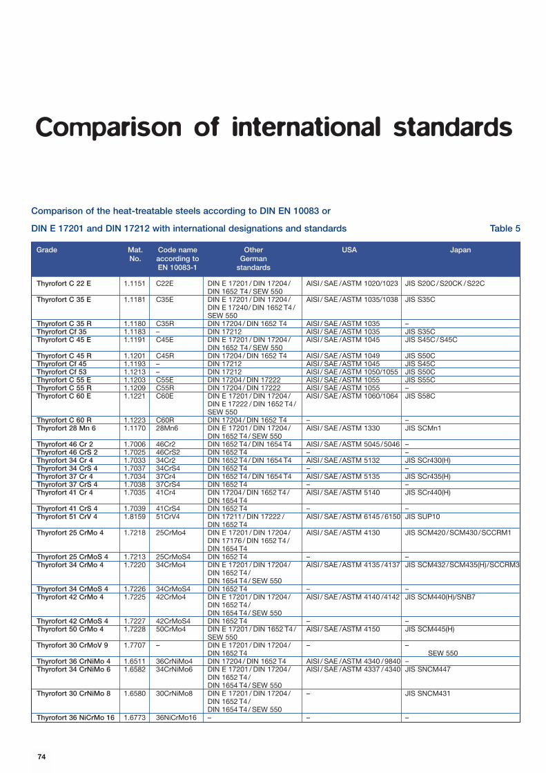
Grade Mat. Code name Other USA JapanNo. according to German
EN 10083-1 standards
Comparison of international standards
Comparison of the heat-treatable steels according to DIN EN 10083 or
DIN E 17201 and DIN 17212 with international designations and standards Table 5
Thyrofort C 22 E 1.1151 C22E DIN E 17201 / DIN 17204 / AISI / SAE /ASTM 1020/1023 JIS S20C/S20CK /S22CDIN 1652 T4 / SEW 550
Thyrofort C 35 E 1.1181 C35E DIN E 17201 / DIN 17204 / AISI / SAE /ASTM 1035/1038 JIS S35CDIN E 17240/ DIN 1652 T4 /SEW 550
Thyrofort C 35 R 1.1180 C35R DIN 17204 / DIN 1652 T4 AISI / SAE /ASTM 1035 –Thyrofort Cf 35 1.1183 – DIN 17212 AISI / SAE /ASTM 1035 JIS S35CThyrofort C 45 E 1.1191 C45E DIN E 17201 / DIN 17204 / AISI / SAE /ASTM 1045 JIS S45C/S45C
DIN 1652 T4 / SEW 550Thyrofort C 45 R 1.1201 C45R DIN 17204 / DIN 1652 T4 AISI / SAE /ASTM 1049 JIS S50CThyrofort Cf 45 1.1193 – DIN 17212 AISI / SAE /ASTM 1045 JIS S45CThyrofort Cf 53 1.1213 – DIN 17212 AISI / SAE /ASTM 1050/1055 JIS S50CThyrofort C 55 E 1.1203 C55E DIN 17204 / DIN 17222 AISI / SAE /ASTM 1055 JIS S55CThyrofort C 55 R 1.1209 C55R DIN 17204 / DIN 17222 AISI / SAE /ASTM 1055 –Thyrofort C 60 E 1.1221 C60E DIN E 17201 / DIN 17204 / AISI / SAE /ASTM 1060/1064 JIS S58C
DIN E 17222 / DIN 1652 T4 /SEW 550
Thyrofort C 60 R 1.1223 C60R DIN 17204 / DIN 1652 T4 – –Thyrofort 28 Mn 6 1.1170 28Mn6 DIN E 17201 / DIN 17204 / AISI / SAE /ASTM 1330 JIS SCMn1
DIN 1652 T4 / SEW 550Thyrofort 46 Cr 2 1.7006 46Cr2 DIN 1652 T4 / DIN 1654 T4 AISI / SAE /ASTM 5045/5046 –Thyrofort 46 CrS 2 1.7025 46CrS2 DIN 1652 T4 – –Thyrofort 34 Cr 4 1.7033 34Cr2 DIN 1652 T4 / DIN 1654 T4 AISI / SAE /ASTM 5132 JIS SCr430(H)Thyrofort 34 CrS 4 1.7037 34CrS4 DIN 1652 T4 – –Thyrofort 37 Cr 4 1.7034 37Cr4 DIN 1652 T4 / DIN 1654 T4 AISI / SAE /ASTM 5135 JIS SCr435(H)Thyrofort 37 CrS 4 1.7038 37CrS4 DIN 1652 T4 – –Thyrofort 41 Cr 4 1.7035 41Cr4 DIN 17204 / DIN 1652 T4 / AISI / SAE /ASTM 5140 JIS SCr440(H)
DIN 1654 T4Thyrofort 41 CrS 4 1.7039 41CrS4 DIN 1652 T4 – –Thyrofort 51 CrV 4 1.8159 51CrV4 DIN 17211 / DIN 17222 / AISI / SAE /ASTM 6145 /6150 JIS SUP10
DIN 1652 T4Thyrofort 25 CrMo 4 1.7218 25CrMo4 DIN E 17201 / DIN 17204 / AISI / SAE /ASTM 4130 JIS SCM420/SCM430/SCCRM1
DIN 17176 / DIN 1652 T4 /DIN 1654 T4
Thyrofort 25 CrMoS 4 1.7213 25CrMoS4 DIN 1652 T4 – –Thyrofort 34 CrMo 4 1.7220 34CrMo4 DIN E 17201 / DIN 17204 / AISI / SAE /ASTM 4135 /4137 JIS SCM432/SCM435(H)/SCCRM3
DIN 1652 T4 /DIN 1654 T4 / SEW 550
Thyrofort 34 CrMoS 4 1.7226 34CrMoS4 DIN 1652 T4 – –Thyrofort 42 CrMo 4 1.7225 42CrMo4 DIN E 17201 / DIN 17204 / AISI / SAE /ASTM 4140 /4142 JIS SCM440(H)/SNB7
DIN 1652 T4 /DIN 1654 T4 / SEW 550
Thyrofort 42 CrMoS 4 1.7227 42CrMoS4 DIN 1652 T4 – –Thyrofort 50 CrMo 4 1.7228 50CrMo4 DIN E 17201 / DIN 1652 T4 / AISI / SAE /ASTM 4150 JIS SCM445(H)
SEW 550Thyrofort 30 CrMoV 9 1.7707 – DIN E 17201 / DIN 17204 / – –
DIN 1652 T4 SEW 550Thyrofort 36 CrNiMo 4 1.6511 36CrNiMo4 DIN 17204 / DIN 1652 T4 AISI / SAE /ASTM 4340 /9840 –Thyrofort 34 CrNiMo 6 1.6582 34CrNiMo6 DIN E 17201 / DIN 17204 / AISI / SAE /ASTM 4337 /4340 JIS SNCM447
DIN 1652 T4 /DIN 1654 T4 / SEW 550
Thyrofort 30 CrNiMo 8 1.6580 30CrNiMo8 DIN E 17201 / DIN 17204 / – JIS SNCM431DIN 1652 T4 /DIN 1654 T4 / SEW 550
Thyrofort 36 NiCrMo 16 1.6773 36NiCrMo16 – – –
74
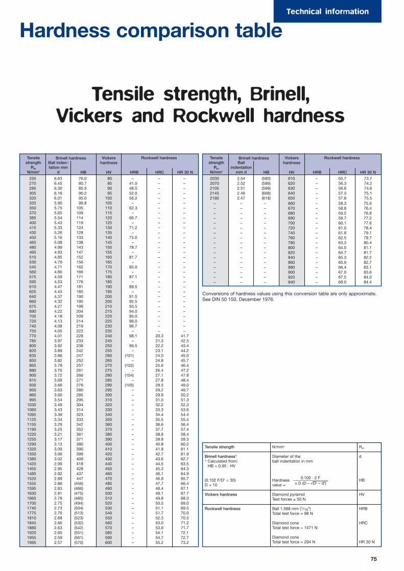
Technical information
75
Hardness comparison table
Tensile strength, Brinell, Vickers and Rockwell hardness
Tensilestrength
RmN/mm2
Ball inden-tation mm
d HB
Brinell hardness Vickershardness
HV
Rockwell hardness
HRB HRC HR 30 N
255 6.63 76.0 80 – – –270 6.45 80.7 85 41.0 – –285 6.30 85.5 90 48.0 – –305 6.16 90.2 95 52.0 – –320 6.01 95.0 100 56.2 – –335 5.90 99.8 105 – – –350 5.75 105 110 62.3 – –370 5.65 109 115 – – –385 5.54 114 120 66.7 – –400 5.43 119 125 – – –415 5.33 124 130 71.2 – –430 5.26 128 135 – – –450 5.16 133 140 75.0 – –465 5.08 138 145 – – –480 4.99 143 150 78.7 – –495 4.93 147 155 – – –510 4.85 152 160 81.7 – –530 4.79 156 165 – – –545 4.71 162 170 85.0 – –560 4.66 166 175 – – –575 4.59 171 180 87.1 – –595 4.53 176 185 – – –610 4.47 181 190 89.5 – –625 4.43 185 195 – – –640 4.37 190 200 91.5 – –660 4.32 195 205 92.5 – –675 4.27 199 210 93.5 – –690 4.22 204 215 94.0 – –705 4.18 209 220 95.0 – –720 4.13 214 225 96.0 – –740 4.08 219 230 96.7 – –755 4.05 223 235 – – –770 4.01 228 240 98.1 20.3 41.7785 3.97 233 245 – 21.3 42.5800 3.92 238 250 99.5 22.2 43.4820 3.89 242 255 – 23.1 44.2835 3.86 247 260 (101) 24.0 45.0850 3.82 252 265 – 24.8 45.7865 3.78 257 270 (102) 25.6 46.4880 3.75 261 275 – 26.4 47.2900 3.72 266 280 (104) 27.1 47.8915 3.69 271 285 – 27.8 48.4930 3.66 276 290 (105) 28.5 49.0950 3.63 280 295 – 29.2 49.7965 3.60 285 300 – 29.8 50.2995 3.54 295 310 – 31.0 51.3
1030 3.49 304 320 – 32.2 52.31060 3.43 314 330 – 33.3 53.61095 3.39 323 340 – 34.4 54.41125 3.34 333 350 – 35.5 55.41155 3.29 342 360 – 36.6 56.41190 3.25 352 370 – 37.7 57.41220 3.21 361 380 – 38.8 58.41255 3.17 371 390 – 39.8 59.31290 3.13 380 400 – 40.8 60.21320 3.09 390 410 – 41.8 61.11350 3.06 399 420 – 42.7 61.91385 3.02 409 430 – 43.6 62.71420 2.99 418 440 – 44.5 63.51455 2.95 428 450 – 45.3 64.31485 2.92 437 460 – 46.1 64.91520 2.89 447 470 – 46.9 65.71555 2.86 (456) 480 – 47.7 66.41595 2.83 (466) 490 – 48.4 67.11630 2.81 (475) 500 – 49.1 67.71665 2.78 (485) 510 – 49.8 68.31700 2.75 (494) 520 – 50.5 69.01740 2.73 (504) 530 – 51.1 69.51775 2.70 (513) 540 – 51.7 70.01810 2.68 (523) 550 – 52.3 70.51845 2.66 (532) 560 – 53.0 71.21880 2.63 (542) 570 – 53.6 71.71920 2.60 (551) 580 – 54.1 72.11955 2.59 (561) 590 – 54.7 72.71995 2.57 (570) 600 – 55.2 73.2
Tensilestrength
RmN/mm2
Ballindentation
mm d HB
Brinell hardness Vickershardness
HV
Rockwell hardness
HRB HRC HR 30 N
2030 2.54 (580) 610 – 55.7 73.72070 2.52 (589) 620 – 56.3 74.22105 2.51 (599) 630 – 56.8 74.62145 2.49 (608) 640 – 57.3 75.12180 2.47 (618) 650 – 57.8 75.5
– – – 660 – 58.3 75.9– – – 670 – 58.8 76.4– – – 680 – 59.2 76.8– – – 690 – 59.7 77.2– – – 700 – 60.1 77.6– – – 720 – 61.0 78.4– – – 740 – 61.8 79.1– – – 760 – 62.5 79.7– – – 780 – 63.3 80.4– – – 800 – 64.0 81.1– – – 820 – 64.7 81.7– – – 840 – 65.3 82.2– – – 860 – 65.9 82.7– – – 880 – 66.4 83.1– – – 900 – 67.0 83.6– – – 920 – 67.5 84.0– – – 940 – 68.0 84.4
Tensile strength N/mm2 Rm
Brinell hardness1) Diameter of the d1) Calculated from: ball indentation in mm
HB = 0.95 · HV
(0.102 F/D2 = 30) Hardness HBD = 10 value =
Vickers hardness Diamond pyramid HVTest forces ≥ 50 N
Rockwell hardness Ball 1.588 mm (1/16“) HRBTotal test force = 98 N
Diamond cone HRCTotal test force = 1471 N
Diamond coneTotal test force = 294 N HR 30 N
0.102 · 2 Fπ D (D – √D2 – d2)
Conversions of hardness values using this conversion table are only approximate.See DIN 50 150, December 1976.

76
Forms supplied
55 – 250 mm dia.
Sharp-edged50 – 103 mm square
DIN 1014
DIN 7527
DIN 1013
> 200 mm dia. standard in-company tolerance, closertolerance on request
Subject topurchaseorder
Special:*)≤ +100/-0
Flat:Width: 80 – 510 mmThickness: 25 – 160 mmWidth/thickness ratio 10:1 max
Width: 25 – 160 mm
Thickness:80 – 550 mm
65 – 750 mm dia.
265 – 650 mm square
flat: on request
50 – 320 mm square,rising in 1 mm incre-ments
52 – 400 mm dia.
52 – 300 mm dia.
DIN 1017up to 150 mm width and 60 mm thickness;over 150 mm widthstandard in-company tole-rance
Tolerance on request
< 210 mm +/- 2%> 210 mm +/- 3%of edge length
Special:*)≤ 100 mm +/- 1%
of edge length
> 100 mm – 210 mm
+/- 1.5% of edge length
ISA Tol. 11 or comparabletolerance
ISA Tol. 11 or comparabletolerance
ISA-Tol. 8 or comparable tolerance
≤ 80 mm: 4.0 mm/m
> 80 mm: 2.5 mm/m
4.0 – 10 m,other lengthson request
Lengths as a function ofdimensionsand heat-treatmentcondition on request
3 - 10 m, onrequest 30 mmax. as afunction ofdia. andmax. bardead weightof 7 t
Hot-sawn or hot abrasi-ve-cut
Special:*)Cold-sawn,cold abrasive-cut
Hot abrasive-cut or cold-sawn
Special:*)Cold abrasive-cut
≤ 210 mm square:hot-sawn or hot abrasi-ve-cut
> 210 mm square:hot-sheared
Special:*)Cold abrasive-cut, cold-sawn
Hot-sawn/hotabrasive-cut
Special:*)Cold-sawn/abrasive-cut
Dimensions 50- 105 mm withround chamfer30° or 45°,chamfer widthapprox. 5 -12mm, otherwidths by ar-rangement
Rough-peeled finishavailable for 52 -240 mm
Max. permissiblesurface defect dep-ths:
Round: 1% max. ofdia. + 0.05 mm
Square: 1% max. ofedge length
Flat: 1.5% max. ofwidth, 2.0% max. ofthickness
Special:*)Smaller surfacedefect depth onrequest
Special:*)
- Rough-peeled- Turned- Milled
Edge radius:
< 210 mm - 12-18%of edge length
> 210 mm: withoutdefined edge radius
Max. perm. surfacedefect depth:
≤ 140 mm sq.0.3 mm max.
> 140 - 200 mm sq.0.6 mm max.
> 200 mm sq.visible defects elimi-nated
Technically crack-freecondition e.g. eddy-current tested orcomparable tech-nique, defined depthof roughness and sui-table packaging byspecial arrangement
< 1000 mm2:4.0 mm/m
> 1000 mm2:2.5 mm/m
Special:*)Speciallystraightened
Standard: 6 mm/m
Special:*)4 mm/m
As-peeledstraightness ≤ 2 mm/m, 1 mm/m orcloser as afunction ofdimensions on request
Untreated
Cold-sheara-ble
Cold-sawable
Normalized
Treated toferrite-pearlitestructure
Treated tohardnessrange
Soft-annealed
Spheroidize-annealed
Stress-relie-ved
Quenchedand tempered
Bar steeland roundbillets fortubemakingrolled
Sheet barsrolled withbulbous nar-row face
Bar steeland semis forged
Semisrolled
Bright steel
peeled
peeled andpolished
*) Special finishes subject to further inquiry (partly dependent on quality, dimensions and condition)
ground 52 – 100 mm dia.
Semis:as-forgedstraightness
Bar steel:to DIN withinthe tolerancelimit
3 – 8 m
Surface finishAs-suppliedcondition
End condition
Lengths/weightsStraightnessLengthsDia. or edge length
TolerancesProduct Dimensions
on requestAs-castingots/c.c.blooms Open-dieforgings
Forgings forged toshape on request(drawing)
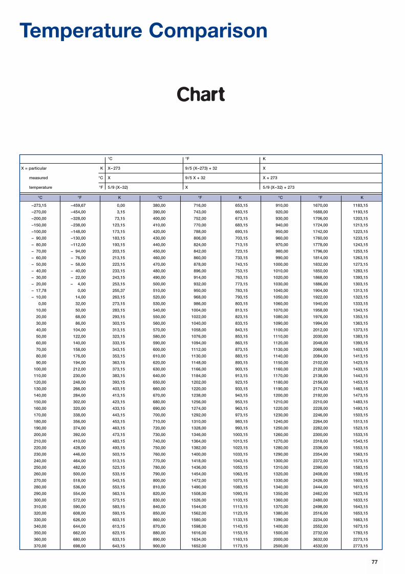
Temperature Comparison
Chart
°C °F K °C °F K °C °F K
–273,15 –459,67 0,00 380,00 716,00 653,15 910,00 1670,00 1183,15
–270,00 –454,00 3,15 390,00 743,00 663,15 920,00 1688,00 1193,15
–200,00 –328,00 73,15 400,00 752,00 673,15 930,00 1706,00 1203,15
–150,00 –238,00 123,15 410,00 770,00 683,15 940,00 1724,00 1213,15
–100,00 –148,00 173,15 420,00 788,00 693,15 950,00 1742,00 1223,15
– 90,00 –130,00 183,15 430,00 806,00 703,15 960,00 1760,00 1233,15
– 80,00 –112,00 193,15 440,00 824,00 713,15 970,00 1778,00 1243,15
– 70,00 – 94,00 203,15 450,00 842,00 723,15 980,00 1796,00 1253,15
– 60,00 – 76,00 213,15 460,00 860,00 733,15 990,00 1814,00 1263,15
– 50,00 – 58,00 223,15 470,00 878,00 743,15 1000,00 1832,00 1273,15
– 40,00 – 40,00 233,15 480,00 896,00 753,15 1010,00 1850,00 1283,15
– 30,00 – 22,00 243,15 490,00 914,00 763,15 1020,00 1868,00 1393,15
– 20,00 – 4,00 253,15 500,00 932,00 773,15 1030,00 1886,00 1303,15
– 17,78 0,00 255,37 510,00 950,00 783,15 1040,00 1904,00 1313,15
– 10,00 14,00 263,15 520,00 968,00 793,15 1050,00 1922,00 1323,15
0,00 32,00 273,15 530,00 986,00 803,15 1060,00 1940,00 1333,15
10,00 50,00 283,15 540,00 1004,00 813,15 1070,00 1958,00 1343,15
20,00 68,00 293,15 550,00 1022,00 823,15 1080,00 1976,00 1353,15
30,00 86,00 303,15 560,00 1040,00 833,15 1090,00 1994,00 1363,15
40,00 104,00 313,15 570,00 1058,00 843,15 1100,00 2012,00 1373,15
50,00 122,00 323,15 580,00 1076,00 853,15 1110,00 2030,00 1383,15
60,00 140,00 333,15 590,00 1094,00 863,15 1120,00 2048,00 1393,15
70,00 158,00 343,15 600,00 1112,00 873,15 1130,00 2066,00 1403,15
80,00 176,00 353,15 610,00 1130,00 883,15 1140,00 2084,00 1413,15
90,00 194,00 363,15 620,00 1148,00 893,15 1150,00 2102,00 1423,15
100,00 212,00 373,15 630,00 1166,00 903,15 1160,00 2120,00 1433,15
110,00 230,00 383,15 640,00 1184,00 913,15 1170,00 2138,00 1443,15
120,00 248,00 393,15 650,00 1202,00 923,15 1180,00 2156,00 1453,15
130,00 266,00 403,15 660,00 1220,00 933,15 1190,00 2174,00 1463,15
140,00 284,00 413,15 670,00 1238,00 943,15 1200,00 2192,00 1473,15
150,00 302,00 423,15 680,00 1256,00 953,15 1210,00 2210,00 1483,15
160,00 320,00 433,15 690,00 1274,00 963,15 1220,00 2228,00 1493,15
170,00 338,00 443,15 700,00 1292,00 973,15 1230,00 2246,00 1503,15
180,00 356,00 453,15 710,00 1310,00 983,15 1240,00 2264,00 1513,15
190,00 374,00 463,15 720,00 1328,00 993,15 1250,00 2282,00 1523,15
200,00 392,00 473,15 730,00 1346,00 1003,15 1260,00 2300,00 1533,15
210,00 410,00 483,15 740,00 1364,00 1013,15 1270,00 2318,00 1543,15
220,00 428,00 493,15 750,00 1382,00 1023,15 1280,00 2336,00 1553,15
230,00 446,00 503,15 760,00 1400,00 1033,15 1290,00 2354,00 1563,15
240,00 464,00 513,15 770,00 1418,00 1043,15 1300,00 2372,00 1573,15
250,00 482,00 523,15 780,00 1436,00 1053,15 1310,00 2390,00 1583,15
260,00 500,00 533,15 790,00 1454,00 1063,15 1320,00 2408,00 1593,15
270,00 518,00 543,15 800,00 1472,00 1073,15 1330,00 2426,00 1603,15
280,00 536,00 553,15 810,00 1490,00 1083,15 1340,00 2444,00 1613,15
290,00 554,00 563,15 820,00 1508,00 1093,15 1350,00 2462,00 1623,15
300,00 572,00 573,15 830,00 1526,00 1103,15 1360,00 2480,00 1633,15
310,00 590,00 583,15 840,00 1544,00 1113,15 1370,00 2498,00 1643,15
320,00 608,00 593,15 850,00 1562,00 1123,15 1380,00 2516,00 1653,15
330,00 626,00 603,15 860,00 1580,00 1133,15 1390,00 2234,00 1663,15
340,00 644,00 613,15 870,00 1598,00 1143,15 1400,00 2552,00 1673,15
350,00 662,00 623,15 880,00 1616,00 1153,15 1500,00 2732,00 1783,15
360,00 680,00 633,15 890,00 1634,00 1163,15 2000,00 3632,00 2273,15
370,00 698,00 643,15 900,00 1652,00 1173,15 2500,00 4532,00 2773,15
°C °F K
X = particular K X– 273 9/5 (X–273) + 32 X
measured °C X 9/5 X + 32 X + 273
temperature °F 5/9 (X–32) X 5/9 (X–32) + 273
77
78
Page Source Object/Motif
Cover Alfing Crankshaft03 Steinmetz Crankshaft04 MAN, B&W Ship’s engine4 – 5 Company photo Forge4 – 5 Company photo, Siemens Turbine shaft5 Company photo Team meeting6 Thyssen Umformtechnik Crankshaft6 – 7 Alfing Crankshaft7 Steinmetz Chips8 Company photo Bar steel warehouse8 Company photo Bar steel warehouse8 – 9 Steinmetz Rudder spindles9 Company photo Bar steel warehouse
10 Bavaria Landing gear10 Imagine Oil tanker10 – 11 MAN Ship’s engine10 – 11 Shuton Recirculating ball screw10 PSA Peugot Citroen Peugot 60711 DAF XF95 truck11 Doppelmayr Chairlift11 Mannesmann High-pressure tubes11 Company photo Sliding sleeve11 Image Ariane launcher
12 Company photo Wheel loader12 Atlas Copco Demolition hammer12 – 13 Mannesmann Röhrenwerke Continuous tube mill12 Company photo Sliding sleeve13 Baker Hughes Oil tool13 Company photo Drilling rig13 Schwellis/Peddinghaus BMW suspension13 Schwellis/Peddinghaus Ripper tips/Excavator tooth13 Company photo Axle stub13 Worthington Heiser Gas cylinders14 Company photo Electric arc furnace14 Company photo Vacuum plant15 Company photo Continuous casting plant15 Company photo ESR plant16 Company photo Control room, 3000 t press16 Company photo Forging bar steel16 Company photo Blooming mill16 – 17 Company photo Forging, 3000 t press17 Carlow Peeling machine17 Company photo Bar steel warehouse17 Company photo Forging, 3000 t press
List of photos

79
General note (liability)
All statements regarding the properties
or utilisation of the materials or products
mentioned are for the purposes of
description only. Guarantees regarding
the existence of certain properties or a
certain utilisation are only ever valid if
agreed upon in writing.
THYROFORTTHYROFORT
THYROFORT
EDELSTAHL WITTEN-KREFELD GMBHAuestraße 4, 58452 Witten/Germany · Tel. (+49) 2302/294307 · Fax (+49) 2302/294308
E-mail: [email protected] · Internet: www.edelstahl-witten-krefeld.de
• Sales - Heat-treatable steelsTel. (+49) 2302/294346 · Fax (+49) 2302/294687 0 23 0E-mail: [email protected]
• Quality DepartmentTel. (+49) 2302/294020 · Fax (+49) 2302/2944363 02/29 44 36Tel. (+49) 2151/832046 · Fax (+49) 2151/834156
c1/0
0
Heat-treatable steels
THYROFORTTHYROFORT
THYROFORT


