Download - Schiebe-Kipp / PVC / Zwangssteuerung - MACO
SKB-Z
TECHNIK DIE BEWEGT
AnschlAgAnleitung
schieBeBeschlÄge
Schiebe-Kipp / PVC / Zwangssteuerung
TECHNOLOGY IN MOTION
instAllAtiOn instRuctiOn
sliDing Fittings
Tilt&Slide fittings / PVC / Positive control
LA TECHNOLOGIE QUI ÉVOLUE
instRuctiOns De MOntAge
FeRRuRes De cOulissAnts
Coulissant à translation / PVC / Manœuvre forcée
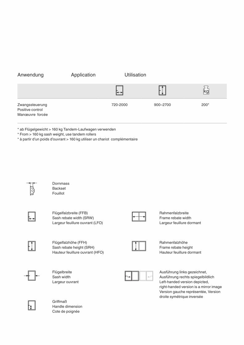
720-2000 900–2700 200*
Griffmaß
Ausführung links gezeichnet, Ausführung rechts spiegelbildlich
Flügelfalzbreite (FFB)
Dornmass
Flügelfalzhöhe (FFH)
Flügelbreite
Rahmenfalzbreite
Rahmenfalzhöhe
Anwendung
Zwangssteuerung
* ab Flügelgewicht > 160 kg Tandem-Laufwagen verwenden
Handle dimension
Left-handed version depicted, right-handed version is a mirror image
Sash rebate width (SRW)
Backset
Sash rebate height (SRH)
Sash width
Frame rebate width
Frame rebate height
Application
Positive control
* From > 160 kg sash weight, use tandem rollers
Cote de poignée
Version gauche représentée, Version droite symétrique inversée
Largeur feuillure ouvrant (LFO)
Fouillot
Hauteur feuillure ouvrant (HFO)
Largeur ouvrant
Largeur feuillure dormant
Hauteur feuillure dormant
Utilisation
Manœuvre forcée
* à partir d’un poids d’ouvrant > 160 kg utiliser un chariot complémentaire
Überblick (Seiten zum Ausklappen)
Produkthaftung 2
Konstruktion 6
Anschlaganleitung 11
Einbau Flügel 30
Einstellung und Regulierung 32
Explosionszeichnung und Teileliste
Schnitte Maßstab 1:1
Inhalt
Overview (folded pages)
Product liability
Design
Installation instructions
Sash installation
Adjustments
Exploded drawing and parts list
Profile cross section scale 1:1
Contents
Aperçu (pages rabattables)
Responsabilité produit
Construction
Instructions de montage
Pose de l’ouvrant
Réglage et régulation
Plan éclaté et liste des pièces
Coupes échelle 1:1
Contenu
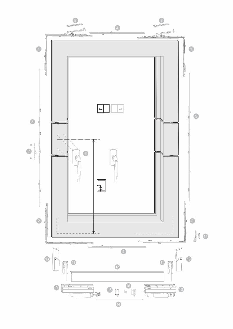
Ausklappseite 1: Explosionszeichnung, Griffbohrung und Teileliste
Folded page 1: Exploded drawing, handle drilling, and parts list
Page rabattable 1:
Plan éclaté, perçage de poignée et liste des pièces
131
∅ 3∅ 74x
199 218F
X
0124
A
B
133
C
D
124
E
x
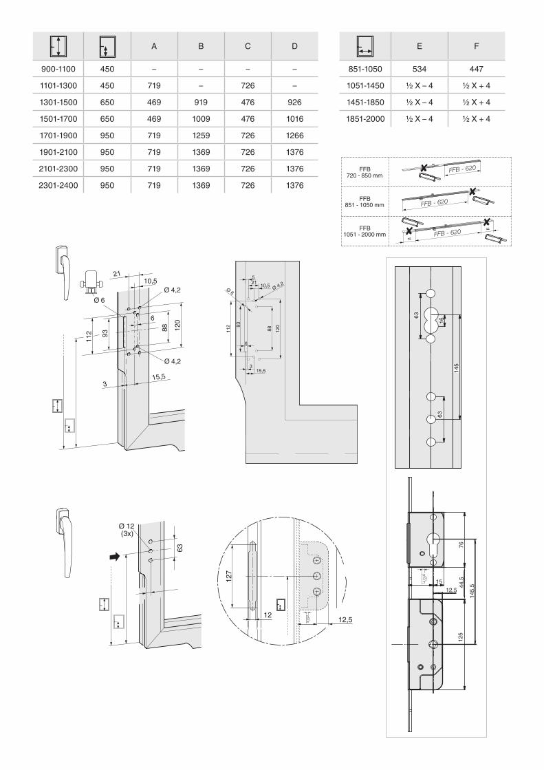
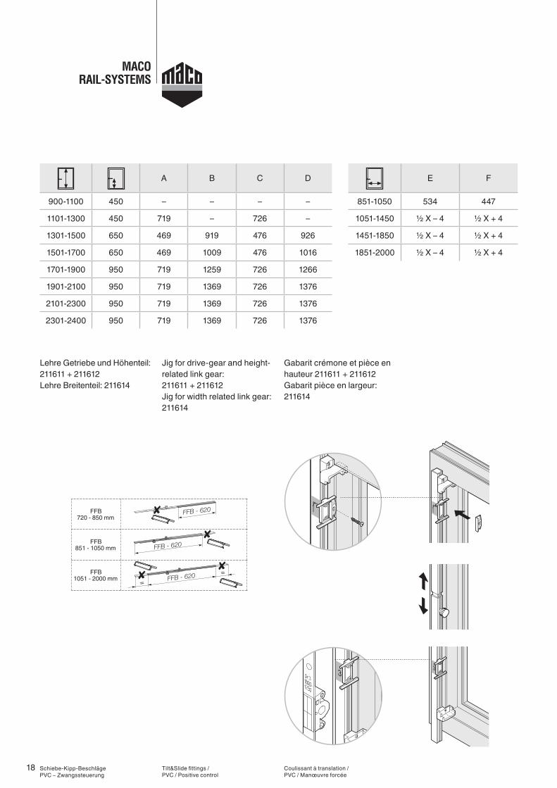
A B C D
900-1100 450 – – – –
1101-1300 450 719 – 726 –
1301-1500 650 469 919 476 926
1501-1700 650 469 1009 476 1016
1701-1900 950 719 1259 726 1266
1901-2100 950 719 1369 726 1376
2101-2300 950 719 1369 726 1376
2301-2400 950 719 1369 726 1376
E F
851-1050 534 447
1051-1450 ½ X – 4 ½ X + 4
1451-1850 ½ X – 4 ½ X + 4
1851-2000 ½ X – 4 ½ X + 4
315,5
93
120
88
112
10,5
6
Ø 4,2
Ø 4,2Ø 6
21
Ø 12(3x)
63
127
12
∅ 4,2521 10,5
88 12093
112
3
∅ 6
15,5
6
12,5
1512,5
7644
,512
5
145,
5
1663
145
63
==
FFB720 - 850 mm
FFB851 - 1050 mm
FFB1051 - 2000 mm
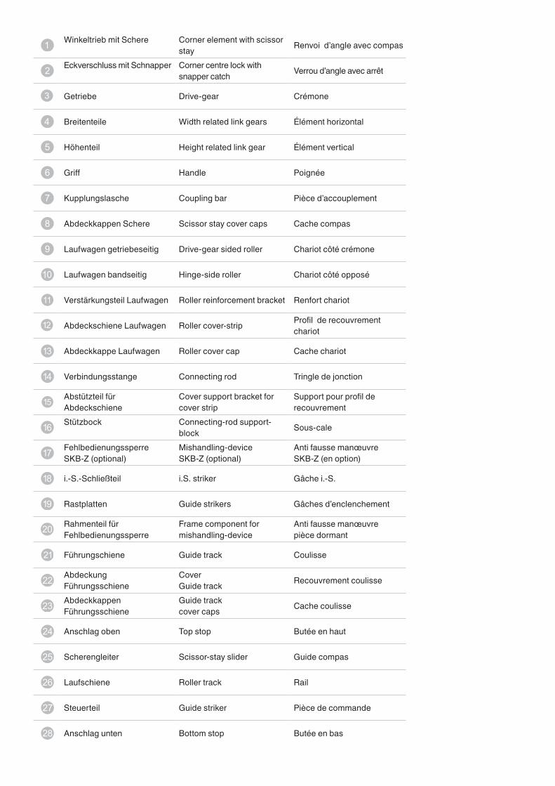
Winkeltrieb mit Schere
Eckverschluss mit Schnapper
Getriebe
Breitenteile
Höhenteil
Griff
Kupplungslasche
Abdeckkappen Schere
Laufwagen getriebeseitig
Laufwagen bandseitig
Verstärkungsteil Laufwagen
Abdeckschiene Laufwagen
Abdeckkappe Laufwagen
Verbindungsstange
Abstützteil für AbdeckschieneStützbock
Fehlbedienungssperre SKB-Z (optional)
i.-S.-Schließteil
Rastplatten
Rahmenteil für Fehlbedienungssperre
Führungschiene
Abdeckung FührungsschieneAbdeckkappen Führungsschiene
Anschlag oben
Scherengleiter
Laufschiene
Steuerteil
Anschlag unten
Corner element with scissor stayCorner centre lock with snapper catch
Drive-gear
Width related link gears
Height related link gear
Handle
Coupling bar
Scissor stay cover caps
Drive-gear sided roller
Hinge-side roller
Roller reinforcement bracket
Roller cover-strip
Roller cover cap
Connecting rod
Cover support bracket for cover stripConnecting-rod support-blockMishandling-device SKB-Z (optional)
i.S. striker
Guide strikers
Frame component for mishandling-device
Guide track
Cover Guide trackGuide track cover caps
Top stop
Scissor-stay slider
Roller track
Guide striker
Bottom stop
Renvoi d’angle avec compas
Verrou d’angle avec arrêt
Crémone
Élément horizontal
Élément vertical
Poignée
Pièce d’accouplement
Cache compas
Chariot côté crémone
Chariot côté opposé
Renfort chariot
Profil de recouvrement chariot
Cache chariot
Tringle de jonction
Support pour profil de recouvrement
Sous-cale
Anti fausse manœuvre SKB-Z (en option)
Gâche i.-S.
Gâches d’enclenchement
Anti fausse manœuvre pièce dormant
Coulisse
Recouvrement coulisse
Cache coulisse
Butée en haut
Guide compas
Rail
Pièce de commande
Butée en bas
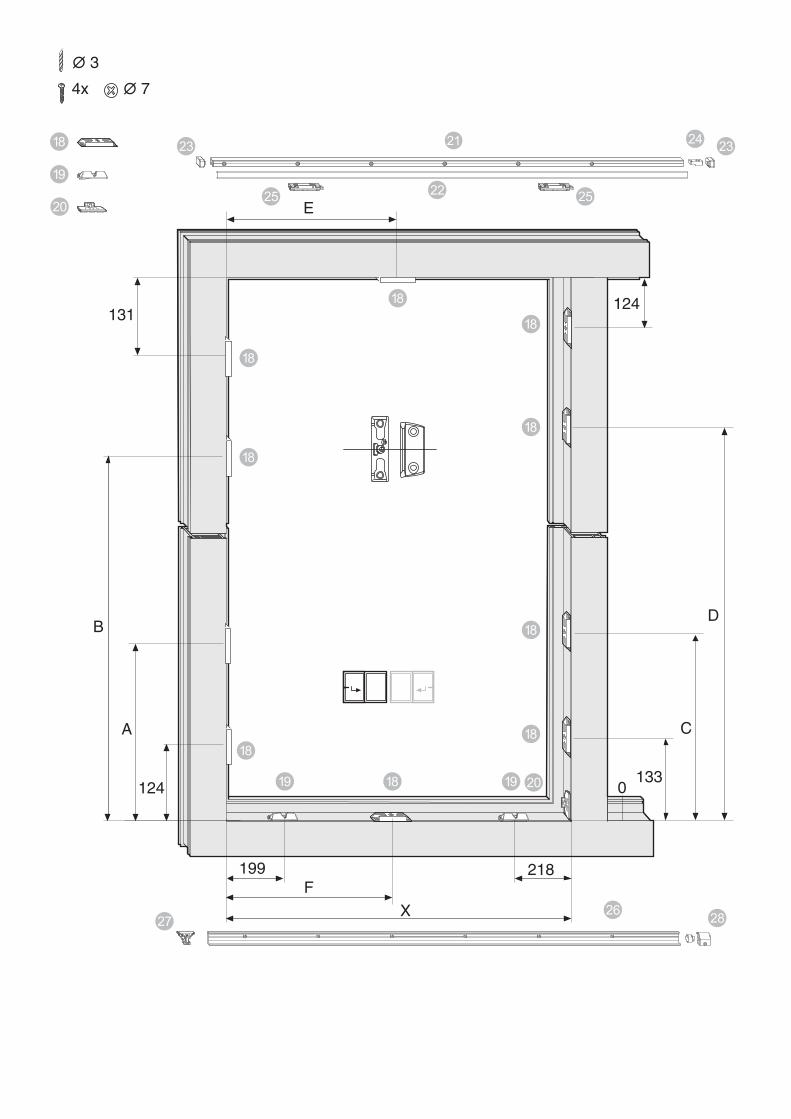
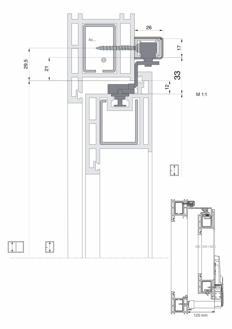
Ausklappseite 2:
Schnitte (M 1:1), Ansicht Flügel und Rahmen
Folded page 2:
Profile cross sections (M 1:1), sash and frame elevation
Page rabattable 2:
Coupes (Ech.1), Vue ouvrant et dormant
4x...
26
1733
29,5
21
12
125 mm
M 1:1
4x...
23
2012
5x...
35
412
max.
12
M 1:1
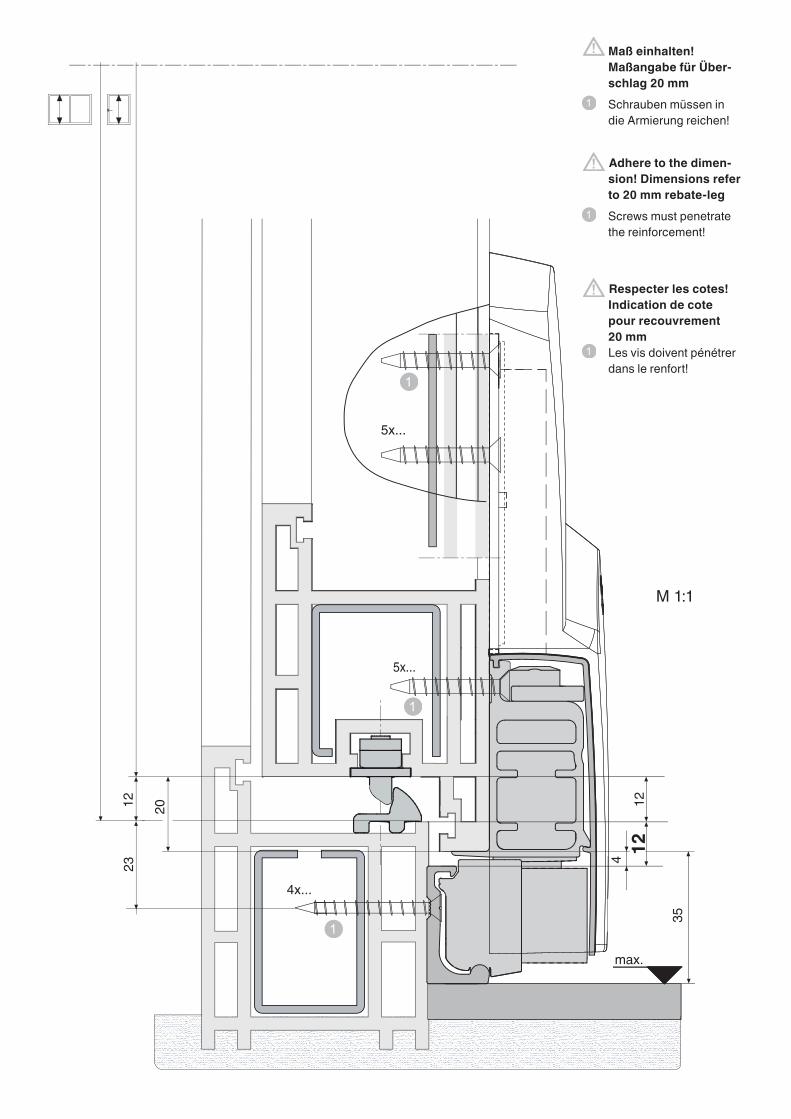
Maß einhalten! Maßangabe für Über-
schlag 20 mm Schrauben müssen in
die Armierung reichen!
Adhere to the dimen- sion! Dimensions refer to 20 mm rebate-leg
Screws must penetrate the reinforcement!
Respecter les cotes! Indication de cote pour recouvrement
20 mm Les vis doivent pénétrer
dans le renfort!
10 10
10 10
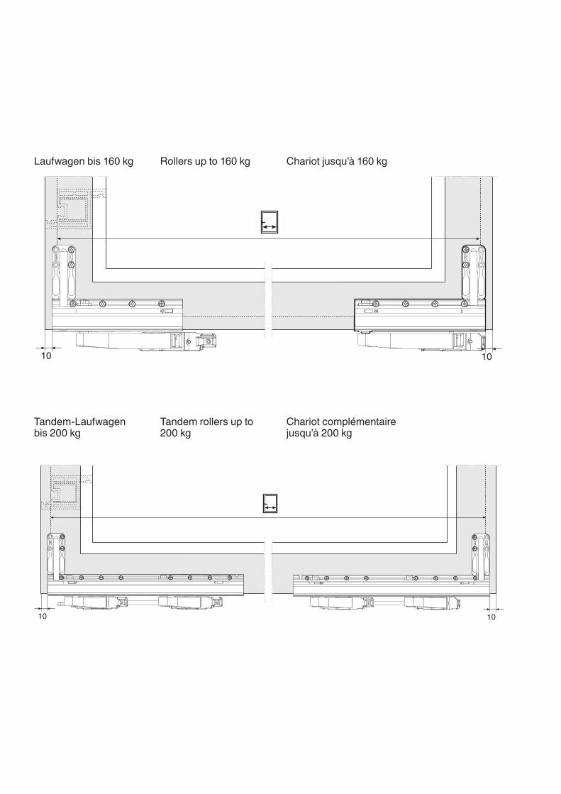
Laufwagen bis 160 kg
Tandem-Laufwagen bis 200 kg
Rollers up to 160 kg
Tandem rollers up to 200 kg
Chariot jusqu’à 160 kg
Chariot complémentaire jusqu’à 200 kg
2 Schiebe-Kipp-Beschläge PVC – Zwangssteuerung
Produkthaftung Wichtige Hinweise
• Beachten Sie die Höchst- und Mindestmaße, sowie das max. zulässige Flügelgewicht.
• Beachten Sie die Angaben der Profilhersteller, insbesonde-re zu möglichen Einschränkungen der Höchst- und Mindest-maße, des Flügelgewichts und des Verriegelungsabstands.
• Nehmen Sie keine konstruktiven Veränderungen an den Beschlagsteilen vor.
• Verwenden Sie ausschließlich MACO-Beschläge für den Gesamtbeschlag.
• Montieren Sie die Beschlagteile entsprechend dieser Anlei-tung und beachten Sie alle Sicherheitshinweise.
• Verwenden Sie die angegebenen Schraubengrößen. Stim-men Sie die Längen der Schrauben auf das verwendete Profilsystem ab.
• Drehen Sie die Schrauben gerade (wenn nicht anders ange-geben) und nicht zu fest ein, da sonst die Leichtgängigkeit des Beschlags beeinträchtigt wird.
• Befestigen Sie die Schrauben der tragenden Bauteile (z. B. Laufwagen, Lauf- und Führungsschiene) im Aussteifungs-profil.
• Achten Sie im Bereich der Laufwagen auf eine formschlüs-sige Übertragung der Druckkräfte auf das Aussteifungs- profil.
• Verwenden Sie keine säurevernetzenden Dichtstoffe, da diese zur Korrosion der Beschlagsteile führen können.
• Halten Sie die Laufschiene und alle Falze von Verschmut-zungen und Putzrückständen frei. Vermeiden Sie den Kontakt des Beschlags mit Nässe und Reinigungsmitteln.
• Bringen Sie den Bedienungsaufkleber gut sichtbar am ein-gebauten Schiebekipp-Flügel an.
• Durch Überbeanspruchung oder nicht sachgemäße Be-dienung des Schiebekipp-Beschlags kann der Flügel aus seiner Führung springen, herausfallen und dadurch schwe-re Verletzungen verursachen. Wenn unter besonderen Um-ständen (Einsatz in Schulen, Kindergärten etc.) zu erwarten ist, dass das Schiebekipp-Element überbeansprucht wird, muss dies durch geeignete Maßnahmen verhindert werden. Z. B.
– Versetzen des Anschlagbocks zur Verringerung der Öffnungsweite, oder
– Einbau eines Profilzylinders gegen unbefugte Benutzung.
Nehmen Sie in Zweifelsfällen Rücksprache mit Ihrem An-sprechpartner bei MACO.
Haftungsausschluss
Wir haften nicht für Funktionsstörungen und Beschädigungen der Beschläge sowie der damit ausgestatteten Schiebekipp-Elemente, die auf unzureichende Ausschreibung, Nichtbeach-tung dieser Anschlaganleitung oder Gewalteinwirkung auf den Beschlag (z. B. durch nicht bestimmungsgemäßen Gebrauch) zurückzuführen sind.
Tilt&Slide fittings / PVC / Positive control
Coulissant à translation / PVC / Manœuvre forcée
3Schiebe-Kipp-Beschläge PVC – Zwangssteuerung
Tilt&Slide fittings / PVC / Positive control
Product liability Important advice
• Please note the maximum and minimum dimensions, as well as the max. permissible sash weight.
• Please note the profile manufacturer’s specifications, in particular possible restrictions concerning the maximum and minimum dimensions, the sash weight, and the locking-point distance.
• Please do not carry out any constructive changes on the fittings components.
• Please use exclusively MACO fittings for the entire set of fittings.
• Install the fittings components in accordance with these instructions and note all of the safety instructions.
• Use the specified screw sizes. Match the screw lengths with the profile system being used.
• Drive the screws in straight (if not stated otherwise) and not too tight, as it otherwise impairs the fitting’s smooth operati-on.
• Screw-fix the supporting components’ screws (e.g. rollers, bottom roller-track, and top guide-track) in the reinforce-ment profile.
• Note the positive-fitting transfer of pressure forces on the reinforcement profile in the vicinity of the roller.
• Use no cross-linked acidic sealing compounds, as these can lead to corrosion of the fittings components.
• Keep the roller track and all rebates free from dirt and plas-ter residue. Avoid having the fittings in contact with wetness and cleaning agents.
• Apply the operation sticker clearly visible on the fitted Tilt&Slide sash.
• If the Tilt&Slide fittings are overused or not properly opera-ted, the sash can jump out of its guides, fall out, and as a result cause severe injuries. If in special circumstances it is expected, that the Tilt&Slide unit will be overused (school or kindergarden applications etc), suitable measures must carried out to prevent this. E.g.:
– Moving the stop to reduce the opening width, or – installing a profile cylinder to prevent unauthorised use. If in doubt please contact your MACO contact person.
Liability exclusion
We are not liable for malfunctions and damage to the fittings, as well as to the Tilt&Slide units equipped with the same, if this has been caused by inadequate tendering procedures, non-compliance with these installation instructions, or phy-sical effect of force on the fittings (e.g. due to non specified use).
Coulissant à translation / PVC / Manœuvre forcée
4 Schiebe-Kipp-Beschläge PVC – Zwangssteuerung
Tilt&Slide fittings / PVC / Positive control
Coulissant à translation / PVC / Manœuvre forcée
Responsabilité produit Consignes importantes
• Veuillez tenir compte des cotes maximales et minimales ainsi que du poids d’ouvrant maximal autorisé.
• Veuillez tenir compte des indications du fabricant de profilés, en particulier en ce qui concerne les restrictions possibles des cotes maximales et minimales, du poids de l’ouvrant et de l’entraxe de verrouillage.
• N’entreprenez aucune modification de la construction des pièces de ferrure.
• Utilisez exclusivement des ferrures MACO pour l’ensemble de la ferrure.
• Veuillez monter les pièces de ferrure selon la présente noti-ce et respecter toutes les consignes de sécurité.
• Veuillez utiliser les dimensions de vis appropriées. Accor-dez les longueurs de vis avec le système de profil utilisé.
• Tournez les vis dans le sens droite (sauf indication con-traire) et sans excès, afin de ne pas influencer le bon foncti-onnement de la ferrure.
• Fixez les vis des éléments porteurs de la construction (par ex. chariot, rail et coulisse) dans le profilé de renfort.
• Veillez, dans la zone du chariot, à une transmission méca-nique des pressions induites, sur le profilé de renfort.
• N’utilisez pas de produits traités à l’ acide, ceux-ci pouvant provoquer la corrosion des pièces de ferrures.
• Le rail et toutes les feuillures doivent être conservés ex-empts de salissures et de résidus de nettoyage. Evitez le contact du ferrage avec l’eau et les produits de nettoyage.
• Apposez de façon bien visible l’étiquette d’utilisation sur l’ouvrant coulissant à translation une fois posé.
• En cas de violation ou de commande non conforme de la ferrure coulissante à translation, l’ouvrant peut se déboiter de son rail, tomber et causer ainsi des blessures graves. Si dans des circonstances spéciales (mise en œuvre dans des écoles, jardins d’enfants etc.) il faut s’attendre à ce que l’élément coulissant à translation soit forcé, il faut éviter cela par des mesures appropriées. Par ex.
– Déplacement de la butée afin de réduire la largeur d’ouverture, ou
– mise en place d’un barillet profilé empêchant une utili- sation non autorisée.
En cas de doute, consultez votre interlocuteur chez MACO.
Exclusion de responsabilité
Nous déclinons toute responsabilité pour les désordres de fonctionnement et les dommages aux ferrures ainsi qu’aux éléments coulissants à translation qui sont liés à une notice insuffisante, au non-respect de la présente notice de ferrage ou à l’utilisation de la force sur la ferrure (par ex. par une utili-sation non appropriée).
5Schiebe-Kipp-Beschläge PVC – Zwangssteuerung
Notizen
Tilt&Slide fittings / PVC / Positive control
Notes
Coulissant à translation / PVC / Manœuvre forcée
Notities
6 Schiebe-Kipp-Beschläge PVC – Zwangssteuerung
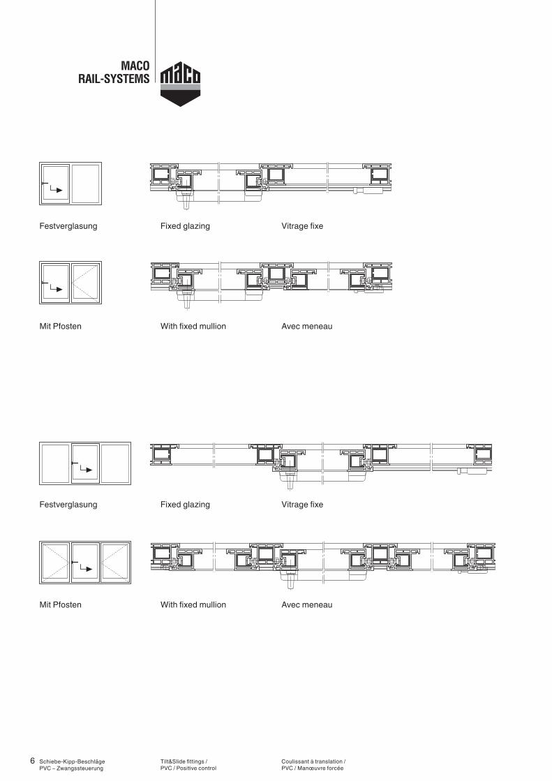
Mit Pfosten
Festverglasung
Festverglasung
Mit Pfosten
Tilt&Slide fittings / PVC / Positive control
With fixed mullion
Fixed glazing
Fixed glazing
With fixed mullion
Coulissant à translation / PVC / Manœuvre forcée
Avec meneau
Vitrage fixe
Vitrage fixe
Avec meneau
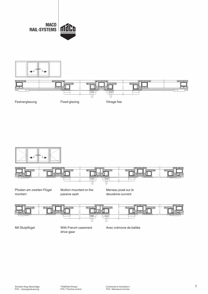
7Schiebe-Kipp-Beschläge PVC – Zwangssteuerung
Pfosten am zweiten Flügel montiert
Festverglasung
Mit Stulpflügel
Tilt&Slide fittings / PVC / Positive control
Mullion mounted on the passive sash
Fixed glazing
With French casement drive-gear
Coulissant à translation / PVC / Manœuvre forcée
Meneau posé sur le deuxième ouvrant
Vitrage fixe
Avec crémone de battée
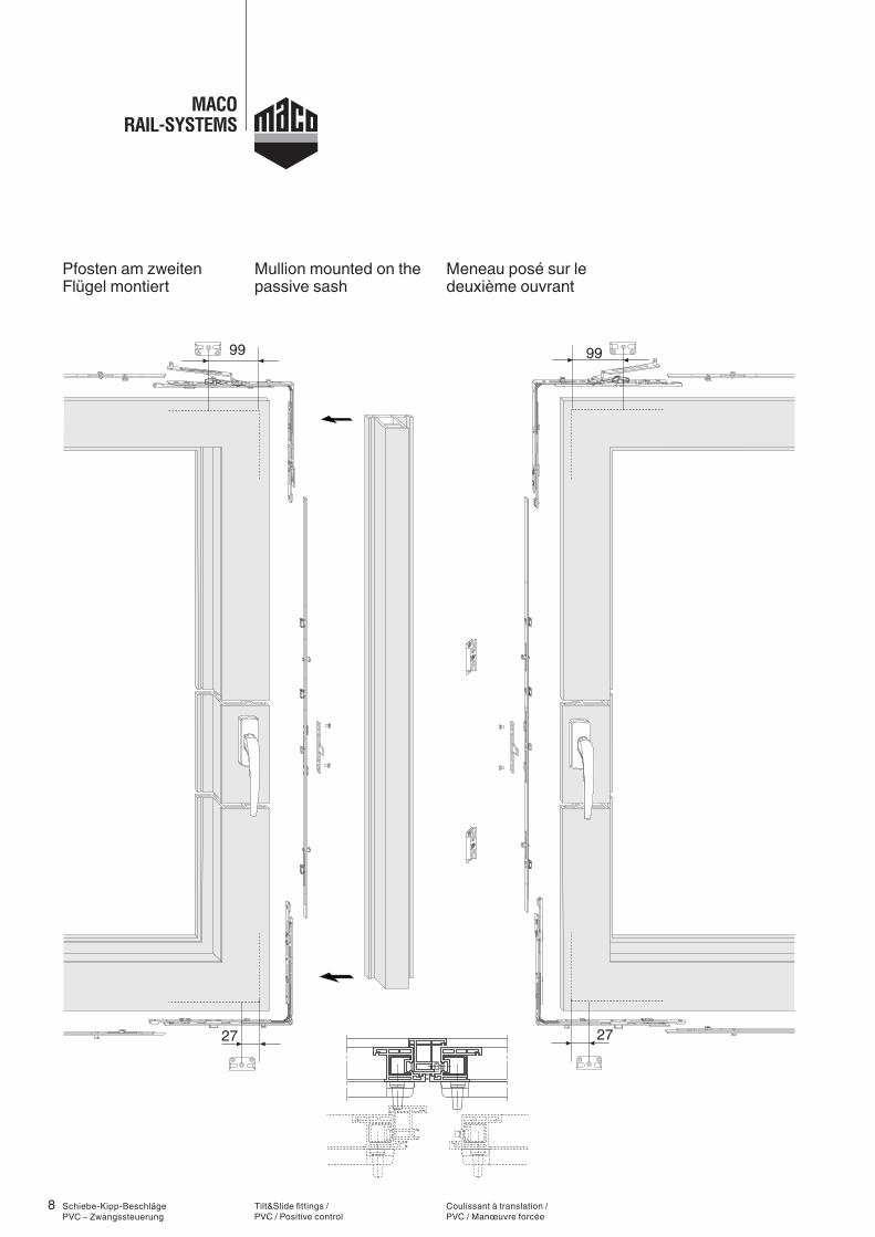
8
99
27
99
27
Schiebe-Kipp-Beschläge PVC – Zwangssteuerung
Pfosten am zweiten Flügel montiert
Tilt&Slide fittings / PVC / Positive control
Mullion mounted on the passive sash
Coulissant à translation / PVC / Manœuvre forcée
Meneau posé sur le deuxième ouvrant
9
99
27
99
27
Schiebe-Kipp-Beschläge PVC – Zwangssteuerung
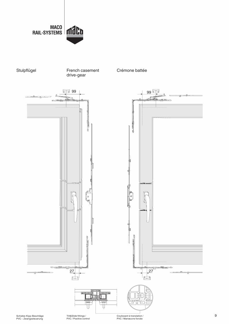
Stulpflügel
Tilt&Slide fittings / PVC / Positive control
French casement drive-gear
Coulissant à translation / PVC / Manœuvre forcée
Crémone battée
10
99 99
27 27
Schiebe-Kipp-Beschläge PVC – Zwangssteuerung
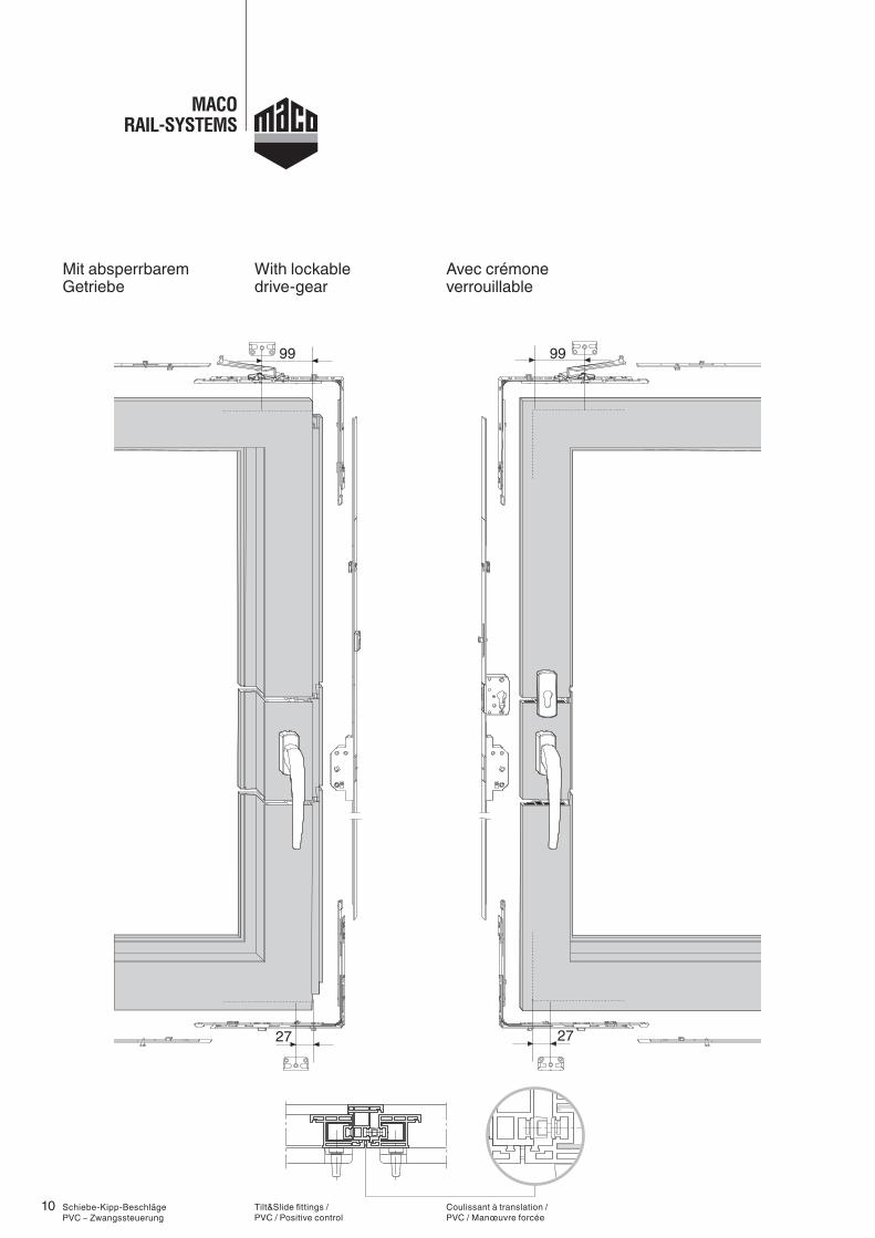
Mit absperrbarem Getriebe
Tilt&Slide fittings / PVC / Positive control
With lockable drive-gear
Coulissant à translation / PVC / Manœuvre forcée
Avec crémone verrouillable
11
93
120
88
112
10,5
6
Ø 4,2
Ø 4,2Ø 27Ø 6
0
21
3
15,5
∅ 4,2521 10,5
88 12093
112
3
∅ 6
15,5
6
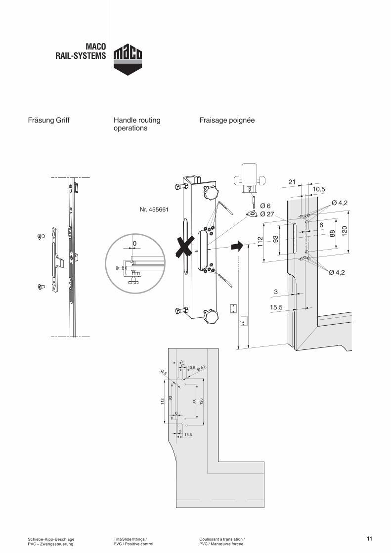
Nr. 455661
Schiebe-Kipp-Beschläge PVC – Zwangssteuerung
Fräsung Griff
Tilt&Slide fittings / PVC / Positive control
Handle routing operations
Coulissant à translation / PVC / Manœuvre forcée
Fraisage poignée
12
Ø 12(3x)
63
127
12 12,5
5045
17,5303540
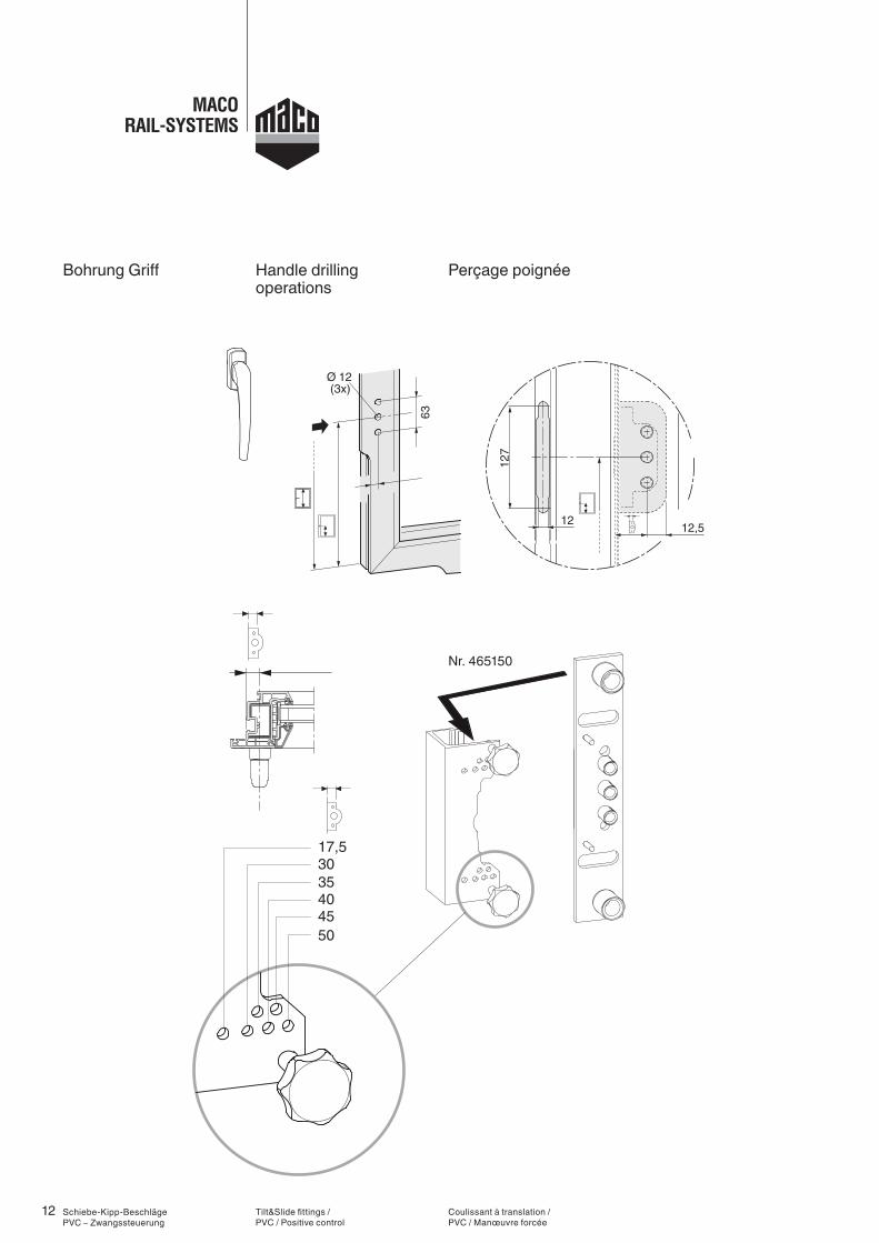
Nr. 465150
Schiebe-Kipp-Beschläge PVC – Zwangssteuerung
Bohrung Griff
Tilt&Slide fittings / PVC / Positive control
Handle drilling operations
Coulissant à translation / PVC / Manœuvre forcée
Perçage poignée
13
5045
17,5303540
1512,5
7644
,512
5
145,5
1663
145Ø 12
(3x)
Ø 20(2x)
63
145
16
0
63Ø 12(2x)
Schiebe-Kipp-Beschläge PVC – Zwangssteuerung
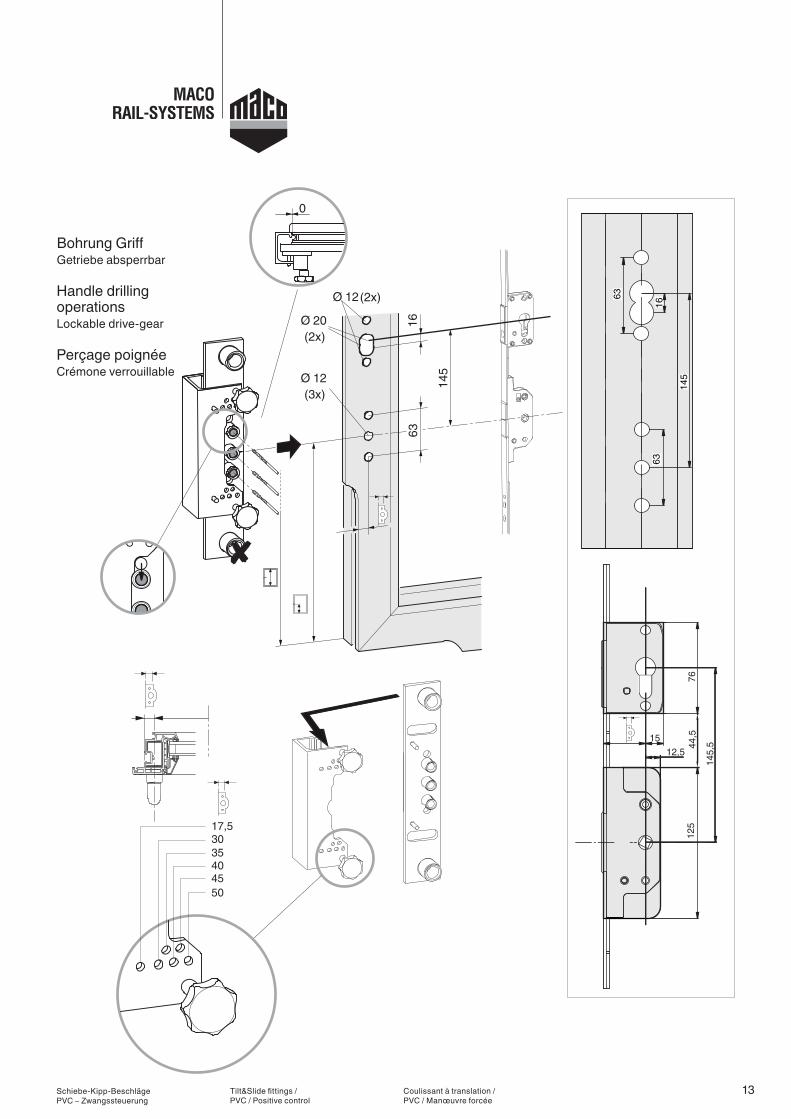
Bohrung GriffGetriebe absperrbar
Tilt&Slide fittings / PVC / Positive control
Handle drilling operationsLockable drive-gear
Coulissant à translation / PVC / Manœuvre forcée
Perçage poignéeCrémone verrouillable
14
����� ��� = =
Schiebe-Kipp-Beschläge PVC – Zwangssteuerung
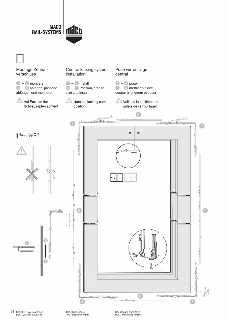
– montieren – anlegen, passend
ablängen und montieren
Auf Position der Schließzapfen achten!
Montage Zentral- verschluss
Tilt&Slide fittings / PVC / Positive control
– Install – Position, crop to
size and install
Note the locking cams position!
Central locking system installation
Coulissant à translation / PVC / Manœuvre forcée
– poser – mettre en place,
couper à longueur et poser
Veiller à la position des galets de verrouillage!
Pose verrouillage central
15
==
FFB720 - 850 mm
FFB851 - 1050 mm
FFB1051 - 2000 mm
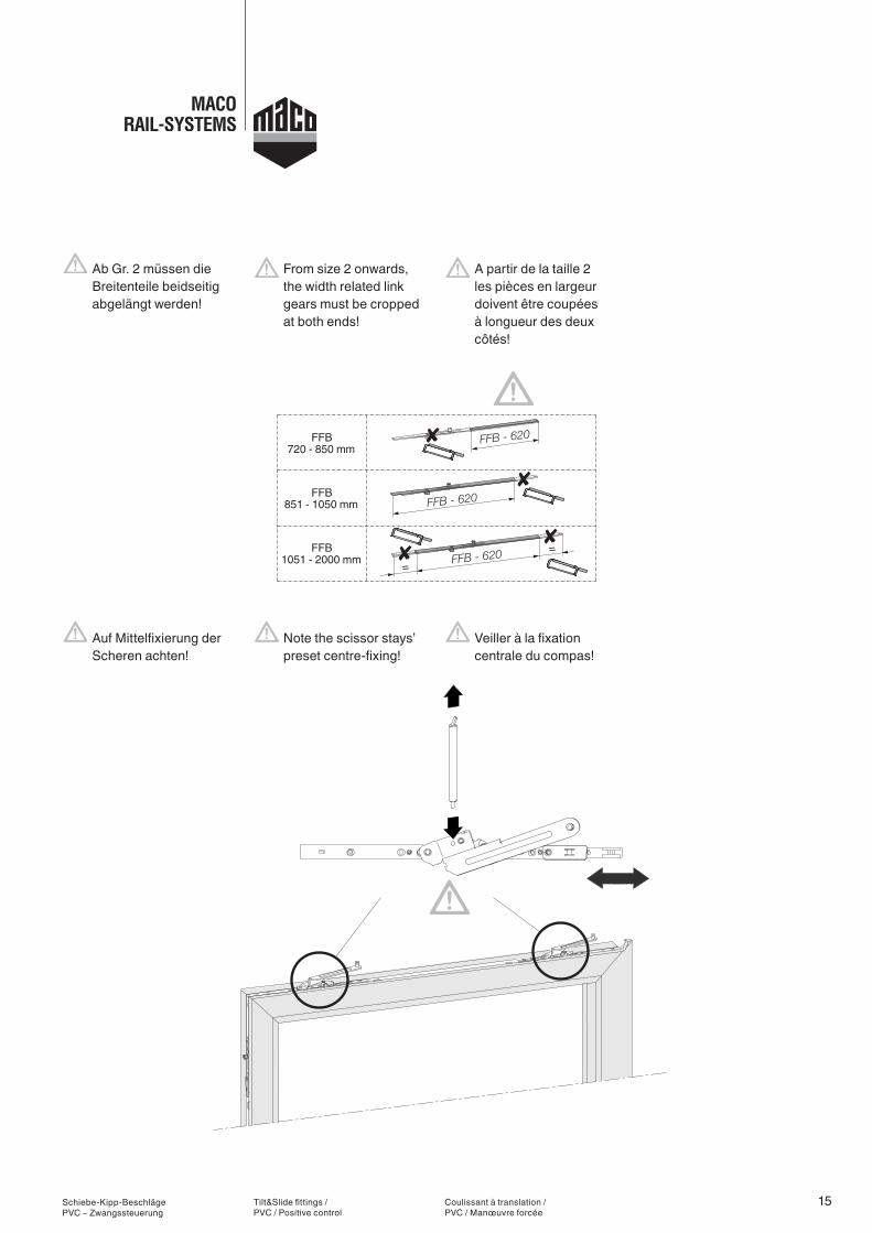
Schiebe-Kipp-Beschläge PVC – Zwangssteuerung
Auf Mittelfixierung der Scheren achten!
Ab Gr. 2 müssen die Breitenteile beidseitig abgelängt werden!
Tilt&Slide fittings / PVC / Positive control
Note the scissor stays’ preset centre-fixing!
From size 2 onwards, the width related link gears must be cropped at both ends!
Coulissant à translation / PVC / Manœuvre forcée
Veiller à la fixation centrale du compas!
A partir de la taille 2 les pièces en largeur doivent être coupées à longueur des deux côtés!
16
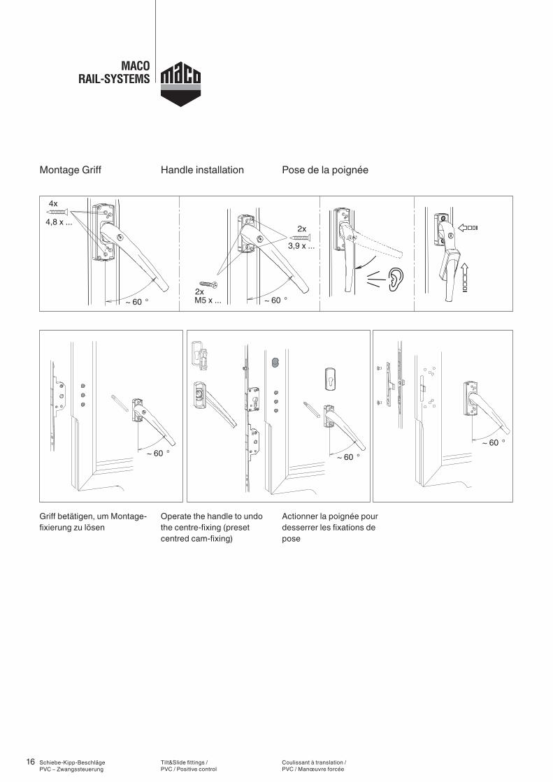
~ 60 ° ~ 60 °
4x
4,8 x ...2x
M5 x ...
3,9 x ...
2x
~ 60 °~ 60 °~ 60 °
Schiebe-Kipp-Beschläge PVC – Zwangssteuerung
Griff betätigen, um Montage-fixierung zu lösen
Montage Griff
Tilt&Slide fittings / PVC / Positive control
Operate the handle to undo the centre-fixing (preset centred cam-fixing)
Handle installation
Coulissant à translation / PVC / Manœuvre forcée
Actionner la poignée pour desserrer les fixations de pose
Pose de la poignée
17
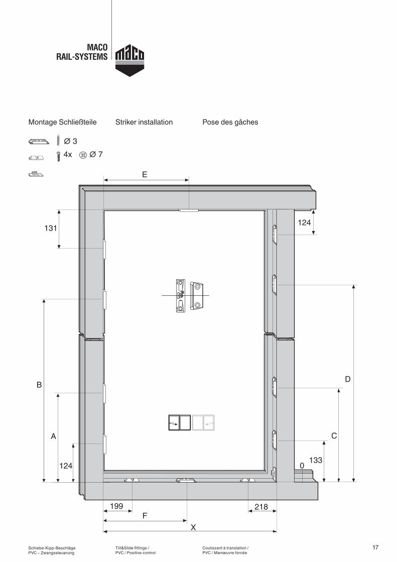
131
∅ 3∅ 74x
199 218F
X
0124
A
B
133
C
D
124
E
x
Schiebe-Kipp-Beschläge PVC – Zwangssteuerung
Montage Schließteile
Tilt&Slide fittings / PVC / Positive control
Striker installation
Coulissant à translation / PVC / Manœuvre forcée
Pose des gâches
18
E F
851-1050 534 447
1051-1450 ½ X – 4 ½ X + 4
1451-1850 ½ X – 4 ½ X + 4
1851-2000 ½ X – 4 ½ X + 4
==
FFB720 - 850 mm
FFB851 - 1050 mm
FFB1051 - 2000 mm
A B C D
900-1100 450 – – – –
1101-1300 450 719 – 726 –
1301-1500 650 469 919 476 926
1501-1700 650 469 1009 476 1016
1701-1900 950 719 1259 726 1266
1901-2100 950 719 1369 726 1376
2101-2300 950 719 1369 726 1376
2301-2400 950 719 1369 726 1376
Schiebe-Kipp-Beschläge PVC – Zwangssteuerung
Lehre Getriebe und Höhenteil:211611 + 211612Lehre Breitenteil: 211614
Tilt&Slide fittings / PVC / Positive control
Jig for drive-gear and height-related link gear:211611 + 211612Jig for width related link gear: 211614
Coulissant à translation / PVC / Manœuvre forcée
Gabarit crémone et pièce en hauteur 211611 + 211612Gabarit pièce en largeur: 211614
19
1010
Schiebe-Kipp-Beschläge PVC – Zwangssteuerung
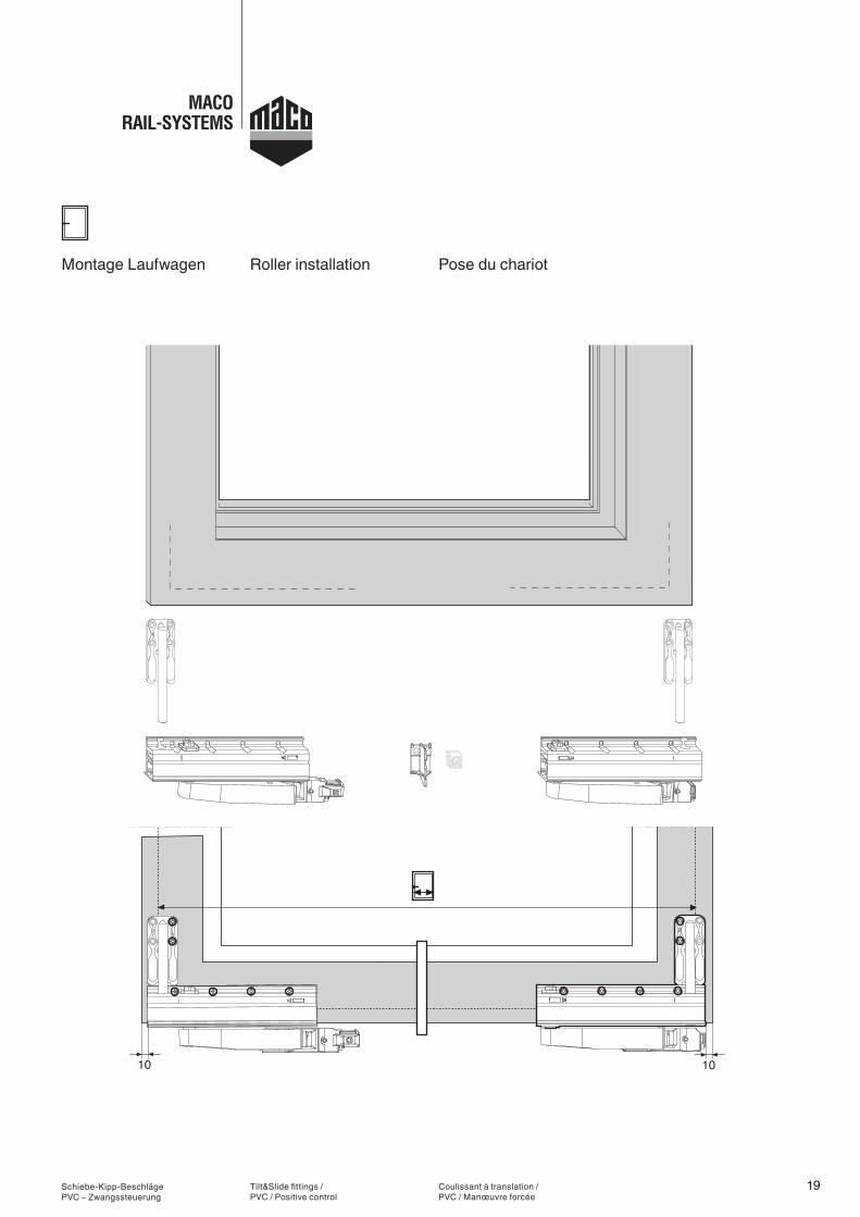
Montage Laufwagen
Tilt&Slide fittings / PVC / Positive control
Roller installation
Coulissant à translation / PVC / Manœuvre forcée
Pose du chariot
20
Y
0
0
0
10
x = 0, Y = 10 x > 0, Y = 10 + x x = 5, Y = 15
A
B
Ø 4,22 x
17
10
1314
411 4
15100kg
44
4
17
10
134 14
4114
15
100kg
S/A
S=StützeA=Abstützteil
SA
S
4
44 4
4Abstützteil
4S
Mitte
4
MLML
S/A
S=StützeA=Abstützteil
SA
S
4
44
17
10
1314
4
4
4Abstützteil
4
11
S
Mitte
4
4
15
LMLM
100kg4
4
x10
A
B
Ø 4,22 x
Ø 4,22 x
Ø 4,24 x
Ø 4,24 x
==
Schiebe-Kipp-Beschläge PVC – Zwangssteuerung
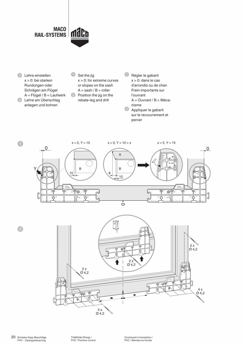
Lehre einstellen x > 0: bei starken
Rundungen oder Schrägen am Flügel
A = Flügel / B = Laufwerk Lehre am Überschlag
anlegen und bohren
Tilt&Slide fittings / PVC / Positive control
Set the jig x > 0: for extreme curves
or slopes on the sash A = sash / B = roller
Position the jig on the rebate-leg and drill
Coulissant à translation / PVC / Manœuvre forcée
Régler le gabarit x > 0: dans le cas
d’arrondis ou de chan Frein importants sur l’ouvrant
A = Ouvrant / B = Méca-nisme
Appliquer le gabarit sur le recouvrement et percer
21
Y
0
0
0
10
x = 0, Y = 10 x > 0, Y = 10 + x x = 5, Y = 15
A
B 17
10
1314
411 4
15100kg
44
4
17
10
134 14
4114
15
100kg
S/A
S=StützeA=Abstützteil
SA
S
4
44 4
4Abstützteil
4S
Mitte
4
MLML
S/A
S=StützeA=Abstützteil
SA
S
4
44
17
10
1314
4
4
4Abstützteil
4
11
S
Mitte
4
4
15
LMLM
100kg4
4 x10
A
B4
17
10
134 14
4114
15
100kg
S/A
S=StützeA=Abstützteil
SA
S
4
44 4
4Abstützteil
4S
Mitte
4
MLML
S/A
S=StützeA=Abstützteil
SA
S
4
44
17
10
1314
4
4
4Abstützteil
4
11
S
Mitte
4
4
15
LMLM
100kg4
4
Schiebe-Kipp-Beschläge PVC – Zwangssteuerung
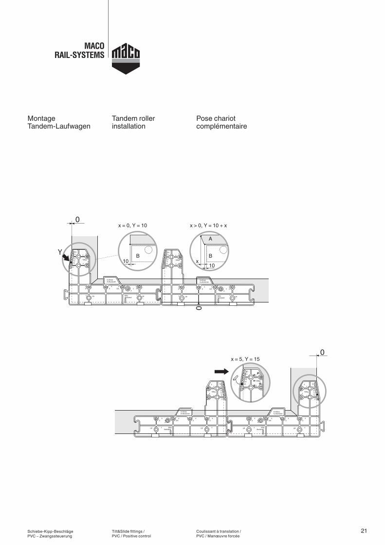
Montage Tandem-Laufwagen
Tilt&Slide fittings / PVC / Positive control
Tandem roller installation
Coulissant à translation / PVC / Manœuvre forcée
Pose chariot complémentaire
22
25
> 145025
25
4,8 x ...
a
a
b
b
Schiebe-Kipp-Beschläge PVC – Zwangssteuerung
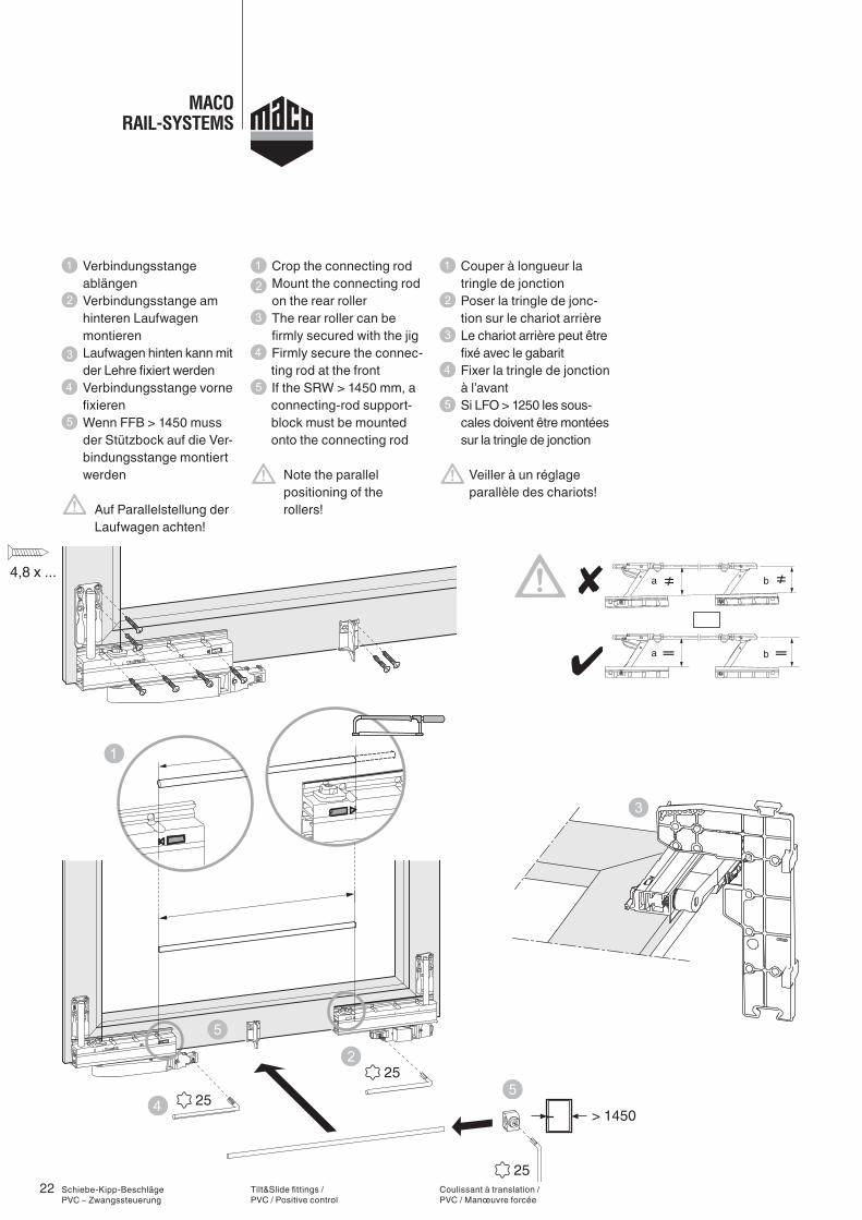
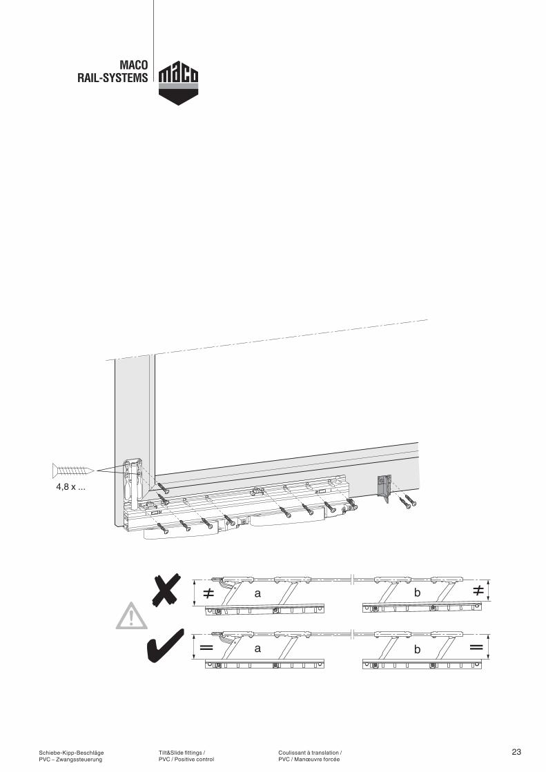
Verbindungsstange ablängen
Verbindungsstange am hinteren Laufwagen montieren
Laufwagen hinten kann mit der Lehre fixiert werden
Verbindungsstange vorne fixieren
Wenn FFB > 1450 muss der Stützbock auf die Ver-bindungsstange montiert werden
Auf Parallelstellung der Laufwagen achten!
Tilt&Slide fittings / PVC / Positive control
Crop the connecting rod Mount the connecting rod on the rear roller
The rear roller can be firmly secured with the jig
Firmly secure the connec-ting rod at the front If the SRW > 1450 mm, a connecting-rod support-block must be mounted onto the connecting rod
Note the parallel positioning of the rollers!
Coulissant à translation / PVC / Manœuvre forcée
Couper à longueur la tringle de jonction
Poser la tringle de jonc-tion sur le chariot arrière
Le chariot arrière peut être fixé avec le gabarit
Fixer la tringle de jonction à l’avant
Si LFO > 1250 les sous- cales doivent être montées sur la tringle de jonction
Veiller à un réglage parallèle des chariots!
23
4,8 x ...
a
a
b
b
Schiebe-Kipp-Beschläge PVC – Zwangssteuerung
Tilt&Slide fittings / PVC / Positive control
Coulissant à translation / PVC / Manœuvre forcée
24 Schiebe-Kipp-Beschläge PVC – Zwangssteuerung
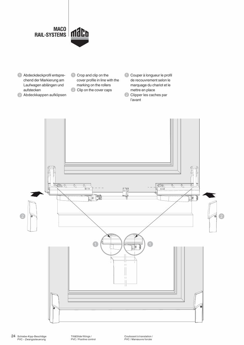
Abdeckdeckprofil entspre-chend der Markierung am Laufwagen ablängen und aufstecken
Abdeckkappen aufklipsen
Tilt&Slide fittings / PVC / Positive control
Crop and clip on the cover profile in line with the
marking on the rollers Clip on the cover caps
Coulissant à translation / PVC / Manœuvre forcée
Couper à longueur le profil de recouvrement selon le marquage du chariot et le mettre en place
Clipper les caches par l’avant
25
4 21
+ 8
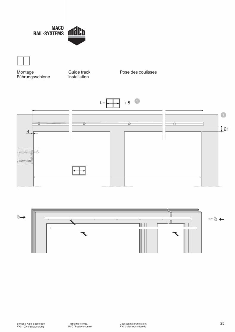
Schiebe-Kipp-Beschläge PVC – Zwangssteuerung
Montage Führungsschiene
Tilt&Slide fittings / PVC / Positive control
Guide track installation
Coulissant à translation / PVC / Manœuvre forcée
Pose des coulisses
26
4
4
Ø 3,2
33
1312
33
4x ...
Nr. 465173
Schiebe-Kipp-Beschläge PVC – Zwangssteuerung
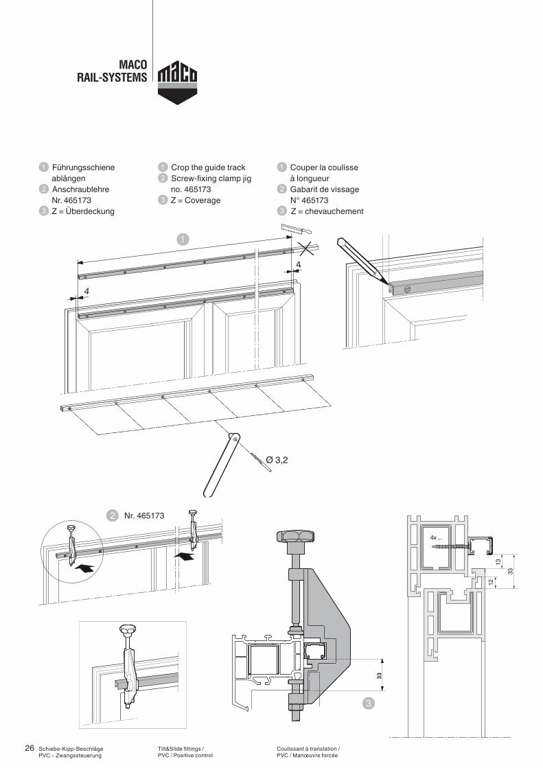
Führungsschiene ablängen Anschraublehre
Nr. 465173 Z = Überdeckung
Tilt&Slide fittings / PVC / Positive control
Crop the guide track Screw-fixing clamp jig
no. 465173 Z = Coverage
Coulissant à translation / PVC / Manœuvre forcée
Couper la coulisse à longueur
Gabarit de vissage N° 465173 Z = chevauchement
27
70
812
8*
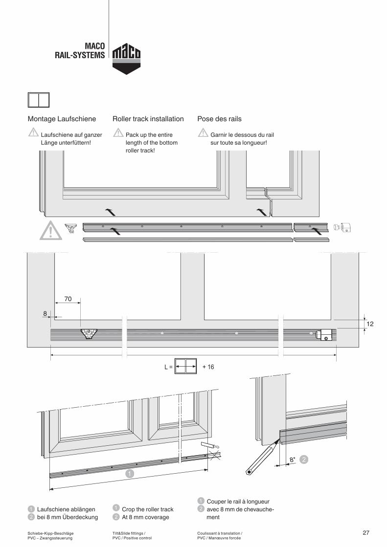
Schiebe-Kipp-Beschläge PVC – Zwangssteuerung
Montage Laufschiene
Laufschiene auf ganzer Länge unterfüttern!
Laufschiene ablängen bei 8 mm Überdeckung
Tilt&Slide fittings / PVC / Positive control
Roller track installation
Pack up the entire length of the bottom roller track!
Crop the roller track At 8 mm coverage
Coulissant à translation / PVC / Manœuvre forcée
Pose des rails
Garnir le dessous du rail sur toute sa longueur!
Couper le rail à longueur avec 8 mm de chevauche-ment
28
max.
4x...15 +
Z12 20
35 +
ZZ
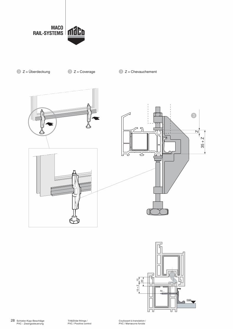
Schiebe-Kipp-Beschläge PVC – Zwangssteuerung
Z = Überdeckung
Tilt&Slide fittings / PVC / Positive control
Z = Coverage
Coulissant à translation / PVC / Manœuvre forcée
Z = Chevauchement
29
70
8
10
Nr. 465175
0
0
Schiebe-Kipp-Beschläge PVC – Zwangssteuerung
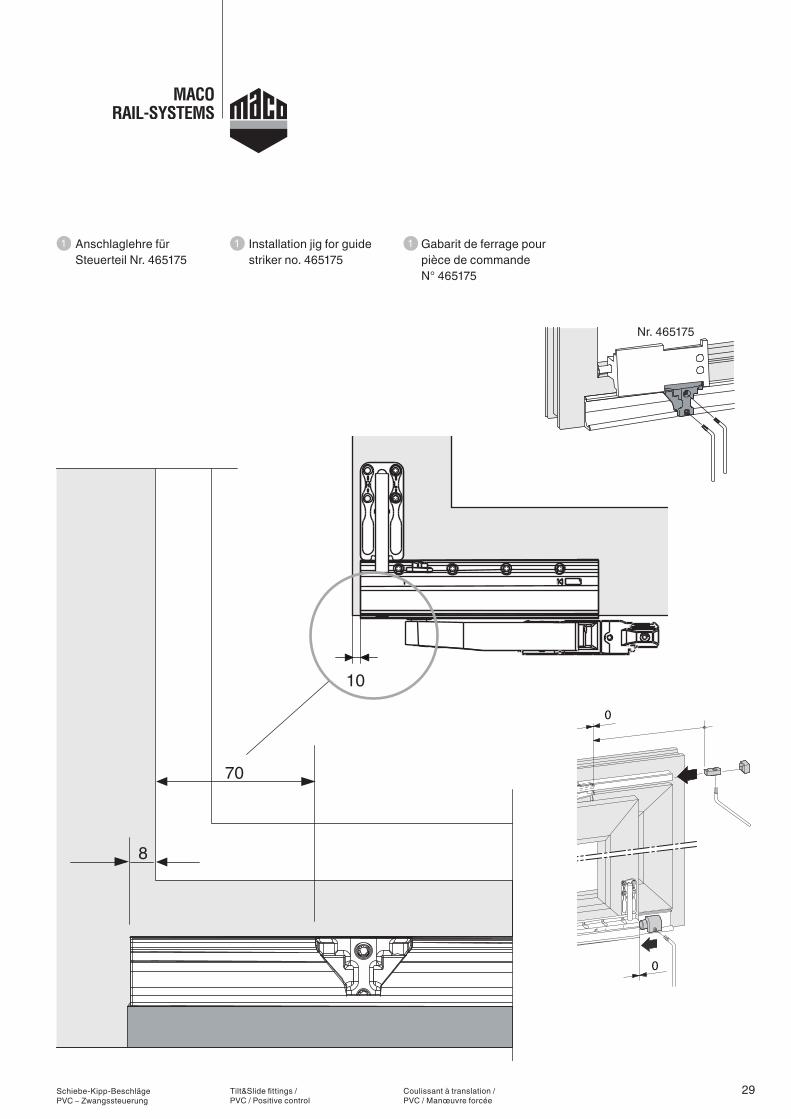
Anschlaglehre für Steuerteil Nr. 465175
Tilt&Slide fittings / PVC / Positive control
Installation jig for guide striker no. 465175
Coulissant à translation / PVC / Manœuvre forcée
Gabarit de ferrage pour pièce de commande N° 465175
30
>klick<
Schiebe-Kipp-Beschläge PVC – Zwangssteuerung
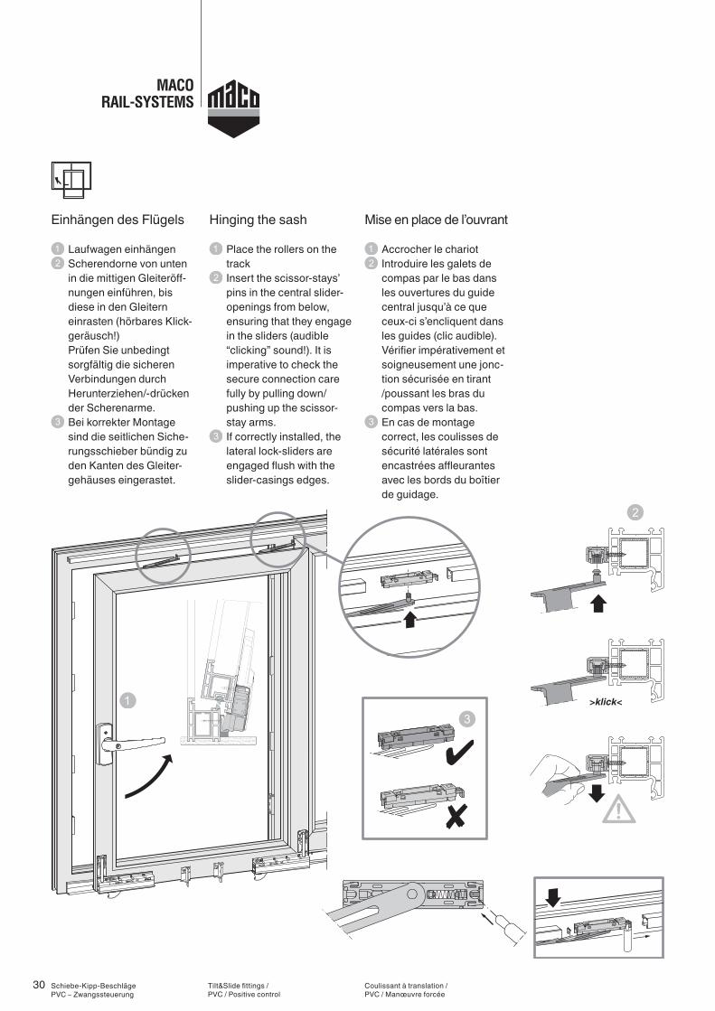
Einhängen des Flügels
Laufwagen einhängen Scherendorne von unten in die mittigen Gleiteröff-nungen einführen, bis diese in den Gleitern einrasten (hörbares Klick-geräusch!) Prüfen Sie unbedingt sorgfältig die sicheren Verbindungen durch Herunterziehen/-drücken der Scherenarme.
Bei korrekter Montage sind die seitlichen Siche-rungsschieber bündig zu den Kanten des Gleiter-gehäuses eingerastet.
Tilt&Slide fittings / PVC / Positive control
Hinging the sash
Place the rollers on the track
Insert the scissor-stays’ pins in the central slider- openings from below, ensuring that they engage in the sliders (audible “clicking” sound!). It is imperative to check the secure connection care fully by pulling down/ pushing up the scissor- stay arms.
If correctly installed, the lateral lock-sliders are engaged flush with the slider-casings edges.
Coulissant à translation / PVC / Manœuvre forcée
Mise en place de l’ouvrant
Accrocher le chariot Introduire les galets de compas par le bas dans les ouvertures du guide central jusqu’à ce que ceux-ci s’encliquent dans les guides (clic audible). Vérifier impérativement et soigneusement une jonc-tion sécurisée en tirant /poussant les bras du compas vers la bas.
En cas de montage correct, les coulisses de sécurité latérales sont encastrées affleurantes avec les bords du boîtier de guidage.
31
a b
Schiebe-Kipp-Beschläge PVC – Zwangssteuerung
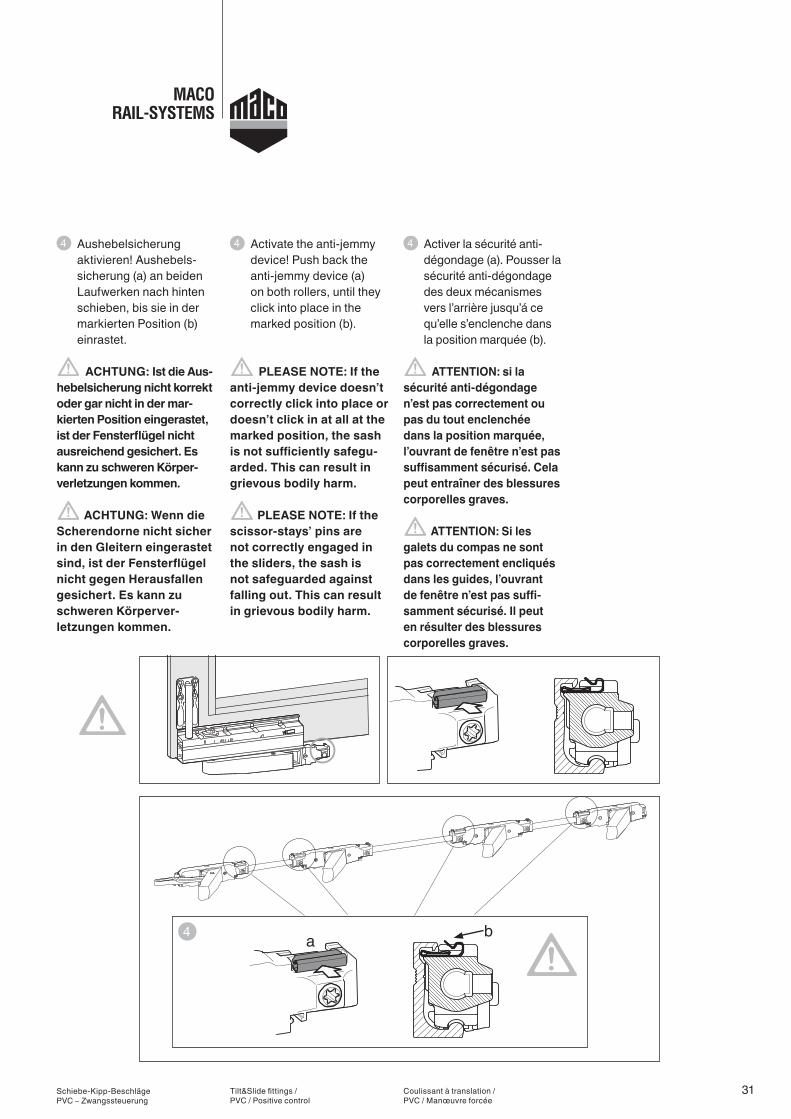
Aushebelsicherung aktivieren! Aushebels-sicherung (a) an beiden Laufwerken nach hinten schieben, bis sie in der markierten Position (b) einrastet.
ACHTUNG: Ist die Aus-hebelsicherung nicht korrekt oder gar nicht in der mar-kierten Position eingerastet, ist der Fensterflügel nicht ausreichend gesichert. Es kann zu schweren Körper-verletzungen kommen.
ACHTUNG: Wenn die Scherendorne nicht sicher in den Gleitern eingerastet sind, ist der Fensterflügel nicht gegen Herausfallen gesichert. Es kann zu schweren Körperver- letzungen kommen.
Tilt&Slide fittings / PVC / Positive control
Activate the anti-jemmy device! Push back the anti-jemmy device (a) on both rollers, until they click into place in the marked position (b).
PLEASE NOTE: If the anti-jemmy device doesn’t correctly click into place or doesn’t click in at all at the marked position, the sash is not sufficiently safegu-arded. This can result in grievous bodily harm.
PLEASE NOTE: If the scissor-stays’ pins are not correctly engaged in the sliders, the sash is not safeguarded against falling out. This can result in grievous bodily harm.
Coulissant à translation / PVC / Manœuvre forcée
Activer la sécurité anti-dégondage (a). Pousser la sécurité anti-dégondage des deux mécanismes vers l’arrière jusqu’á ce qu’elle s’enclenche dans la position marquée (b).
ATTENTION: si la sécurité anti-dégondage n’est pas correctement ou pas du tout enclenchée dans la position marquée, l’ouvrant de fenêtre n’est pas suffisamment sécurisé. Cela peut entraîner des blessures corporelles graves.
ATTENTION: Si les galets du compas ne sont pas correctement encliqués dans les guides, l’ouvrant de fenêtre n’est pas suffi-samment sécurisé. Il peut en résulter des blessures corporelles graves.
32
40
a
a
b
b
+
Schiebe-Kipp-Beschläge PVC – Zwangssteuerung
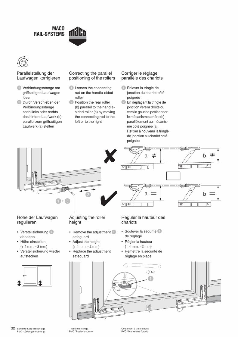
Parallelstellung der Laufwagen korrigieren
Verbindungsstange am griffseitigen Laufwagen lösen
Durch Verschieben der Verbindungsstange nach links oder rechts das hintere Laufwerk (b) parallel zum griffseitigen Laufwerk (a) stellen
Höhe der Laufwagen regulieren
• Verstellsicherung abheben
• Höhe einstellen (+ 4 mm, - 2 mm)
• Verstellsicherung wieder aufstecken
Tilt&Slide fittings / PVC / Positive control
Correcting the parallel positioning of the rollers
Loosen the connecting rod on the handle-sided roller
Position the rear roller (b) parallel to the handle-sided roller (a) by moving the connecting rod to the left or to the right
Adjusting the roller height
• Remove the adjustment safeguard
• Adjust the height (+ 4 mm, - 2 mm)• Replace the adjustment
safeguard
Coulissant à translation / PVC / Manœuvre forcée
Corriger le réglage parallèle des chariots
Enlever la tringle de jonction du chariot côté poignée
En déplaçant la tringle de jonction vers la droite ou vers la gauche positionner le mécanisme arrière (b) parallèlement au mécanis-me côté poignée (a) Refixer à nouveau la tringle de jonction au chariot coté poignée
Réguler la hauteur des chariots
• Soulever la sécurité de réglage
• Régler la hauteur (+ 4 mm, - 2 mm)• Remettre la sécurité de
réglage en place
33Schiebe-Kipp-Beschläge PVC – Zwangssteuerung
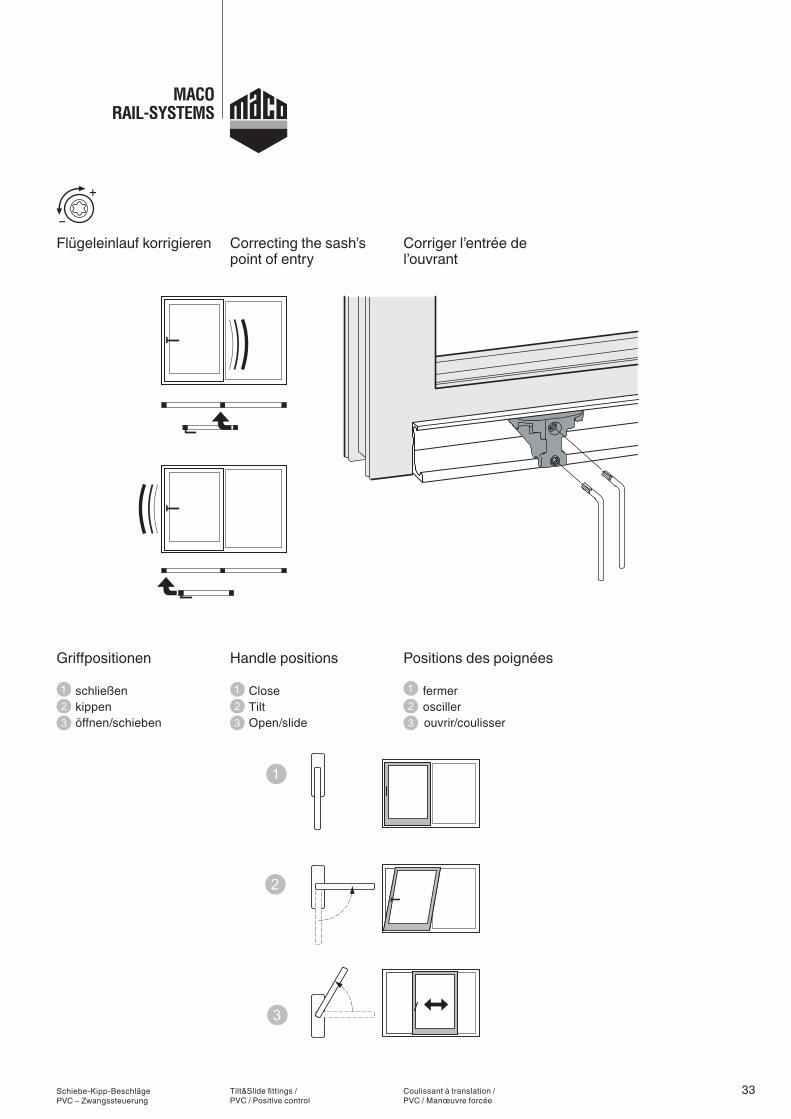
schließen kippen öffnen/schieben
Flügeleinlauf korrigieren
Griffpositionen
Tilt&Slide fittings / PVC / Positive control
Close Tilt Open/slide
Correcting the sash’s point of entry
Handle positions
Coulissant à translation / PVC / Manœuvre forcée
fermer osciller ouvrir/coulisser
Corriger l’entrée de l’ouvrant
Positions des poignées

Notizen
Schiebe-Kipp-Beschläge PVC – Zwangssteuerung
Tilt&Slide fittings / PVC / Positive control
Notes
Coulissant à translation / PVC / Manœuvre forcée
Notities
Notizen
Schiebe-Kipp-Beschläge PVC – Zwangssteuerung
Tilt&Slide fittings / PVC / Positive control
Notes
Coulissant à translation / PVC / Manœuvre forcée
Notities

TECHNIK DIE BEWEGT
MAYER & CO BESCHLÄGE GMBHALPENSTRASSE 173
A-5020 SALZBURGTEL +43 (0)662 6196-0
FAX +43 (0)662 [email protected]
www.maco.atBest.-Nr. 756545 - Datum: Mai 2009
Alle Rechte und Änderungen vorbehalten.


