erweiterungsset (4.0) für ca fotostativ expansion set (4.0...
TRANSCRIPT

Erweiterungsset (4.0) für CA® FotostativExpansion set (4.0) for CA® photo support
REF 5313.1
2
Erweiterungsset (4.0) für CA® Fotostativ
Das Erweiterungsset enthält zwei Höhenfixierblöcke für die Höhenverstellung der Kamera zur Anfertigung von folgenden Aufnahmen:1. Okklusal (Oberkiefer oder Unterkiefer)2. Frontal (Oberkiefer oder Unterkiefer)3. Lateral – Links/Rechts (Oberkiefer oder Unterkiefer)4. Vestibulär (Oberkiefer und Unterkiefer)
Hinweis: Sie benötigen für einen Kiefer zwei Höhenfixierblöcke, d.h. für Aufnahmen von Oberkiefer und Unterkiefer werden zwei Erweiterungssets benötigt! Die Hartgipsmodelle sollten eine maximale Höhe von 25 mm nicht überschreiten.
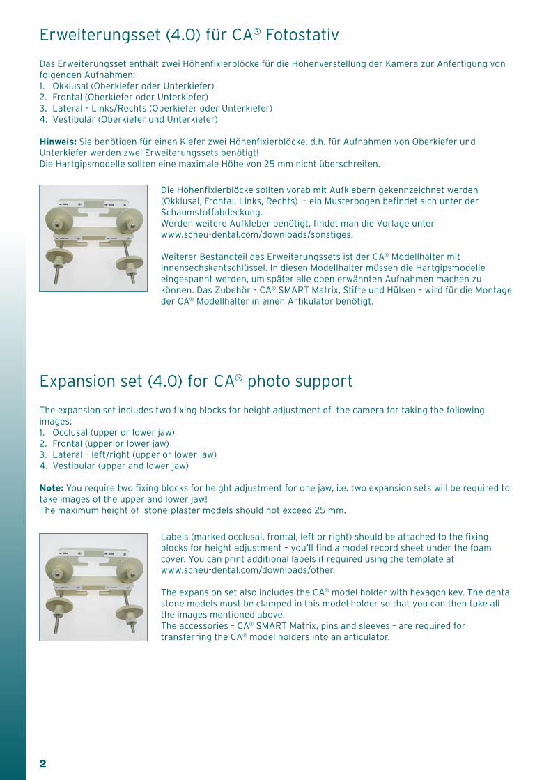
Die Höhenfixierblöcke sollten vorab mit Aufklebern gekennzeichnet werden (Okklusal, Frontal, Links, Rechts) – ein Musterbogen befindet sich unter der Schaumstoffabdeckung. Werden weitere Aufkleber benötigt, findet man die Vorlage unter www.scheu-dental.com/downloads/sonstiges.
Weiterer Bestandteil des Erweiterungssets ist der CA® Modellhalter mit Innensechskantschlüssel. In diesen Modellhalter müssen die Hartgipsmodelle eingespannt werden, um später alle oben erwähnten Aufnahmen machen zu können. Das Zubehör – CA® SMART Matrix, Stifte und Hülsen – wird für die Montage der CA® Modellhalter in einen Artikulator benötigt.
Expansion set (4.0) for CA® photo support
The expansion set includes two fixing blocks for height adjustment of the camera for taking the following images:1. Occlusal (upper or lower jaw)2. Frontal (upper or lower jaw)3. Lateral – left/right (upper or lower jaw)4. Vestibular (upper and lower jaw)
Note: You require two fixing blocks for height adjustment for one jaw, i.e. two expansion sets will be required to take images of the upper and lower jaw!The maximum height of stone-plaster models should not exceed 25 mm.
Labels (marked occlusal, frontal, left or right) should be attached to the fixing blocks for height adjustment – you’ll find a model record sheet under the foam cover. You can print additional labels if required using the template at www.scheu-dental.com/downloads/other.
The expansion set also includes the CA® model holder with hexagon key. The dental stone models must be clamped in this model holder so that you can then take all the images mentioned above.The accessories – CA® SMART Matrix, pins and sleeves – are required for transferring the CA® model holders into an articulator.
3
Umbau des Fotostativs: Ziel: Entfernung des unteren Anschlags/Feststellring
1. USB-Verbindung zum Computer trennen.
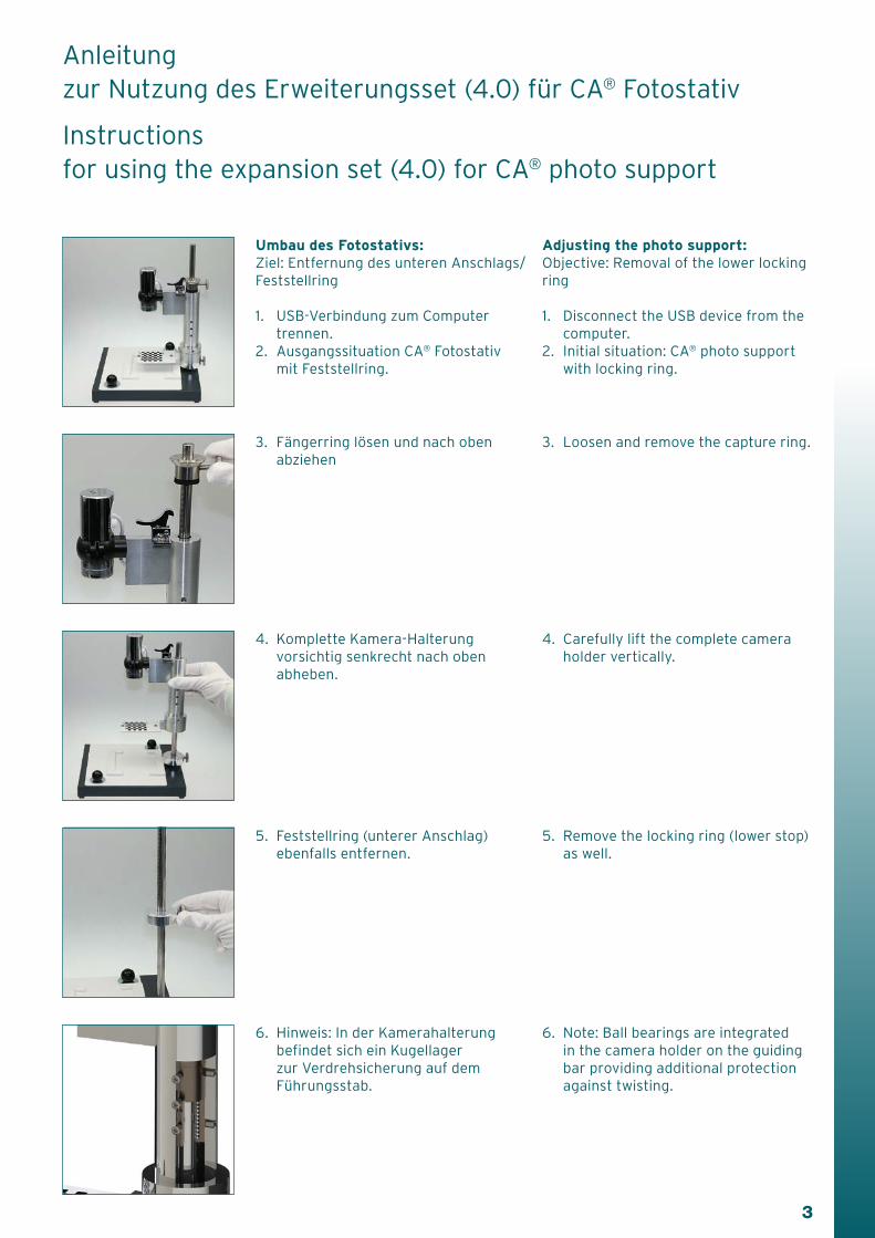
2. Ausgangssituation CA® Fotostativ mit Feststellring.
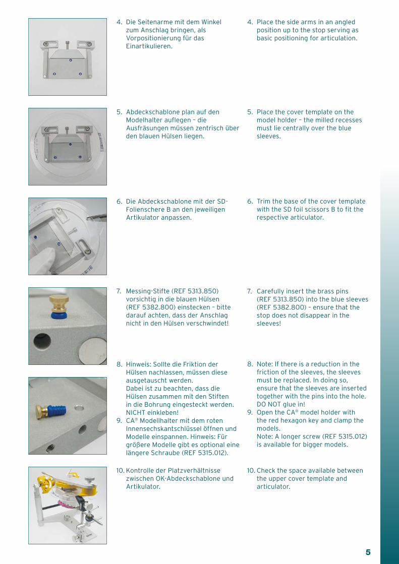
4. Komplette Kamera-Halterung vorsichtig senkrecht nach oben abheben.
5. Feststellring (unterer Anschlag) ebenfalls entfernen.
6. Hinweis: In der Kamerahalterung befindet sich ein Kugellager zur Verdrehsicherung auf dem Führungsstab.
Anleitung zur Nutzung des Erweiterungsset (4.0) für CA® Fotostativ
Instructions for using the expansion set (4.0) for CA® photo support
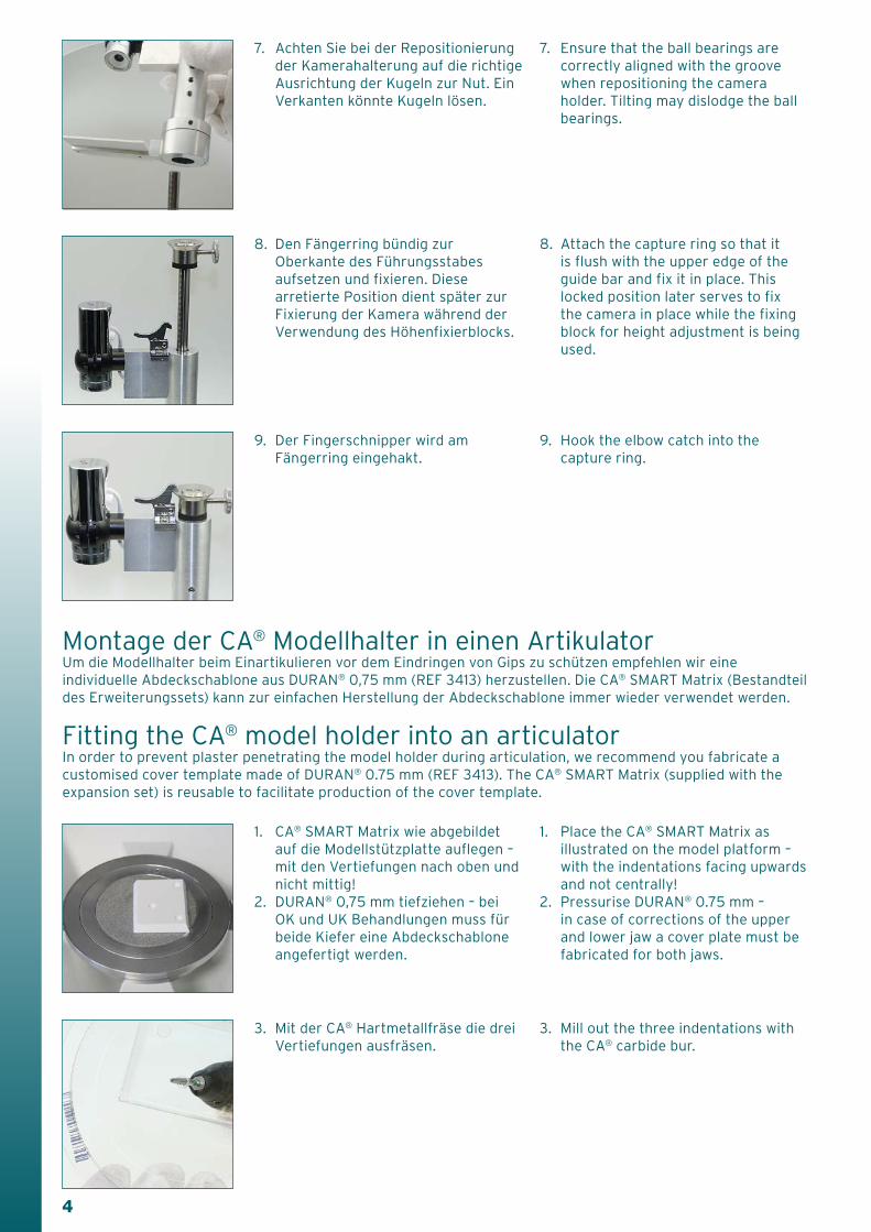
3. Fängerring lösen und nach oben abziehen
3. Loosen and remove the capture ring.
4. Carefully lift the complete camera holder vertically.
Adjusting the photo support: Objective: Removal of the lower locking ring
1. Disconnect the USB device from the computer.
2. Initial situation: CA® photo support with locking ring.
5. Remove the locking ring (lower stop) as well.
6. Note: Ball bearings are integrated in the camera holder on the guiding bar providing additional protection against twisting.
4
8. Den Fängerring bündig zur Oberkante des Führungsstabes aufsetzen und fixieren. Diese arretierte Position dient später zur Fixierung der Kamera während der Verwendung des Höhenfixierblocks.
9. Der Fingerschnipper wird am Fängerring eingehakt.
1. CA® SMART Matrix wie abgebildet auf die Modellstützplatte auflegen – mit den Vertiefungen nach oben und nicht mittig!
2. DURAN® 0,75 mm tiefziehen – bei OK und UK Behandlungen muss für beide Kiefer eine Abdeckschablone angefertigt werden.
3. Mit der CA® Hartmetallfräse die drei Vertiefungen ausfräsen.
7. Achten Sie bei der Repositionierung der Kamerahalterung auf die richtige Ausrichtung der Kugeln zur Nut. Ein Verkanten könnte Kugeln lösen.
Montage der CA® Modellhalter in einen ArtikulatorUm die Modellhalter beim Einartikulieren vor dem Eindringen von Gips zu schützen empfehlen wir eine individuelle Abdeckschablone aus DURAN® 0,75 mm (REF 3413) herzustellen. Die CA® SMART Matrix (Bestandteil des Erweiterungssets) kann zur einfachen Herstellung der Abdeckschablone immer wieder verwendet werden.
Fitting the CA® model holder into an articulator In order to prevent plaster penetrating the model holder during articulation, we recommend you fabricate a customised cover template made of DURAN® 0.75 mm (REF 3413). The CA® SMART Matrix (supplied with the expansion set) is reusable to facilitate production of the cover template.
8. Attach the capture ring so that it is flush with the upper edge of the guide bar and fix it in place. This locked position later serves to fix the camera in place while the fixing block for height adjustment is being used.
7. Ensure that the ball bearings are correctly aligned with the groove when repositioning the camera holder. Tilting may dislodge the ball bearings.
9. Hook the elbow catch into the capture ring.
3. Mill out the three indentations with the CA® carbide bur.
1. Place the CA® SMART Matrix as illustrated on the model platform – with the indentations facing upwards and not centrally!
2. Pressurise DURAN® 0.75 mm – in case of corrections of the upper and lower jaw a cover plate must be fabricated for both jaws.
5
5. Abdeckschablone plan auf den Modelhalter auflegen – die Ausfräsungen müssen zentrisch über den blauen Hülsen liegen.
6. Die Abdeckschablone mit der SD-Folienschere B an den jeweiligen Artikulator anpassen.
7. Messing-Stifte (REF 5313.850) vorsichtig in die blauen Hülsen (REF 5382.800) einstecken – bitte darauf achten, dass der Anschlag nicht in den Hülsen verschwindet!
8. Hinweis: Sollte die Friktion der Hülsen nachlassen, müssen diese ausgetauscht werden. Dabei ist zu beachten, dass die Hülsen zusammen mit den Stiften in die Bohrung eingesteckt werden. NICHT einkleben!
9. CA® Modellhalter mit dem roten Innensechskantschlüssel öffnen und Modelle einspannen. Hinweis: Für größere Modelle gibt es optional eine längere Schraube (REF 5315.012).
10. Kontrolle der Platzverhältnisse zwischen OK-Abdeckschablone und Artikulator.
4. Die Seitenarme mit dem Winkel zum Anschlag bringen, als Vorpositionierung für das Einartikulieren.
4. Place the side arms in an angled position up to the stop serving as basic positioning for articulation.
5. Place the cover template on the model holder – the milled recesses must lie centrally over the blue sleeves.
10. Check the space available between the upper cover template and articulator.
8. Note: If there is a reduction in the friction of the sleeves, the sleeves must be replaced. In doing so, ensure that the sleeves are inserted together with the pins into the hole. DO NOT glue in!
9. Open the CA® model holder with the red hexagon key and clamp the models. Note: A longer screw (REF 5315.012) is available for bigger models.
6. Trim the base of the cover template with the SD foil scissors B to fit the respective articulator.
7. Carefully insert the brass pins (REF 5313.850) into the blue sleeves (REF 5382.800) – ensure that the stop does not disappear in the sleeves!
6
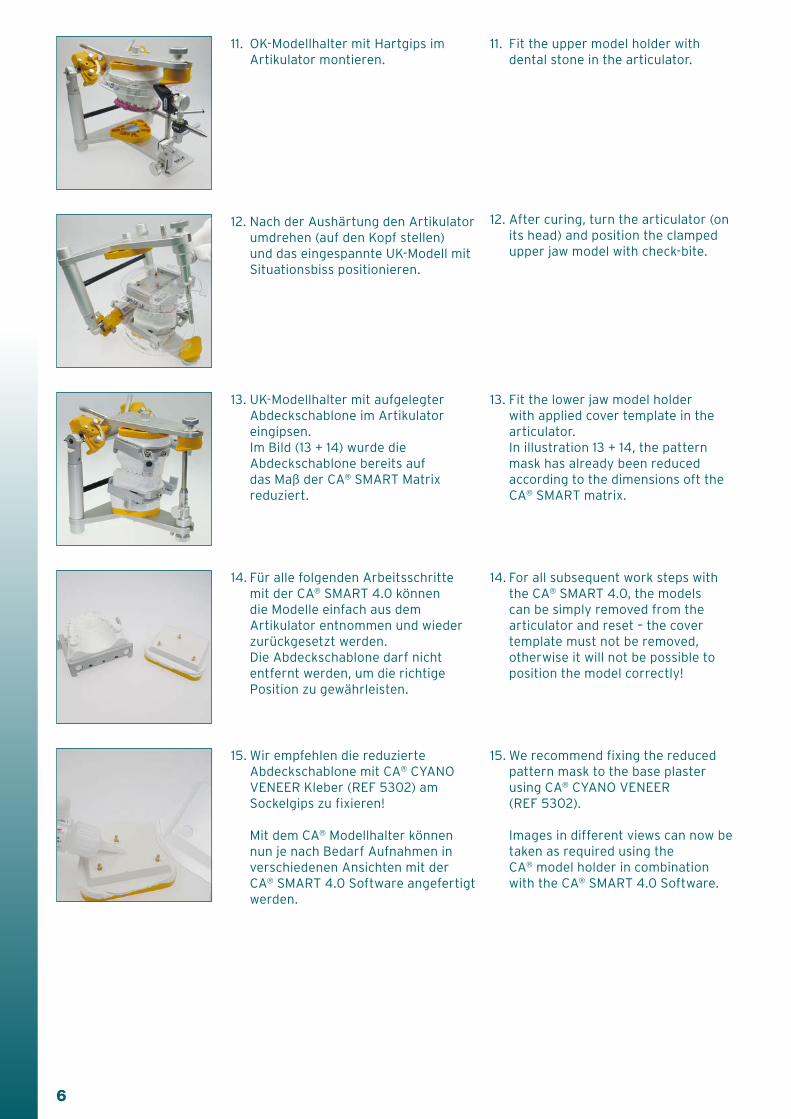
12. Nach der Aushärtung den Artikulator umdrehen (auf den Kopf stellen) und das eingespannte UK-Modell mit Situationsbiss positionieren.
13. UK-Modellhalter mit aufgelegter Abdeckschablone im Artikulator eingipsen.
Im Bild (13 + 14) wurde die Abdeckschablone bereits auf das Maß der CA® SMART Matrix reduziert.
14. Für alle folgenden Arbeitsschritte mit der CA® SMART 4.0 können die Modelle einfach aus dem Artikulator entnommen und wieder zurückgesetzt werden. Die Abdeckschablone darf nicht entfernt werden, um die richtige Position zu gewährleisten.
15. Wir empfehlen die reduzierte Abdeckschablone mit CA® CYANO VENEER Kleber (REF 5302) am Sockelgips zu fixieren!
11. OK-Modellhalter mit Hartgips im Artikulator montieren.
11. Fit the upper model holder with dental stone in the articulator.
12. After curing, turn the articulator (on its head) and position the clamped upper jaw model with check-bite.
13. Fit the lower jaw model holder with applied cover template in the articulator.
In illustration 13 + 14, the pattern mask has already been reduced according to the dimensions oft the CA® SMART matrix.
14. For all subsequent work steps with the CA® SMART 4.0, the models can be simply removed from the articulator and reset – the cover template must not be removed, otherwise it will not be possible to position the model correctly!
Mit dem CA® Modellhalter können nun je nach Bedarf Aufnahmen in verschiedenen Ansichten mit der CA® SMART 4.0 Software angefertigt werden.
15. We recommend fixing the reduced pattern mask to the base plaster using CA® CYANO VENEER (REF 5302).
Images in different views can now be taken as required using the CA® model holder in combination with the CA® SMART 4.0 Software.

7
1. Aufsetzen des Höhenfixierblocks an der hinteren Kante der Grundplatte.
2. Höhenfixierblock zur gewünschten Seite für die okklusale Aufnahme schieben.
3. Absenken der Kamerahalterung auf den Anschlagteller.
4. CA® Modellhalter mit vorbereitetem Hartgipsmodell auf die Grundplatte stellen.
5. Einstellung der exakten Messebene durch Drehen des Anschlagtellers.
Verwendung der beiden Höhenfixierblöcke in Verbindung mit dem CA® Modellhalter
Using the two fixing blocks for height adjustment in combination with the CA® model holder
6. Abschließend wird durch Anziehen der kleinen Kontermutter die Höheneinstellung gesichert. Die Stellung des Anschlagtellers wird beibehalten!
1. Place the fixing block for height adjustment on the rear edge of the base plate.
2. To take occlusal images, push the fixing block for height adjustment to the required side.
3. Lower the camera holder down to the stop plate.
4. Place the CA® model holder with prepared dental stone model on the base plate.
5. Set the exact measurement level by turning the plate.
6. Finally, secure the height position required by tightening the counter nuts and maintaining the position of the stop plate.
8
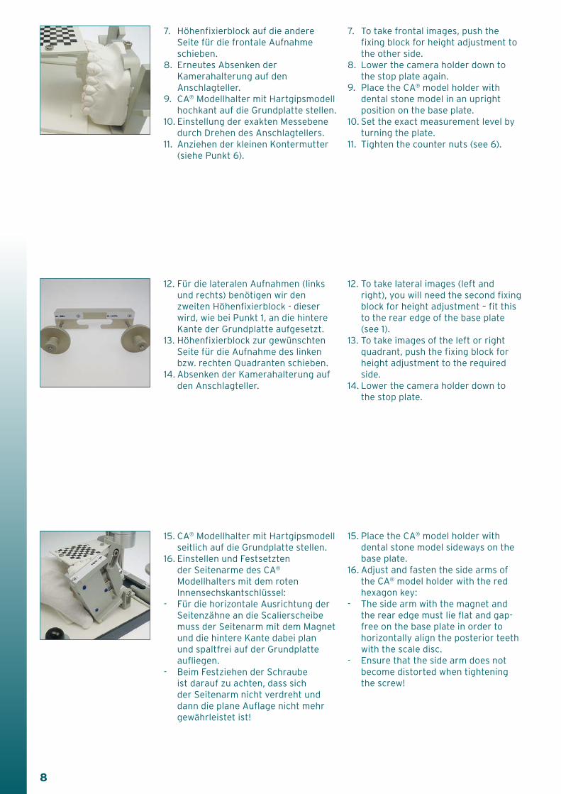
7. Höhenfixierblock auf die andere Seite für die frontale Aufnahme schieben.
8. Erneutes Absenken der Kamerahalterung auf den Anschlagteller.
9. CA® Modellhalter mit Hartgipsmodell hochkant auf die Grundplatte stellen.
10. Einstellung der exakten Messebene durch Drehen des Anschlagtellers.
11. Anziehen der kleinen Kontermutter (siehe Punkt 6).
12. Für die lateralen Aufnahmen (links und rechts) benötigen wir den zweiten Höhenfixierblock - dieser wird, wie bei Punkt 1, an die hintere Kante der Grundplatte aufgesetzt.
13. Höhenfixierblock zur gewünschten Seite für die Aufnahme des linken bzw. rechten Quadranten schieben.
14. Absenken der Kamerahalterung auf den Anschlagteller.
15. CA® Modellhalter mit Hartgipsmodell seitlich auf die Grundplatte stellen.
16. Einstellen und Festsetzten der Seitenarme des CA® Modellhalters mit dem roten Innensechskantschlüssel:
- Für die horizontale Ausrichtung der Seitenzähne an die Scalierscheibe muss der Seitenarm mit dem Magnet und die hintere Kante dabei plan und spaltfrei auf der Grundplatte aufliegen.
- Beim Festziehen der Schraube ist darauf zu achten, dass sich der Seitenarm nicht verdreht und dann die plane Auflage nicht mehr gewährleistet ist!
7. To take frontal images, push the fixing block for height adjustment to the other side.
8. Lower the camera holder down to the stop plate again.
9. Place the CA® model holder with dental stone model in an upright position on the base plate.
10. Set the exact measurement level by turning the plate.
11. Tighten the counter nuts (see 6).
12. To take lateral images (left and right), you will need the second fixing block for height adjustment – fit this to the rear edge of the base plate (see 1).
13. To take images of the left or right quadrant, push the fixing block for height adjustment to the required side.
14. Lower the camera holder down to the stop plate.
15. Place the CA® model holder with dental stone model sideways on the base plate.
16. Adjust and fasten the side arms of the CA® model holder with the red hexagon key:
- The side arm with the magnet and the rear edge must lie flat and gap-free on the base plate in order to horizontally align the posterior teeth with the scale disc.
- Ensure that the side arm does not become distorted when tightening the screw!
9
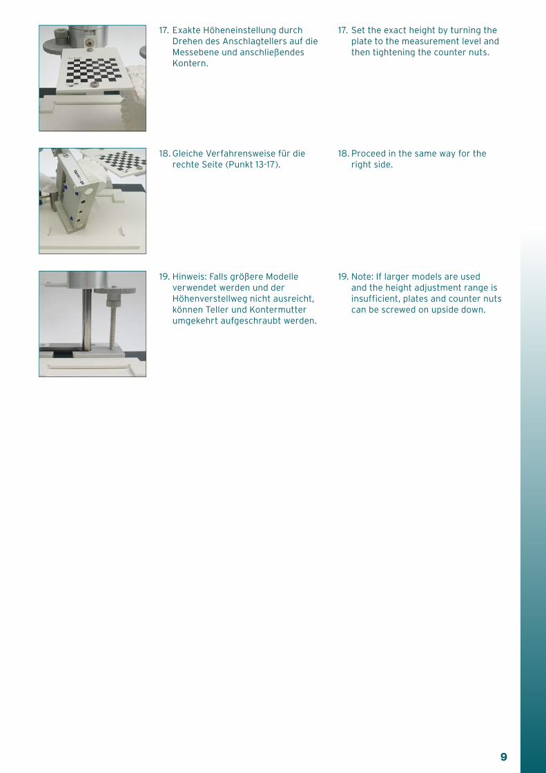
18. Gleiche Verfahrensweise für die rechte Seite (Punkt 13-17).
19. Hinweis: Falls größere Modelle verwendet werden und der Höhenverstellweg nicht ausreicht, können Teller und Kontermutter umgekehrt aufgeschraubt werden.
17. Exakte Höheneinstellung durch Drehen des Anschlagtellers auf die Messebene und anschließendes Kontern.
17. Set the exact height by turning the plate to the measurement level and then tightening the counter nuts.
18. Proceed in the same way for the right side.
19. Note: If larger models are used and the height adjustment range is insufficient, plates and counter nuts can be screwed on upside down.

10
Verwendung des CA® CHECKER in Verbindung mit dem Erweiterungsset (4.0) für CA® Fotostativ
Using the CA® CHECKER in combination with the expansion set (4.0) for CA® photo support
Damit die Messwerte (Angulation und Torque) mit dem CA® CHECKER vor und nach dem Set-Up präzise ermittelt werden können, muss der CA® Modellhalter des Erweiterungssets plan auf dem Modellstativ aufliegen. Dazu folgende Schritte beachten:
1. Die Köpfe der blauen Hülsen mit einem Skalpell glatt an der Metallbasis abschneiden.
2. Kontrolle auf dem Modellstativ.
3. Richtige Handhabung des CA® Modellhalters auf dem
Modellstativ während der Messung.
In order to precisely determine the measurement values (angulation and torque) with the CA® CHECKER before and after set-up, you must ensure that the CA® model holder of the expansion set lies flat on the model support. To do this, take the following steps:
1. Cut off the heads of the blue sleeves flush with the metal base using a scalpel.
2. Carry out a check on the model support.
3. Take care to handle the CA® model holder on the model support correctly during measurement.

11
Notizen

SCHEU-DENTAL GmbHwww.scheu-dental.com
phone +49 2374 9288-0fax +49 2374 9288-90
Am Burgberg 2058642 Iserlohn · Germany
DE
/GB
1.0
00/0
5/16
G R
EF
PM
0141
.01