experimental investigation into the edm process of...
TRANSCRIPT
Turkish J Eng Env Sci
(2014) 38: 231 – 239
c⃝ TUBITAK
doi:10.3906/muh-1404-15
Turkish Journal of Engineering & Environmental Sciences
http :// journa l s . tub i tak .gov . t r/eng ineer ing/
Research Article
Experimental investigation into the EDM process of γ -TiAl
Mohammadreza SHABGARD1,∗, Hossein FARAJI1, Behnam KHOSROZADEH1,Keivan AMINI2, Mirsadegh SEYEDZAVVAR1
1Department of Manufacturing, Faculty of Mechanical Engineering, University of Tabriz,Tabriz, Iran
2Department of Mechanical, Automotive, and Materials Engineering, University of Windsor, Windsor,Ontario, Canada
Received: 29.04.2014 • Accepted/Published Online: 03.01.2015 • Printed: 30.06.2015
Abstract: Among the advanced materials, the γ -TiAl intermetallic compounds, due to their unique properties, are
being gradually employed instead of nickel base super alloys, titanium alloys, and other high temperature alloys in the
aerospace and automotive industries. These properties include maintaining high strength and creep resistance at elevated
temperatures. Considering the features of this material and the limitations of traditional machining procedures, in this
paper the results of utilizing the EDM process for γ -TiAl and the effects of input parameters, including discharge current
and discharge duration, on output characteristics, comprising material removal rate, tool wear ratio, surface texture, and
compositions and phases of machined surfaces, are presented. The results show that the EDM process affects surface
integrity of γ -TiAl and causes the formation of surface cracks even at the lowest level of discharged energy. The increase
in the discharge energy results in the formation of longer cracks with wider mouths. Due to the ingress of carbon and
oxygen on the surface of the specimen, initial compositions and phases of machined surfaces are changed and brittle
phases such as Ti3Al and TiC are formed on the machined surfaces.
Key words: EDM, γ -TiAl, material removal rate, tool wear rate, Ra, X-ray diffraction method, EDS, scanning electron
microscopy
1. Introduction
TiAl alloys exhibit a high capability to be employed instead of some super alloys such as nickel-based alloys for
applications at high temperatures. Retention of strength at elevated temperatures, low tendency of absorption of
hydrogen, and good creep resistance make this material a viable choice in the aircraft and automotive industries
[1].
However, manufacturing parts made of γ -TiAl compounds are classified as difficult-to-machine materials
[2]. Several studies have been conducted to explore the machining features of this material. Weinert et al. [3]
investigated drilling, tapping, milling, and boring processes in the manufacturing of a connecting-rod made of
γ -TiAl utilized in auto engines. They reported that because of the high hardness of γ -TiAl alloys, cemented
carbide or harder cutters such as the ones made of cubic boron nitride and polycrystalline diamond are just
applicable in the machining process of this material. Aspinwall et al. [4] conducted a comprehensive study of
machining methods of γ -TiAl and reported that turning and drilling processes lead to surface integrity problems
and creation of a high density of cracks on the machined surfaces. Sarkar et al. [5–8] studied wire EDM of
γ -TiAl and optimized the process by parametric analysis. They also modeled processes to predict output
∗Correspondence: [email protected]
231
SHABGARD et al./Turkish J Eng Env Sci
characteristics of processes. Their results showed that γ -TiAl is readily machinable by wire electrical discharge
machining. Hascalık and Caydas [9] conducted experimental research on the electrical discharge machining of
Ti-6Al-4V alloy with different tool electrodes and reported that material removal rate (MRR), tool wear, surface
roughness, and recast layer thickness increased with the increase of discharge current and discharge duration.
Wang et al. [10] investigated the influences of dielectric (compound dielectric, distilled water, and kerosene)
characteristics on EDM of titanium alloy. The experimental findings demonstrated that titanium alloy EDM
in compound dielectrics achieved the highest MRR, a lower relative electrode wear ratio than that in kerosene,
and fewer microcracks than in distilled water.
Chen et al. [11] machined Ti-6Al-4V alloy with two different dielectrics (distilled water and kerosene).
Their findings indicated that the MRR is lower and the tool wear ration (TWR) is greater in kerosene. Lin et
al. [12], by adding an electrical discharge system to an ultrasonic machine, were able to increase the MRR in
ultrasonic machining of Ti-6Al-4V alloy. They also used abrasive particles in dielectric fluid. Their work showed
that the recast layer thickness when using ultrasonic vibrations in distilled water is lower than in conventional
EDM.
Gu et al. [13] studied electrical discharge machining of Ti-6Al-4V using bundled pipes as an electrode,
through which high pressure dielectric fluid was pumped. The results showed that using this washing method
increases MRR while decreasing TWR.
In this study, the machining of a γ -TiAl compound is conducted by die-sinking electrical-discharge
method to investigate the effects of input parameters of the EDM process, comprising discharge current
and discharge duration, on output characteristics, including MRR, TWR, surface roughness and topography,
constructed compounds, and phases on the surfaces of machined work pieces.
2. Experimental setup
2.1. Material and experimental instruments
In order to prepare base material, titanium ingots with purity of 99.8% and aluminum ingots with purity of
99.5%, each with given weight percentages, were melted in a vacuum melting furnace and caste to produce
Ti-53Al intermetallic compound ingots. To eliminate defects in the casting process such as microsegregation, a
homogenizing heat treatment process was performed at a temperature below 1100 ◦C for 48 h. Samples were
then cut with a cross-section of 11 ×11 mm2 and a height of 9 mm from prepared ingots using a wire EDM.
The specimens were then ground using sandpapers to obtain similar surface roughness on all of them. These
samples were used in machining experiments. Copper electrodes with dimensions of Ø 18 mm × 40 mm were
used as tool electrodes in machining processes. Some mechanical and physical properties of the γ -TiAl are
listed in Table 1.
Table 1. Mechanical and physical properties of γ -TiAl [4,5].
Properties ValueYield strength (MPa) 463Ultimate tensile strength (MPa) 499Modulus of elasticity (GPa) 144Elongation (%) 0.55Poisson’s ratio 0.24Density (g/mm3) 3.81Thermal conductivity (W/mK) ∼ 22
232
SHABGARD et al./Turkish J Eng Env Sci
A CHARMILLES ROBOFORM 200 CNC die-sinking electric-discharge machine, equipped with an
isopulse generator, was employed to perform the experiments. Oil flux-ELF2 was used as a dielectric fluid.
To measure the mass differences of electrodes before and after the EDM process, a CP224S-Surtorius digital
balance with readability of 0.0001 g was utilized. A Mahr-Perthomether M2 apparatus was employed to measure
surface roughness of EDMed electrodes. Current and voltage variations of the gap during the EDM process were
measured using PC-based digital storage oscilloscopes (TNM ELECTRONICS-DS20080A Oscilloscope Card).
Chemical compositional analyses of machined work pieces were performed using X-ray diffraction method
(XRD) and surface topology observations were conducted by scanning electron microscopy (SEM).
2.2. Process variables and design of experiments
To investigate the machinability of γ -TiAl, two main parameters of the EDM process, including discharge
current (I) in five levels and discharge duration (Ton) in four levels, were considered to be the input variables.
A full factorial design was chosen for the experiments. Different levels of input parameters and other constants
of machining condition during experimentations are listed in Table 2. Eqs. (1) and (2) were employed to
calculate MRR and %TWR:
MRR = (∆mW.P./(t× ρW.P.))× 1000, (1)
%TWR = ((∆mT. × ρW.P.)/(∆mW.P. × ρT.))× 100, (2)
where MRR is material removal rate, %TWR is tool wear ratio, ∆mW.P. is weight difference of the work piece
after EDM, ∆mT. is the weight difference of the tool after EDM, ρW.P. is the density of the work piece, ρT. is
the density of tool, and t is the machining period.
Table 2. Experiment conditions and variables of process.
Conditions and variables DescriptionDischarge current (A) 3, 6, 12, 24, 64Discharge duration (µs) 6.4, 25, 50, 100Pulse off time (µs) 25Open circuit voltage (V) 120Type of generator IsopulseTool polarity PositiveDielectric fluid and flushing method Oil Flux ELF2, submerged and side flushing simultaneously
3. Results and discussion
3.1. The effects of discharge current and discharge duration on MRR
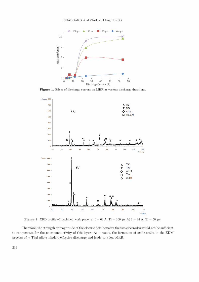
Figure 1 illustrates the effects of discharge current and discharge duration on MRR. As shown, at low discharge
current the MRR is very low for all of the discharge durations. The explanation for this is that, as shown in
Figure 2, due to the poor oxidation resistance of γ -TiAl alloys at elevated temperatures (above 700 ◦C), we
have the formation of constitutive elements’ oxides such as rutile-titania (TiO2) and α -alumina (Al2O3) on
the surface of the machining work piece [14–17]. The formation of the oxide scales on the surface of machining
work pieces forms an effective barrier layer with a high electrical resistance on the surface.
233
SHABGARD et al./Turkish J Eng Env Sci
0
5
10
15
20
0 10 20 30 40 50 60 70
MR
R (
mm
3/m
in)
Discharge Current (A)
100 µs 50 µs 25 µs 6.4 µs
Figure 1. Effect of discharge current on MRR at various discharge durations.
Figure 2. XRD profile of machined work piece: a) I = 64 A, Ti = 100 µs; b) I = 24 A, Ti = 50 µs.
Therefore, the strength or magnitude of the electric field between the two electrodes would not be sufficient
to compensate for the poor conductivity of this layer. As a result, the formation of oxide scales in the EDM
process of γ -TiAl alloys hinders effective discharge and leads to a low MRR.
234
SHABGARD et al./Turkish J Eng Env Sci
Moreover, Figure 1 shows that the increase in discharge current leads to the increase in MRR. The
justification is that when discharge current increases, the density of discharge grows over a certain amount,
which leads to an increase in MRR with a sharp gradient in MRR-I curve. The correlation between the
discharge energy and discharge current is illustrated in Eq. (3). According to Eq. (3), increase in discharge
current leads to increase in discharge energy. The formation of oxidation products on the surface of γ -TiAl
alloys is dependent upon the kinetics of the process and the best deposition rates occur around the temperature
of 1000 ◦C [17]. The increase in discharge power intensifies the heat generated during each discharge, which
prevents the formation and deposition of oxide scales on the machining surface of the work piece, and therefore
the MRR increases. This is clear from XRD results represented in Figure 2a (high energy) and 2b (low energy)
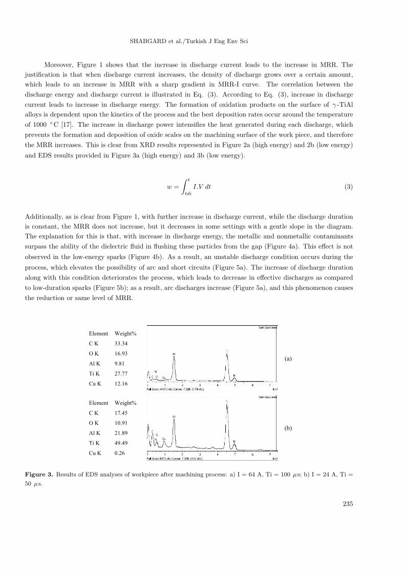
and EDS results provided in Figure 3a (high energy) and 3b (low energy).
w =
∫ t
tdi
I.V dt (3)
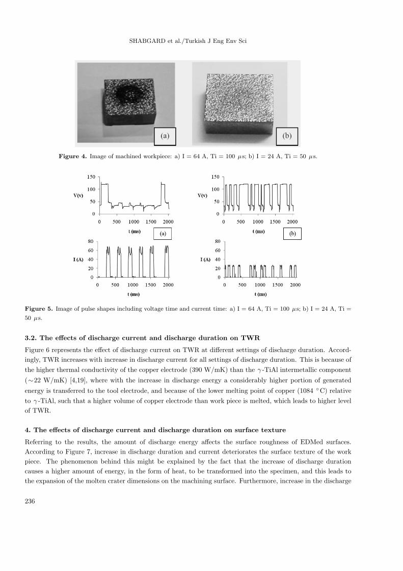
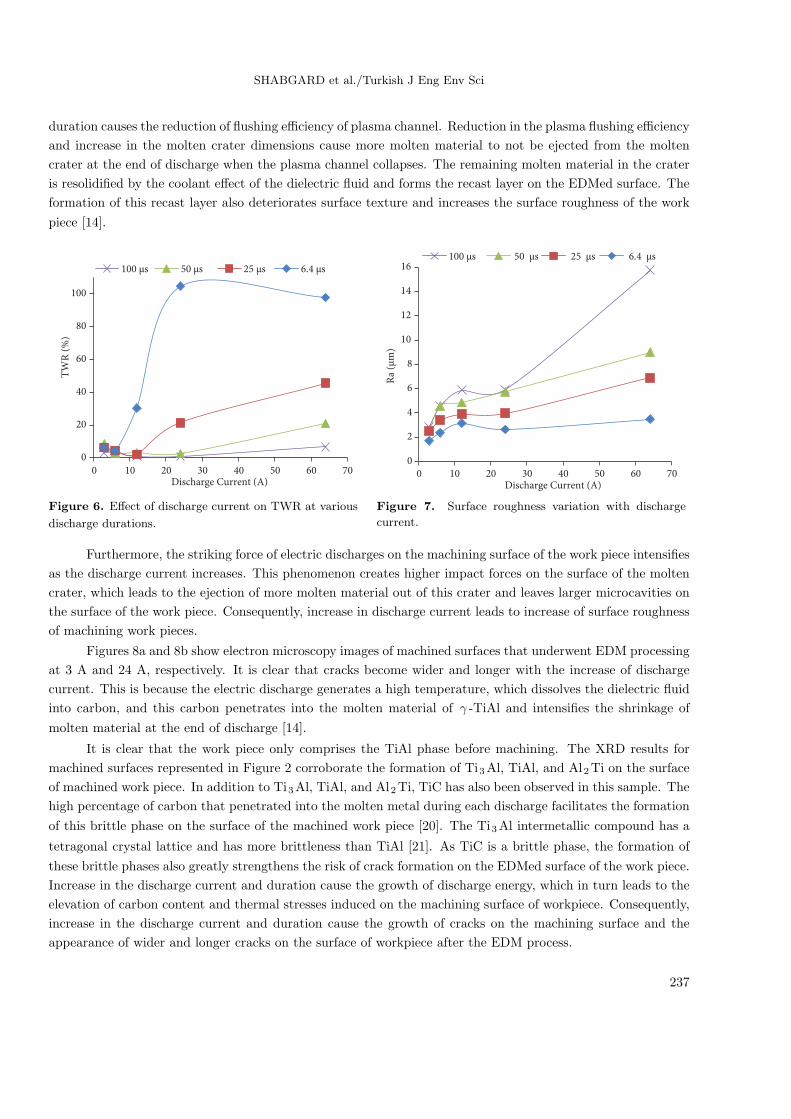
Additionally, as is clear from Figure 1, with further increase in discharge current, while the discharge duration
is constant, the MRR does not increase, but it decreases in some settings with a gentle slope in the diagram.
The explanation for this is that, with increase in discharge energy, the metallic and nonmetallic contaminants
surpass the ability of the dielectric fluid in flushing these particles from the gap (Figure 4a). This effect is not
observed in the low-energy sparks (Figure 4b). As a result, an unstable discharge condition occurs during the
process, which elevates the possibility of arc and short circuits (Figure 5a). The increase of discharge duration
along with this condition deteriorates the process, which leads to decrease in effective discharges as compared
to low-duration sparks (Figure 5b); as a result, arc discharges increase (Figure 5a), and this phenomenon causes
the reduction or same level of MRR.
(a)
Element Weight%
C K 33.34
O K 16.93
Al K 9.81
Ti K 27.77
Cu K 12.16
(b)
Element Weight%
C K 17.45
O K 10.91
Al K 21.89
Ti K 49.49
Cu K 0.26
Figure 3. Results of EDS analyses of workpiece after machining process: a) I = 64 A, Ti = 100 µs; b) I = 24 A, Ti =
50 µs.
235
SHABGARD et al./Turkish J Eng Env Sci
Figure 4. Image of machined workpiece: a) I = 64 A, Ti = 100 µs; b) I = 24 A, Ti = 50 µs.
Figure 5. Image of pulse shapes including voltage time and current time: a) I = 64 A, Ti = 100 µs; b) I = 24 A, Ti =
50 µs.
3.2. The effects of discharge current and discharge duration on TWR
Figure 6 represents the effect of discharge current on TWR at different settings of discharge duration. Accord-
ingly, TWR increases with increase in discharge current for all settings of discharge duration. This is because of
the higher thermal conductivity of the copper electrode (390 W/mK) than the γ -TiAl intermetallic component
(∼22 W/mK) [4,19], where with the increase in discharge energy a considerably higher portion of generated
energy is transferred to the tool electrode, and because of the lower melting point of copper (1084 ◦C) relative
to γ -TiAl, such that a higher volume of copper electrode than work piece is melted, which leads to higher level
of TWR.
4. The effects of discharge current and discharge duration on surface texture
Referring to the results, the amount of discharge energy affects the surface roughness of EDMed surfaces.
According to Figure 7, increase in discharge duration and current deteriorates the surface texture of the work
piece. The phenomenon behind this might be explained by the fact that the increase of discharge duration
causes a higher amount of energy, in the form of heat, to be transformed into the specimen, and this leads to
the expansion of the molten crater dimensions on the machining surface. Furthermore, increase in the discharge
236
SHABGARD et al./Turkish J Eng Env Sci
duration causes the reduction of flushing efficiency of plasma channel. Reduction in the plasma flushing efficiency
and increase in the molten crater dimensions cause more molten material to not be ejected from the molten
crater at the end of discharge when the plasma channel collapses. The remaining molten material in the crater
is resolidified by the coolant effect of the dielectric fluid and forms the recast layer on the EDMed surface. The
formation of this recast layer also deteriorates surface texture and increases the surface roughness of the work
piece [14].
0
20
40
60
80
100
0 10 20 30 40 50 60 70
TW
R (
%)
Discharge Current (A)
100 µs 50 µs 25 µs 6.4 µs
0
2
4
6
8
10
12
14
16
0 10 20 30 40 50 60 70
Ra
(µm
)
Discharge Current (A)
100 µs 50 µs 25 µs 6.4 µs
Figure 6. Effect of discharge current on TWR at various
discharge durations.
Figure 7. Surface roughness variation with discharge
current.
Furthermore, the striking force of electric discharges on the machining surface of the work piece intensifies
as the discharge current increases. This phenomenon creates higher impact forces on the surface of the molten
crater, which leads to the ejection of more molten material out of this crater and leaves larger microcavities on
the surface of the work piece. Consequently, increase in discharge current leads to increase of surface roughness
of machining work pieces.
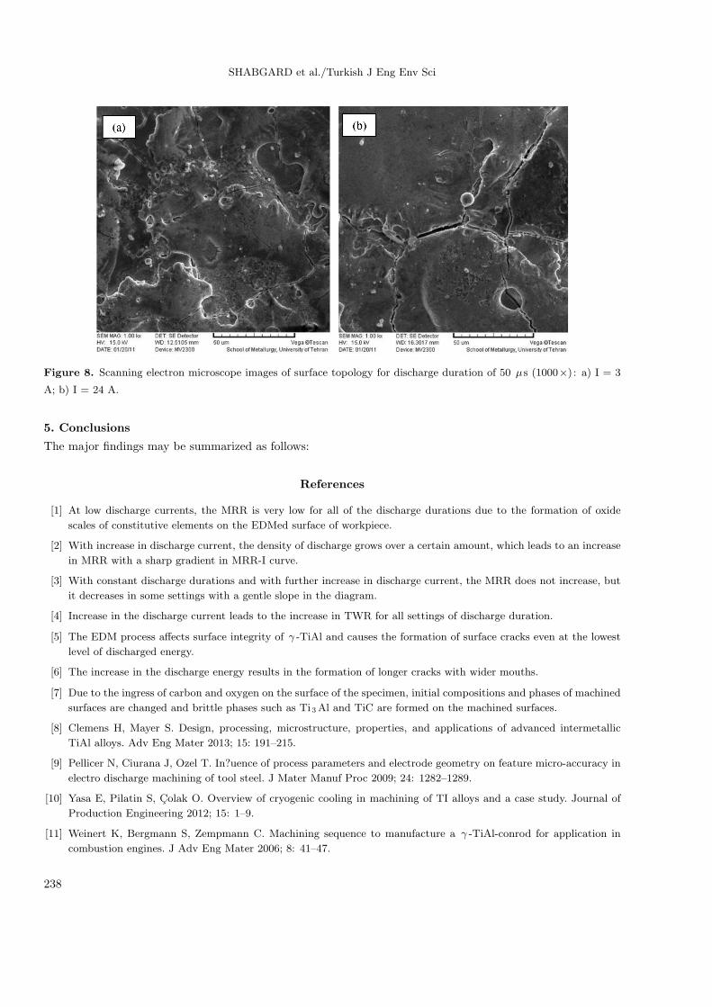
Figures 8a and 8b show electron microscopy images of machined surfaces that underwent EDM processing
at 3 A and 24 A, respectively. It is clear that cracks become wider and longer with the increase of discharge
current. This is because the electric discharge generates a high temperature, which dissolves the dielectric fluid
into carbon, and this carbon penetrates into the molten material of γ -TiAl and intensifies the shrinkage of
molten material at the end of discharge [14].
It is clear that the work piece only comprises the TiAl phase before machining. The XRD results for
machined surfaces represented in Figure 2 corroborate the formation of Ti3Al, TiAl, and Al2Ti on the surface
of machined work piece. In addition to Ti3Al, TiAl, and Al2Ti, TiC has also been observed in this sample. The
high percentage of carbon that penetrated into the molten metal during each discharge facilitates the formation
of this brittle phase on the surface of the machined work piece [20]. The Ti3Al intermetallic compound has a
tetragonal crystal lattice and has more brittleness than TiAl [21]. As TiC is a brittle phase, the formation of
these brittle phases also greatly strengthens the risk of crack formation on the EDMed surface of the work piece.
Increase in the discharge current and duration cause the growth of discharge energy, which in turn leads to the
elevation of carbon content and thermal stresses induced on the machining surface of workpiece. Consequently,
increase in the discharge current and duration cause the growth of cracks on the machining surface and the
appearance of wider and longer cracks on the surface of workpiece after the EDM process.
237
SHABGARD et al./Turkish J Eng Env Sci
Figure 8. Scanning electron microscope images of surface topology for discharge duration of 50 µs (1000×) : a) I = 3
A; b) I = 24 A.
5. Conclusions
The major findings may be summarized as follows:
References
[1] At low discharge currents, the MRR is very low for all of the discharge durations due to the formation of oxide
scales of constitutive elements on the EDMed surface of workpiece.
[2] With increase in discharge current, the density of discharge grows over a certain amount, which leads to an increase
in MRR with a sharp gradient in MRR-I curve.
[3] With constant discharge durations and with further increase in discharge current, the MRR does not increase, but
it decreases in some settings with a gentle slope in the diagram.
[4] Increase in the discharge current leads to the increase in TWR for all settings of discharge duration.
[5] The EDM process affects surface integrity of γ -TiAl and causes the formation of surface cracks even at the lowest
level of discharged energy.
[6] The increase in the discharge energy results in the formation of longer cracks with wider mouths.
[7] Due to the ingress of carbon and oxygen on the surface of the specimen, initial compositions and phases of machined
surfaces are changed and brittle phases such as Ti3Al and TiC are formed on the machined surfaces.
[8] Clemens H, Mayer S. Design, processing, microstructure, properties, and applications of advanced intermetallic
TiAl alloys. Adv Eng Mater 2013; 15: 191–215.
[9] Pellicer N, Ciurana J, Ozel T. In?uence of process parameters and electrode geometry on feature micro-accuracy in
electro discharge machining of tool steel. J Mater Manuf Proc 2009; 24: 1282–1289.
[10] Yasa E, Pilatin S, Colak O. Overview of cryogenic cooling in machining of TI alloys and a case study. Journal of
Production Engineering 2012; 15: 1–9.
[11] Weinert K, Bergmann S, Zempmann C. Machining sequence to manufacture a γ -TiAl-conrod for application in
combustion engines. J Adv Eng Mater 2006; 8: 41–47.
238
SHABGARD et al./Turkish J Eng Env Sci
[12] Aspinwall DK, Dewes RC, Mantle AL. The machining of γ -TiAl intermetallic alloys. CIRP Ann-Manuf Techn 2005;
5: 99–104.
[13] Sarkar S, Mitra S, Bhattacharyya B. Parametric analysis and optimization of wire electrical discharge machining
of γ -titanium aluminide alloy. J Mater Proc Tech 2005; 159: 286–294.
[14] Sarkar S, Mitra S, Bhattacharyya B. Parametric optimization of wire electrical discharge machining of γ titanium
aluminide alloy through an artificial neural network model. Int J Adv Manuf Tech 2006; 27: 501–508.
[15] Sarkar S, Sekh M, Mitra S, Bhattacharyya B. Modeling and optimization of wire electrical discharge machining of
γ -TiAl in trim cutting operation. J Mater Proc Tech 2008; 205: 376–387.
[16] Hascalık A, Caydas U. Electrical discharge machining of titanium alloy (Ti–6Al–4V). Appl Surf Sci 2007; 253:
9007–9016.
[17] Wang X, Liu Z, Xue R, Tian Z, Huang Y. Research on the influence of dielectric characteristics on the EDM of
titanium alloy. Int J Adv Manuf Tech 2014; 72: 979–987.
[18] Chen S, Yan B, Huang F. Influence of kerosene and distilled water as dielectrics on the electric discharge machining
characteristics of Ti–6A1–4V. J Mater Process Tech 1999; 87: 107–111.
[19] Lin YC, Yan BH, Chang YS. Machining characteristics of titanium alloy (Ti–6Al–4V) using a combination process
of EDM with USM. J Mater Process Tech 2000; 104: 171–177.
[20] Gu L, Lei L, Zhao W, Rajurkar KP. Electrical discharge machining of Ti6Al4V with a bundled electrode. Int J
Mach Tool Manu 2012; 53: 100–106.
[21] Lee HT, Tai TY. Relationship between EDM parameters and surface crack formation. J Mater Proc Tech 2003;
142: 676–683.
[22] Mu-Rong Y, Shyi-Kaan W. Oxidation resistance improvement of TiAl intermetallics using surface modification.
Bull Col Eng NTU 2003; 89: 3–19.
[23] Min-Sheng C, Shyi-Kaan W. Interrelations of TiAl3 thin film on bulk γ -TiAl and on bulk α2 -Ti3Al alloys at
700–1000◦C. Japan Ins Metal Mater Tran 2004; 45: 1290–1298.
[24] Thomas M, Bacos MP. Processing and characterization of TiAl based alloys: towards an industrial scale. J Aero
Lab 2011; 3: 1–11.
[25] Ruberto C. Metastable alumina from theory: bulk, surface, and growth of γ -Al2O3 . PhD, Chalmers University of
Technology and Goteborg University, Goteborg, Sweden, 2001.
[26] Lide DR. CRC Handbook of Chemistry and Physics. 90th Edition, CD-ROM Version 2010. Boca Raton, FL, USA:
CRC Press.
[27] Ojha K, Garg RK, Singh KK. MRR improvement in sinking electrical discharge machining: a review. J Miner Mater
Charac Eng 2010; 9: 709–739.
[28] Lapin J. TiAl-based alloys: present status and future perspectives. In: 18th International Conference on Metallurgy
and Metals; Hradec nad Moravicı, Czech Republic. Ostrava, Czech Reublic: Tanger, 2009. pp. 1–12.
239