gelötete plattenwärmetauscher brazed plate heat exchangers ... · gelötete plattenwärmetauscher...
TRANSCRIPT
DEF
5.8
04.4
/04.
11
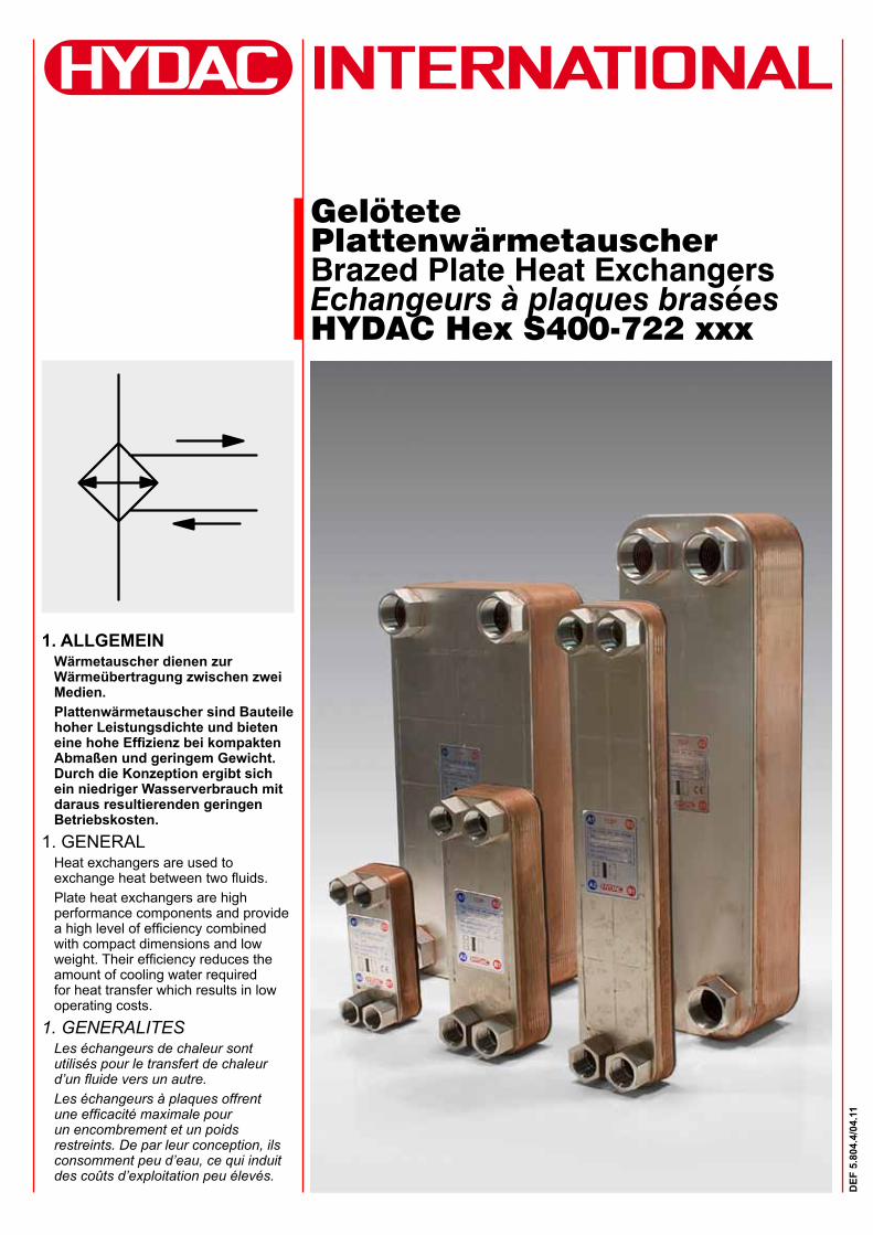
Gelötete PlattenwärmetauscherBrazed Plate Heat ExchangersEchangeurs à plaques braséesHYDAC Hex S400-722 xxx
1. ALLGEMEINWärmetauscher dienen zur Wärmeübertragung zwischen zwei Medien.Plattenwärmetauscher sind Bauteile hoher Leistungsdichte und bieten eine hohe Effizienz bei kompakten Abmaßen und geringem Gewicht. Durch die Konzeption ergibt sich ein niedriger Wasserverbrauch mit daraus resultierenden geringen Betriebskosten.
1. GENERALHeat exchangers are used to exchange heat between two fluids.Plate heat exchangers are high performance components and provide a high level of efficiency combined with compact dimensions and low weight. Their efficiency reduces the amount of cooling water required for heat transfer which results in low operating costs.
1. GENERALITESLes échangeurs de chaleur sont utilisés pour le transfert de chaleur d’un fluide vers un autre.Les échangeurs à plaques offrent une efficacité maximale pour un encombrement et un poids restreints. De par leur conception, ils consomment peu d’eau, ce qui induit des coûts d’exploitation peu élevés.
2
DEF
5.8
04.4
/04.
11
HYDAC HEX S400 –10 –00/G ¾"
BaugrößeSize TailleHYDAC HEX S400 HYDAC HEX S610 HYDAC HEX S615 HYDAC HEX S522 HYDAC HEX S722PlattenanzahlNumber of plates Nombre de plaques
10 14 20 30 40 50 60 70 80 90 100 120 150 190HYDAC HEX S400 l l l l l
HYDAC HEX S610 l l l l l l l l l
HYDAC HEX S615 l l l l l l l l l
HYDAC HEX S722 l l l l l l l l l l l l
HYDAC HEX S522 l l l l l l l l l l l l
Anschlüsse (Standard)HYDAC HEX S400: 4 x G ¾" InnengewindeHYDAC HEX S610 und HYDAC HEX S615: 4 x G1" InnengewindeHYDAC HEX S722: 4 x G 1 ½" InnengewindeHYDAC HEX S522: 4 x G1 ½" InnengewindeOptional sind auch Außengewinde, Löt- und SAE-Anschlüsse möglich.Die Rohrleitungen sind so anzubringen, dass die Anschlüsse spannungsfrei gehalten werden. Längenausdehnungen und Vibrationen aus den Rohrleitungen auf den Wärmetauscher sind zu vermeiden.Connections (standard) HYDAC HEX S400: 4 x G ¾" female threadHYDAC HEX S610 und HYDAC HEX S615: 4 x G1" female threadHYDAC HEX S722: 4 x G 1 ½" female threadHYDAC HEX S522: 4 x G1 ½" female threadMale threaded, soldered and SAE connections are also available as options.Pipes must be connected so that the connections are stress-free. Linear expansion and vibrations from the pipes to the heat exchanger must be avoided.Raccords (standard) HYDAC HEX S400: 4 x G ¾" taraudageHYDAC HEX S610 und HYDAC HEX S615: 4 x G 1" taraudageHYDAC HEX S722: 4 x G 1 1/2" taraudageHYDAC HEX S522: 4 x G1 ½" taraudageDes filetages, des raccords brasés et SAE sont également possibles en option.Eviter les tensions mécaniques et la transmission de vibrations sur les raccords des échangeurs à plaques (dilatation des conduites).
2. TYPENSCHLÜSSEL/ MODEL CODE/ CODE DE COMMANDE1.1 PRODUKTMERKMALE
Wärmeübertragungsplatten und Anschlüsse aus Edelstahl 1.4401 (AISI 316), mit Kupfer vakuum-verlötet. Die Kanten sind geglättet und die Endplatte ist mit einem Kantenschutz versehen. Die spezielle Prägung der Platten sorgt für eine hohe mechanische Festigkeit des Plattenwärmetauschers und erzeugt zudem eine turbulente Strömung, die für eine optimale Wärmeübertragung notwendig ist. Darüber hinaus bewirkt die Strömung einen Selbstreinigungseffekt, da durch die hohen Wandreibungen der Aufbau von Ablagerungen an der Oberfläche verringert wird.
1.1 FEATURESPlates and connections are manufactured from stainless steel to 1.4401 (AISI 316), vacuum-brazed with copper. The plates have smoothed edges and the end plate is provided with edge protection. The special moulding of the plates produces the turbulent flow necessary for effective heat transfer and provides the plate heat exchanger with a high level of mechanical strength. The turbulent flow of the medium also has a self-cleaning action: fluids passing through the narrow channels induce highly turbulent flow at the walls. This results in a scrubbing action reducing contamination on the surfaces.
1.1 CARACTERISTIQUES DU PRODUITPlaques et raccords en acier inoxydable haute résistance 1.4401 (AISI 316), brasés sous vide au cuivre. L'estampage spécial des plaques engendre un flux turbulent, nécessaire pour une transmission optimale de la chaleur et apporte une résistance mécanique élevée des échangeurs à plaques. En outre, le flux génère un effet auto-nettoyant, car la constitution de dépôt sur la surface est minimisée par les nombreux frottements sur les parois.
1.2 ANWENDUNGSBEREICHKühlkreisläufe im Gegenstrom, die mit Wasser, Kühlflüssigkeit, HFC-Druckflüssigkeit oder Öl betrieben werden. Typische Anwendungen sind:
l Werkzeugmaschinenl Pressenl Spritzgießmaschinenl Motorenl Prüfständel Generatoren
1.2 APPLICATIONSCooling circuits in reverse flow using water, coolants, HFC operating fluids or oil. Typical applications are:
l Machine toolsl Pressesl Plastic injection moulding machinesl Enginesl Test rigsl Generators
1.2 DOMAINES D’UTILISATIONTout circuit de refroidissement utilisant de l’eau, du liquide de refroidissement (mélange eau/glycol), de l’HFC ou de l’huile. Les applications typiques sont:
l machines outilsl pressesl machines à injecterl moteursl bancs d’essail générateurs
3
DEF
5.8
04.4
/04.
11
3. BETRIEBSDATENMedium:
l Wasser-Glykol (Kühlflüssigkeit)l HFC-Druckflüssigkeitl Wasserl Öle
Verschmutzung: Der Gehalt an suspendierten Feststoffen sollte unter 10 mg/l liegen. Partikelgröße < 0,6 mm (kugelförmig) Fadenförmige Feststoffe führen schnell zur Erhöhung der Druckverluste.Temperaturbereich: bis 200 °C (Gefrierpunkt und Siedepunkt beachten!)Drücke: max. 30 bar Prüfdruck: 45 bar Ausführung mit Nickellot bis 10 bar Betriebsdruck möglich.Wasserqualität:Folgende Ionen sind unter normalen Bedingungen nicht korrosiv: Phosphat, Nitrat, Nitrit, Eisen, Mangan, Natrium, KaliumFolgende Grenzwerte beziehen sich auf kupfergelötete Plattenwärmetauscher und eine Wassertemperatur von max. 60 °C.
0: korrosiv / corrosive / corrosif+: geeignet / suitable / compatible
3. OPERATING DETAILSMedium:
l Water glycol (coolants)l HFC operating fluidsl Waterl Oil
Contamination: The quantity of particles in suspension should be less than 10 mg/l. Particle size < 0.6 mm (spherical). Thread-like particles cause a rapid rise in pressure drops.Temperature range: up to 200 °C (freezing point and boiling point must be taken into consideration!)Pressure: max. 30 bar Test pressure: 45 bar Nickel-brazed designs are available with an operating pressure up to 10 bar.Water quality:The following ions are not corrosive under normal conditions: phosphate, nitrate, nitrite, iron, manganese, sodium and potassiumThe following limits refer to copper-brazed plate heat exchangers and a water temperature of max. 60 °C.
3. CARACTéRISTIQUES DE FONCTIONNEMENTFluide:
l Mélange eau/glycol (liquide de refroidissement)
l Fluide hydraulique de type HFCl Eaul Huile
Encrassement: La teneur en particules solides en suspension doit être inférieure à 10 mg/l. Taille des particules sphériques < 0,6mm Les polluants filiformes entraînent une augmentation de la perte de charge.Température d’utilisation: jusqu’à 200 °C (Attention aux températures limites des fluides utilisés)Pression: 30 bar max. Pression d’épreuve: 45 bar Exécution avec soudure au nickel jusqu'à une pression de service de 10 bar possible.Qualité de l'eau:Dans des conditions d’utilisation normales, les ions suivants ne sont pas corrosifs: phosphate, nitrate, nitrite, fer, manganèse, sodium, potassium.Les valeurs ci-dessous se réfèrent à des échangeurs à plaques brasées et à une température de 60 °C max.
Wasser-Inhaltsstoffe /Substances dissolved in water / Eléments contenus dans l’eau
Konzentration / Concentration /
Concentration (ppm)
Edelstahl /Stainless steel / Acier inoxydable
Kupfer /Copper / Cuivre
PH-Wert / ph value / PH< 6.0 0 0
6.0 – 9.0 0/+ +> 9.0 + 0
Elektr. Leitfähigkeit /Electrical conductivity /
Conductibilité électr.
< 500 [μ S/cm] + +> 500 [μ S/cm] + 0
Cl- < 50 + +> 50 0 0
SO4-2
< 50 + +50 – 300 + 0
> 300 0 0CaCO3
< 50 + +> 50 0 0
Fe < 0.3 + +> 0.3 + 0
NH3
< 2 + +2 – 20 + 0> 20 + 0
NO3< 100 + +> 100 + 0
S-2 nicht geeignet / not suitable / non compatibleSiO2
< 30 + +NH4
+ < 0.1 + +Freies Chlor / Free chlorine /
Chlore libre< 0.1 + +
CO3-2 < 0.4 + +
4
DEF
5.8
04.4
/04.
11
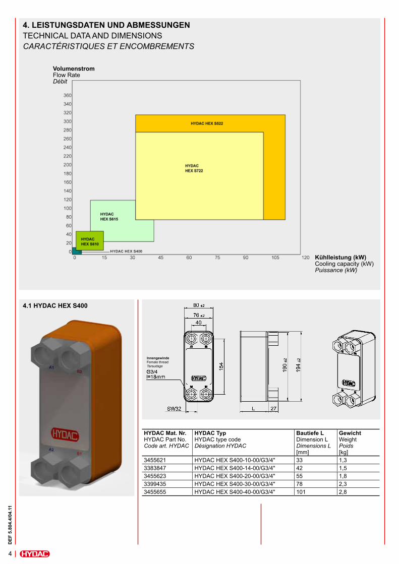
Kühlleistung (kW) Cooling capacity (kW) Puissance (kW)
Volumenstrom Flow Rate Débit
HYDAC Mat. Nr.HYDAC Part No. Code art. HYDAC
HYDAC TypHYDAC type code Désignation HYDAC
Bautiefe LDimension L Dimensions L [mm]
GewichtWeight Poids[kg]
3455621 HYDAC HEX S400-10-00/G3/4" 33 1,33383847 HYDAC HEX S400-14-00/G3/4" 42 1,53455623 HYDAC HEX S400-20-00/G3/4" 55 1,83399435 HYDAC HEX S400-30-00/G3/4" 78 2,33455655 HYDAC HEX S400-40-00/G3/4" 101 2,8
4.1 HYDAC HEX S400
InnengewindeFemale thread Taraudage
4. LEISTUNGSDATEN UND ABMESSUNGENTECHNICAL DATA AND DIMENSIONSCARACTéRISTIQUES ET ENCOMBREMENTS
5
DEF
5.8
04.4
/04.
11
HYDAC Mat. Nr.HYDAC Part No. Code art. HYDAC
HYDAC TypHYDAC type code Désignation HYDAC
Bautiefe LDimension L Dimensions L [mm]
GewichtWeight Poids[kg]
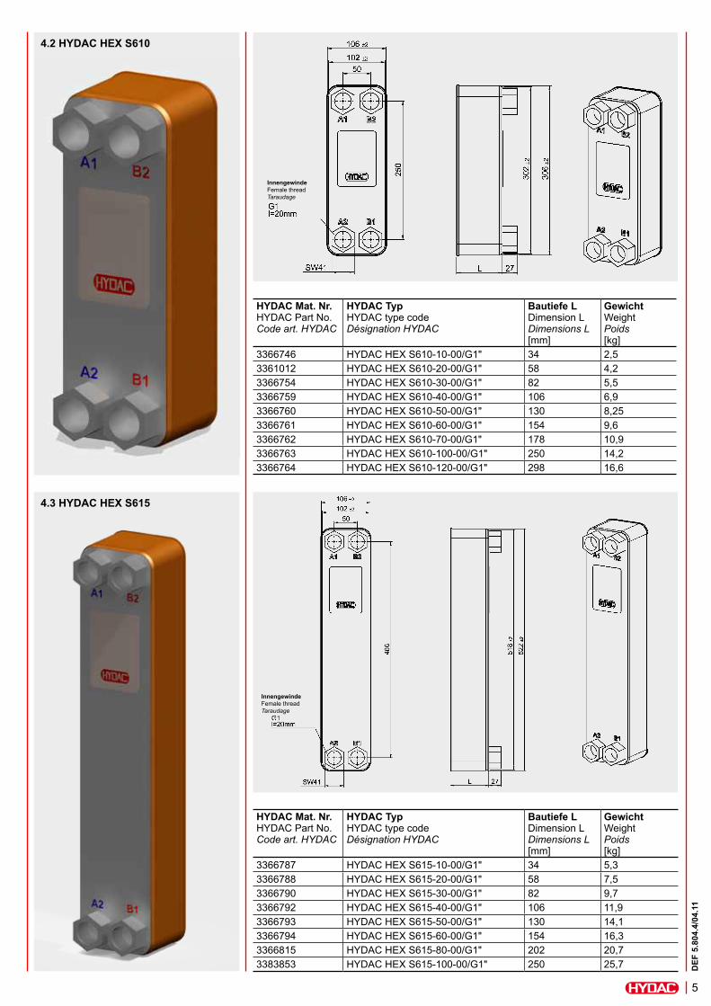
3366746 HYDAC HEX S610-10-00/G1" 34 2,53361012 HYDAC HEX S610-20-00/G1" 58 4,23366754 HYDAC HEX S610-30-00/G1" 82 5,53366759 HYDAC HEX S610-40-00/G1" 106 6,93366760 HYDAC HEX S610-50-00/G1" 130 8,253366761 HYDAC HEX S610-60-00/G1" 154 9,63366762 HYDAC HEX S610-70-00/G1" 178 10,93366763 HYDAC HEX S610-100-00/G1" 250 14,23366764 HYDAC HEX S610-120-00/G1" 298 16,6
4.2 HYDAC HEX S610
4.3 HYDAC HEX S615
InnengewindeFemale thread Taraudage
InnengewindeFemale thread Taraudage
HYDAC Mat. Nr.HYDAC Part No. Code art. HYDAC
HYDAC TypHYDAC type code Désignation HYDAC
Bautiefe LDimension L Dimensions L [mm]
GewichtWeight Poids[kg]
3366787 HYDAC HEX S615-10-00/G1" 34 5,33366788 HYDAC HEX S615-20-00/G1" 58 7,53366790 HYDAC HEX S615-30-00/G1" 82 9,73366792 HYDAC HEX S615-40-00/G1" 106 11,93366793 HYDAC HEX S615-50-00/G1" 130 14,13366794 HYDAC HEX S615-60-00/G1" 154 16,33366815 HYDAC HEX S615-80-00/G1" 202 20,73383853 HYDAC HEX S615-100-00/G1" 250 25,7
6
DEF
5.8
04.4
/04.
11
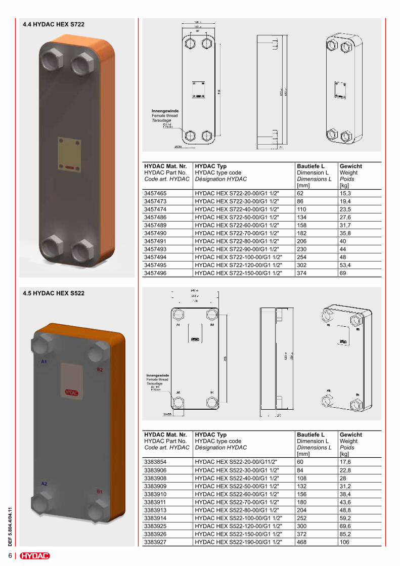
4.5 HYDAC HEX S522
4.4 HYDAC HEX S722
InnengewindeFemale thread Taraudage
InnengewindeFemale thread Taraudage
HYDAC Mat. Nr.HYDAC Part No. Code art. HYDAC
HYDAC TypHYDAC type code Désignation HYDAC
Bautiefe LDimension L Dimensions L [mm]
GewichtWeight Poids[kg]
3383854 HYDAC HEX S522-20-00/G11/2" 60 17,63383906 HYDAC HEX S522-30-00/G1 1/2" 84 22,83383908 HYDAC HEX S522-40-00/G1 1/2" 108 283383909 HYDAC HEX S522-50-00/G1 1/2" 132 31,23383910 HYDAC HEX S522-60-00/G1 1/2" 156 38,43383911 HYDAC HEX S522-70-00/G1 1/2" 180 43,63383913 HYDAC HEX S522-80-00/G1 1/2" 204 48,83383914 HYDAC HEX S522-100-00/G1 1/2" 252 59,23383925 HYDAC HEX S522-120-00/G1 1/2" 300 69,63383926 HYDAC HEX S522-150-00/G1 1/2" 372 85,23383927 HYDAC HEX S522-190-00/G1 1/2" 468 106
HYDAC Mat. Nr.HYDAC Part No. Code art. HYDAC
HYDAC TypHYDAC type code Désignation HYDAC
Bautiefe LDimension L Dimensions L [mm]
GewichtWeight Poids[kg]
3457465 HYDAC HEX S722-20-00/G1 1/2" 62 15,33457473 HYDAC HEX S722-30-00/G1 1/2" 86 19,43457474 HYDAC HEX S722-40-00/G1 1/2" 110 23,53457486 HYDAC HEX S722-50-00/G1 1/2" 134 27,63457489 HYDAC HEX S722-60-00/G1 1/2" 158 31,73457490 HYDAC HEX S722-70-00/G1 1/2" 182 35,83457491 HYDAC HEX S722-80-00/G1 1/2" 206 403457493 HYDAC HEX S722-90-00/G1 1/2" 230 443457494 HYDAC HEX S722-100-00/G1 1/2" 254 483457495 HYDAC HEX S722-120-00/G1 1/2" 302 53,43457496 HYDAC HEX S722-150-00/G1 1/2" 374 69
7
DEF
5.8
04.4
/04.
11
5. ANMERKUNGDie Kühlleistung ist ebenfalls abhängig von der Viskositätsklasse. Bei niedriger Viskositätsklasse erhöht sich die Kühlleistung, bei höherer Viskositätsklasse verringert sich diese. Zur genauen Berechnung sind folgende Daten erforderlich:
lÖltyplzulässige Tanktemperaturlgeforderte Ölaustrittstemperatur
oder erforderliche KühlleistunglWassereintrittstemperatur und max.
WassermengeEine Hilfe hierzu bietet das Auslegungsblatt auf Seite 9.
6. AUSLEGUNGSPROGRAMMEine Auslegung mit abweichenden Betriebsdaten bietet das Auslegungsprogramm. Bei Bedarf wenden Sie sich bitte an die zuständigen Vertriebsorganisationen. Systemvoraussetzungen: Microsoft Windows 95/98/ME/NT/2000/XP/Vista 150 MB Festplattenspeicher 64 MB RAM
5. NOTEThe cooling capacity is also dependent on the viscosity class. At a lower viscosity class the cooling capacity increases, at a higher viscosity class it decreases. In order to make an accurate calculation, the following details are required:
ltype of oillpermitted tank temperaturelrequired outlet temperature of the oil
or necessary cooling capacitylinlet temperature of the water and
max. water quantity.The calculation sheet included on page 9 should help in this process.
6. SELECTION PROGRAMThe cooler selection program calculates the correct heat exchanger in the case of non-standard operating data. Please contact our technical sales department. System requirements: Microsoft Windows 95/98/ME/NT/2000/XP/Vista 150 MB available hard disk memory 64 MB RAM
5. REMARQUELa puissance de refroidissement est directement liée à la viscosité. Lorsque celle-ci est faible, la puissance de refroidissement augmente. De même, lorsque la viscosité est élevée, la puissance diminue. Pour une détermination précise, il convient de préciser:
lType d’huilelTempérature adm. pour le réservoirlTempérature de sortie d’huile de
l’échangeur ou puissance à dissiperlTempérature d’entrée d’eau et débit
d’eau max.Le formulaire de détermination en page 9 fournit une aide à ce sujet.
6. PROGRAMME DE DETERMINATIONSi vos caractéristiques de fonctionnement diffèrent de celles citées précédemment, n’hésitez pas à nous consulter. Grâce à notre programme de détermination, nous vous proposons de définir l’échangeur adapté à vos besoins. Données du système informatique: Microsoft Windows 95/98/ME/NT/2000/XP/Vista 150 MB Capacité disponible du disque dur 64 MB RAM
8
DEF
5.8
04.4
/04.
11
8
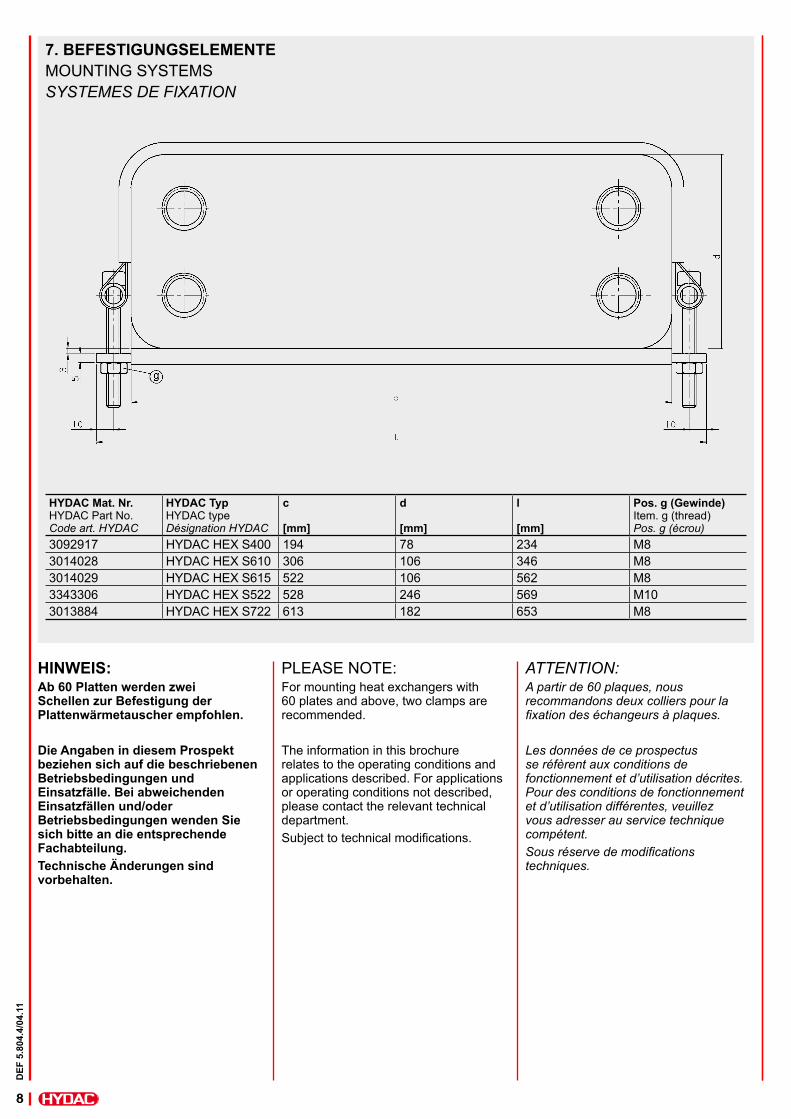
7. BEFESTIGUNGSELEMENTE MOUNTING SYSTEMSSYSTEMES DE FIXATION
HYDAC Mat. Nr.HYDAC Part No. Code art. HYDAC
HYDAC TypHYDAC type Désignation HYDAC
c [mm]
d [mm]
l [mm]
Pos. g (Gewinde) Item. g (thread)Pos. g (écrou)
3092917 HYDAC HEX S400 194 78 234 M83014028 HYDAC HEX S610 306 106 346 M83014029 HYDAC HEX S615 522 106 562 M83343306 HYDAC HEX S522 528 246 569 M103013884 HYDAC HEX S722 613 182 653 M8
ATTENTION:A partir de 60 plaques, nous recommandons deux colliers pour la fixation des échangeurs à plaques.
Les données de ce prospectus se réfèrent aux conditions de fonctionnement et d’utilisation décrites. Pour des conditions de fonctionnement et d’utilisation différentes, veuillez vous adresser au service technique compétent.Sous réserve de modifications techniques.
HINWEIS:Ab 60 Platten werden zwei Schellen zur Befestigung der Plattenwärmetauscher empfohlen.
Die Angaben in diesem Prospekt beziehen sich auf die beschriebenen Betriebsbedingungen und Einsatzfälle. Bei abweichenden Einsatzfällen und/oder Betriebsbedingungen wenden Sie sich bitte an die entsprechende Fachabteilung. Technische Änderungen sind vorbehalten.
PLEASE NOTE:For mounting heat exchangers with 60 plates and above, two clamps are recommended.
The information in this brochure relates to the operating conditions and applications described. For applications or operating conditions not described, please contact the relevant technical department.Subject to technical modifications.
9
DEF
5.8
04.4
/04.
11
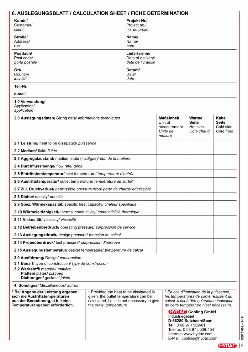
Cooling GmbHIndustriegebiet D-66280 Sulzbach/Saar Tel.: 0 68 97 / 509-01 Telefax: 0 68 97 / 509-454 Internet: www.hydac.com E-Mail: [email protected]
* Bei Angabe der Leistung ergeben sich die Austrittstemperaturen aus der Berechnung, d.h. keine Temperaturangaben erforderlich.
Kunde/Customer/ client
Projekt-Nr./Project no./ no. du projet
Straße/Address/ rue
Name/Name/ nom
Postfach/Post code/ boîte postale
Liefertermin/Date of delivery/ date de livraison
Ort/Country/ localité
Datum/Date/ date
Tel.-Nr.
1.0 Verwendung/Application/ application
2.0 Auslegungsdaten/ Sizing data/ informations techniques MaßeinheitUnit of measurement Unité de mesure
Warme SeiteHot side Côté chaud
Kalte SeiteCold side Côté froid
2.1 Leistung/ heat to be dissipated/ puissance
2.2 Medium/ fluid/ fluide
2.3 Aggregatzustand/ medium state (fluid/gas)/ état de la matière
2.4 Durchflussmenge/ flow rate/ débit
2.5 Eintrittstemtemperatur/ inlet temperature/ température d’entrée
2.6 Austrittstemperatur/ outlet temperature/ température de sortie*
2.7 Zul. Druckverlust/ permissible pressure drop/ perte de charge admissible
2.8 Dichte/ density/ densité
2.9 Spez. Wärmekapazität/ specific heat capacity/ chaleur spécifique
2.10 Wärmeleitfähigkeit/ thermal conductivity/ conductibilité thermique
2.11 Viskosität/ viscosity/ viscosité
2.12 Betriebsüberdruck/ operating pressure/ surpression de service
2.13 Auslegungsdruck/ design pressure/ pression de calcul
2.14 Probeüberdruck/ test pressure/ surpression d’épreuve
2.15 Auslegungstemperatur/ design temperature/ température de calcul
3.0 Ausführung/ Design/ construction3.1 Bauart/ type of construction/ type de construction3.2 Werkstoff/ material/ matière Platten/ plates/ plaques Dichtungen/ gaskets/ joints
4. Sonstiges/ Miscellaneous/ autres* Provided the heat to be dissipated is given, the outlet temperature can be calculated, i.e. it is not necessary to give the outlet temperature
* En cas d’indication de la puissance, les températures de sortie résultent du calcul, c’est à dire qu’aucune indication de cette température n’est nécessaire.
6. AUSLEGUNGSBLATT / CALCULATION SHEET / FICHE DETERMINATION
DEF
5.8
09.1
/11.
09D
EF 5
.809
.1/1
1.09
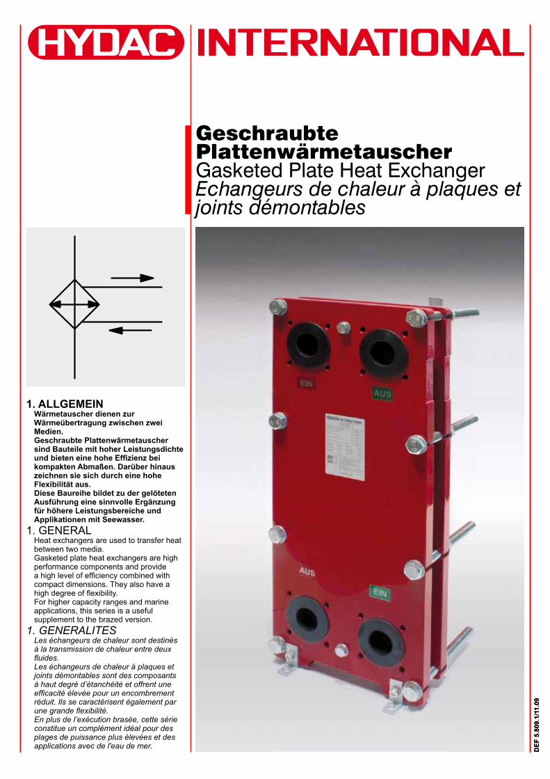
Geschraubte Plattenwärmetauscher Gasketed Plate Heat Exchanger Echangeurs de chaleur à plaques et joints démontables
1. ALLGEMEINWärmetauscher dienen zur Wärmeübertragung zwischen zwei Medien.Geschraubte Plattenwärmetauscher sind Bauteile mit hoher Leistungsdichte und bieten eine hohe Effizienz bei kompakten Abmaßen. Darüber hinaus zeichnen sie sich durch eine hohe Flexibilität aus. Diese Baureihe bildet zu der gelöteten Ausführung eine sinnvolle Ergänzung für höhere Leistungsbereiche und Applikationen mit Seewasser.
1. GENERALHeat exchangers are used to transfer heat between two media.Gasketed plate heat exchangers are high performance components and provide a high level of efficiency combined with compact dimensions. They also have a high degree of flexibility.For higher capacity ranges and marine applications, this series is a useful supplement to the brazed version.
1. GENERALITESLes échangeurs de chaleur sont destinés à la transmission de chaleur entre deux fluides.Les échangeurs de chaleur à plaques et joints démontables sont des composants à haut degré d’étanchéité et offrent une efficacité élevée pour un encombrement réduit. Ils se caractérisent également par une grande flexibilité.En plus de l’exécution brasée, cette série constitue un complément idéal pour des plages de puissance plus élevées et des applications avec de l'eau de mer.
2
DEF
5.8
09.1
/11.
09
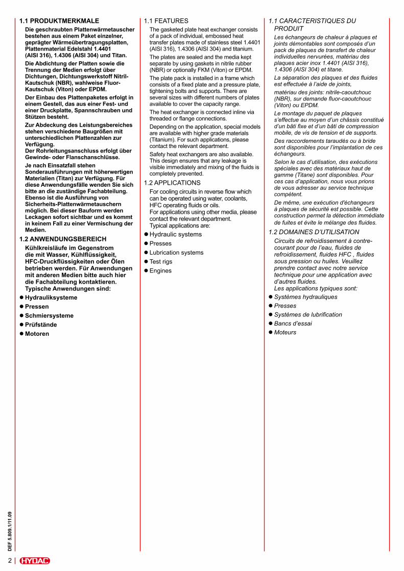
1.1 PRODUKTMERKMALEDie geschraubten Plattenwärmetauscher bestehen aus einem Paket einzelner, geprägter Wärmeübertragungsplatten, Plattenmaterial Edelstahl 1.4401 (AISI 316), 1.4306 (AISI 304) und Titan.Die Abdichtung der Platten sowie die Trennung der Medien erfolgt über Dichtungen, Dichtungswerkstoff Nitril-Kautschuk (NBR), wahlweise Fluor-Kautschuk (Viton) oder EPDM.Der Einbau des Plattenpaketes erfolgt in einem Gestell, das aus einer Fest- und einer Druckplatte, Spannschrauben und Stützen besteht.Zur Abdeckung des Leistungsbereiches stehen verschiedene Baugrößen mit unterschiedlichen Plattenzahlen zur Verfügung. Der Rohrleitungsanschluss erfolgt über Gewinde- oder Flanschanschlüsse.Je nach Einsatzfall stehen Sonderausführungen mit höherwertigen Materialien (Titan) zur Verfügung. Für diese Anwendungsfälle wenden Sie sich bitte an die zuständige Fachabteilung. Ebenso ist die Ausführung von Sicherheits-Plattenwärmetauschern möglich. Bei dieser Bauform werden Leckagen sofort sichtbar und es kommt in keinem Fall zu einer Vermischung der Medien.
1.2 ANWENDUNGSBEREICHKühlkreisläufe im Gegenstrom die mit Wasser, Kühlflüssigkeit, HFC-Druckflüssigkeiten oder Ölen betrieben werden. Für Anwendungen mit anderen Medien bitte auch hier die Fachabteilung kontaktieren. Typische Anwendungen sind:
l Hydrauliksystemel Pressenl Schmiersystemel Prüfständel Motoren
1.1 FEATURESThe gasketed plate heat exchanger consists of a pack of individual, embossed heat transfer plates made of stainless steel 1.4401 (AISI 316), 1.4306 (AISI 304) and titanium.The plates are sealed and the media kept separate by using gaskets in nitrile rubber (NBR) or optionally FKM (Viton) or EPDM.The plate pack is installed in a frame which consists of a fixed plate and a pressure plate, tightening bolts and supports. There are several sizes with different numbers of plates available to cover the capacity range.The heat exchanger is connected inline via threaded or flange connections.Depending on the application, special models are available with higher grade materials (Titanium). For such applications, please contact the relevant department.Safety heat exchangers are also available. This design ensures that any leakage is visible immediately and mixing of the fluids is completely prevented.
1.2 APPLICATIONSFor cooling circuits in reverse flow which can be operated using water, coolants, HFC operating fluids or oils. For applications using other media, please contact the relevant department. Typical applications are:
l Hydraulic systemsl Pressesl Lubrication systemsl Test rigsl Engines
1.1 CARACTERISTIQUES DU PRODUITLes échangeurs de chaleur à plaques et joints démontables sont composés d’un pack de plaques de transfert de chaleur individuelles nervurées, matériau des plaques acier inox 1.4401 (AISI 316), 1.4306 (AISI 304) et titane.La séparation des plaques et des fluides est effectuée à l’aide de joints,matériau des joints: nitrile-caoutchouc (NBR), sur demande fluor-caoutchouc (Viton) ou EPDM.Le montage du paquet de plaques s’effectue au moyen d’un châssis constitué d’un bâti fixe et d’un bâti de compression mobile, de vis de tension et de supports.Des raccordements taraudés ou à bride sont disponibles pour l’implantation de ces échangeurs.Selon le cas d’utilisation, des exécutions spéciales avec des matériaux haut de gamme (Titane) sont disponibles. Pour ces cas d’application, nous vous prions de vous adresser au service technique compétent.De même, une exécution d'échangeurs à plaques de sécurité est possible. Cette construction permet la détection immédiate de fuites et évite le mélange des fluides.
1.2 DOMAINES D’UTILISATIONCircuits de refroidissement à contre-courant pour de l’eau, fluides de refroidissement, fluides HFC , fluides sous pression ou huiles. Veuillez prendre contact avec notre service technique pour une application avec d’autres fluides. Les applications typiques sont:
l Systèmes hydrauliquesl Pressesl Systèmes de lubrificationl Bancs d’essail Moteurs
3
DEF
5.8
09.1
/11.
09
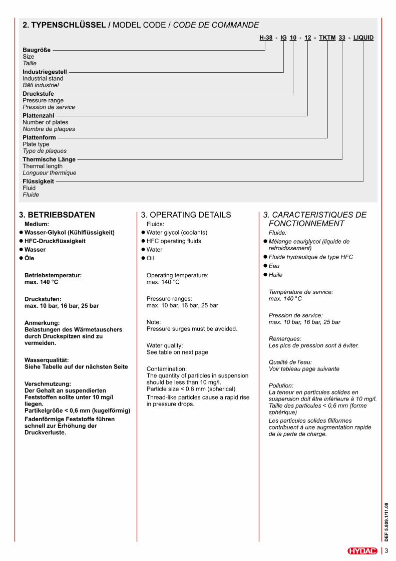
3. BETRIEBSDATENMedium:
l Wasser-Glykol (Kühlflüssigkeit)l HFC-Druckflüssigkeitl Wasserl Öle
Betriebstemperatur: max. 140 °C
Druckstufen: max. 10 bar, 16 bar, 25 bar
Anmerkung: Belastungen des Wärmetauschers durch Druckspitzen sind zu vermeiden.
Wasserqualität: Siehe Tabelle auf der nächsten Seite
Verschmutzung: Der Gehalt an suspendierten Feststoffen sollte unter 10 mg/l liegen. Partikelgröße < 0,6 mm (kugelförmig)Fadenförmige Feststoffe führen schnell zur Erhöhung der Druckverluste.
3. OPERATING DETAILSFluids:
l Water glycol (coolants)l HFC operating fluidsl Waterl Oil
Operating temperature: max. 140 °C
Pressure ranges: max. 10 bar, 16 bar, 25 bar
Note: Pressure surges must be avoided.
Water quality: See table on next page
Contamination: The quantity of particles in suspension should be less than 10 mg/l. Particle size < 0.6 mm (spherical)Thread-like particles cause a rapid rise in pressure drops.
3. CARACTERISTIQUES DE FONCTIONNEMENTFluide:
l Mélange eau/glycol (liquide de refroidissement)
l Fluide hydraulique de type HFCl Eaul Huile
Température de service: max. 140 °C
Pression de service: max. 10 bar, 16 bar, 25 bar
Remarques: Les pics de pression sont à éviter.
Qualité de l'eau: Voir tableau page suivante
Pollution: La teneur en particules solides en suspension doit être inférieure à 10 mg/l. Taille des particules < 0,6 mm (forme sphérique)Les particules solides filiformes contribuent à une augmentation rapide de la perte de charge.
H-38 - IG 10 - 12 - TKTM 33 - LIQUID
BaugrößeSize TailleIndustriegestell Industrial stand Bâti industrielDruckstufe Pressure range Pression de servicePlattenzahl Number of plates Nombre de plaquesPlattenform Plate type Type de plaquesThermische Länge Thermal length Longueur thermiqueFlüssigkeit Fluid Fluide
2. TYPENSCHLÜSSEL / MODEL CODE / CODE DE COMMANDE
4
DEF
5.8
09.1
/11.
09
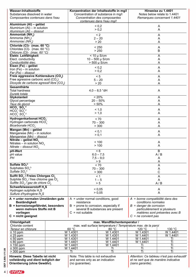
Wasser-InhaltsstoffeSubstances dissolved in water Composantes contenues dans l'eau
Konzentration der Inhaltsstoffe in mg/lConcentration of substance in mg/l Concentration des composantes
contenues dans l'eau mg/l
Hinweise zu 1.4401Notes below relate to 1.4401
Remarques concernant 1.4401
Aluminium (Al) – gelöst Aluminium (Al) – in solution Aluminium (Al) – dissout
< 0,2 > 0,2
A A
Ammoniak (NH3)Ammonia (NH3)Ammoniac (NH3)
< 2 2 – 20 > 20
A A A
Chloride (Cl)- (max. 60 °C)Chlorides (Cl)- (max. 60 °C) Chlorure (Cl)- (max. 60 °C)
< 250 > 250
A B
Elektr. Leitfähigkeit Elect. conductivity Conductibilité élec.
< 10 μ S/cm 10 – 500 μ S/cm
> 500 μ S/cm
A A A
Eisen (Fe) – gelöst Iron (Fe) – in solution Fer (Fe) – dissout
< 0,2 > 0,2
A A
Freie aggressive Kohlensäure (CO2)Free agressive carbonic acid (CO2)Dioxyde de carbone agressif libre (CO2)
< 5 5 – 20 > 20
A A A
GesamthärteTotal hardness Dureté totale
4,0 – 8,5 °dH A
Glykolanteil Glycol percentage Taux de glycol
< 20% 20 – 50%
> 50%
A A A
HCO3- SO4
-2
HCO3- SO4
-2
HCO3- SO4
-2
< 1,0 > 1,0
A A
Hydrogenkarbonat HCO3-
Hydrogen carbonate HCO3-
Bicarbonate HCO3-
< 70 70 – 300
> 300
A A A
Mangan (Mn) – gelöst Manganese (Mn) – in solution Manganèse (Mn) – dissout
< 0,1 > 0,1
A A
Nitrate – gelöst NO3Nitrates – in solution NO3Nitrate – dissout NO3
< 100 > 100
A A
pH-Wert pH value PH
< 6 6.0 – 7,5 7,5 – 9,0
> 9
B A / B
A A
Sulfate SO42-
Sulphates SO42-
Sulfate SO42-
< 70 70 – 300
> 300
A A C
Sulfit SO3 / Freies Chlorgas Cl2Sulphite SO3 / free chlorine gas Cl2Sulfite SO3 / gaz de chlore Cl2
< 1 1 – 5 > 5
A A
A / BSchwefelwasserstoff H2SHydrogen sulphide H2SSulfure d'hydrogène H2S
< 0,05 > 0,05
A A
Hinweis: Diese Tabelle ist nicht vollständig und dient lediglich der Orientierung (ohne Gewähr).
Note: This table is not exhaustive and serves only as an indication (no guarantee).
Attention: Ce tableau n'est pas exhaustif et ne sert que de manière indicative (sans garantie).
A = bonne compatibilité dans des conditions normales B = danger de corrosion particulièrement si plusieurs matières sont présentes avec B C = ne convient pas
A = under normal conditions, good resistance B = prone to corrosion, especially if several B substances are present C = not suitable
A = unter normalen Umständen gute Beständigkeit B = korrosionsgefährdet, besonders wenn mehrere Stoffe mit B vorliegen C = nicht geeignet
Chloridgehalt Chloride contentTeneur en chlorure
max. Wandflächentemperatur / max. wall surface temperature / Température max. de la paroi
60 °C 80 °C 120 °C 130 °C≤ 10 ppm W 1.4301 W 1.4301 W 1.4301 W 1.4401≤ 25 ppm W 1.4301 W 1.4301 W 1.4401 W 1.4401≤ 50 ppm W 1.4301 W 1.4401 W 1.4401 Ti≤ 80 ppm W 1.4401 W 1.4401 W 1.4401 Ti≤ 150 ppm W 1.4401 W 1.4401 Ti Ti≤ 300 ppm W 1.4401 Ti Ti Ti> 300 ppm Ti Ti Ti Ti
5
DEF
5.8
09.1
/11.
09
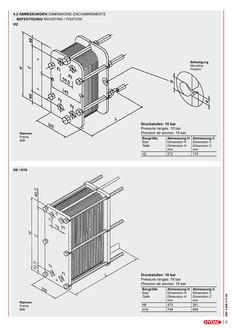
4.2 ABMESSUNGEN/ DIMENSIONS/ ENCOMBREMENTS BEFESTIGUNG/ MOUNTING / FIXATION
Druckstufen: 10 bar Pressure ranges: 10 bar Pression de service: 10 barBaugröße SizeTaille
Abmessung H Dimension HDimension Hmm
Abmessung C Dimension CDimension Cmm
H2 272 175
Druckstufen: 16 bar Pressure ranges: 16 bar Pression de service: 16 barBaugröße SizeTaille
Abmessung H Dimension HDimension Hmm
Abmessung C Dimension CDimension Cmm
H8 473 381H16 748 656
BefestigungMountingFixation
RahmenFrame Bâti
RahmenFrame Bâti
H2
H8 / H16
6
DEF
5.8
09.1
/11.
09
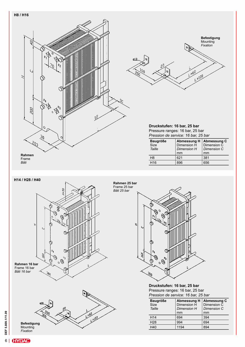
Druckstufen: 16 bar, 25 bar Pressure ranges: 16 bar, 25 bar Pression de service: 16 bar, 25 barBaugröße SizeTaille
Abmessung H Dimension HDimension Hmm
Abmessung C Dimension CDimension Cmm
H8 621 381H16 896 656
BefestigungMountingFixation
RahmenFrame Bâti
H8 / H16
Druckstufen: 16 bar, 25 bar Pressure ranges: 16 bar, 25 bar Pression de service: 16 bar, 25 barBaugröße SizeTaille
Abmessung H Dimension HDimension Hmm
Abmessung C Dimension CDimension Cmm
H14 694 394H28 994 694H40 1194 894
BefestigungMountingFixation
Rahmen 25 barFrame 25 bar Bâti 25 bar
Rahmen 16 barFrame 16 bar Bâti 16 bar
H14 / H28 / H40
7
DEF
5.8
09.1
/11.
09
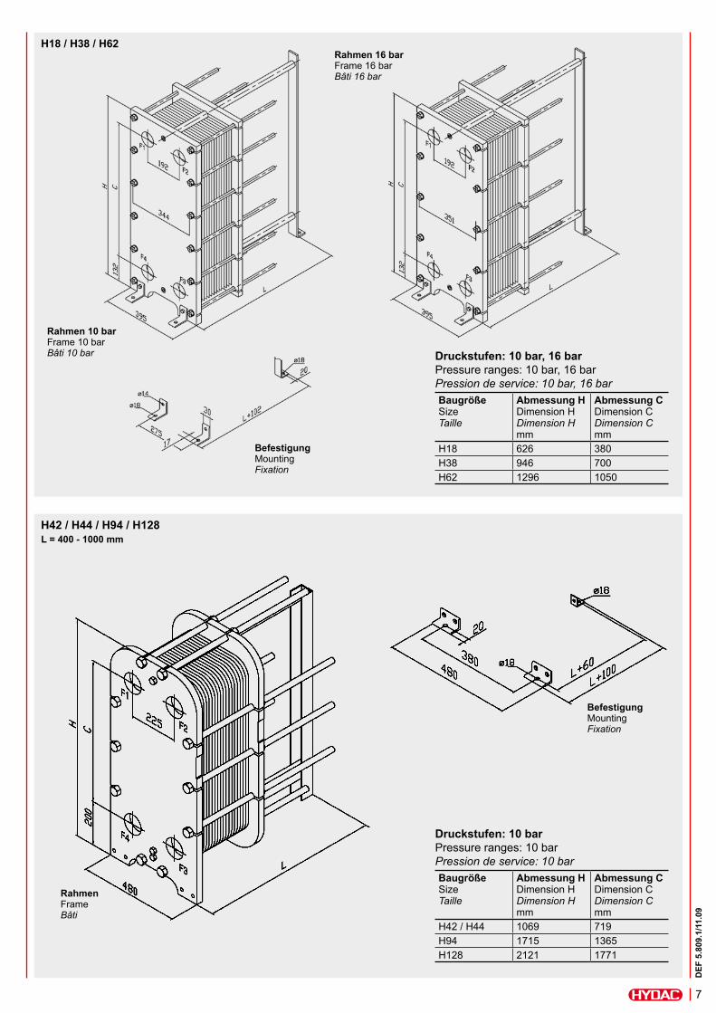
Druckstufen: 10 bar, 16 bar Pressure ranges: 10 bar, 16 bar Pression de service: 10 bar, 16 barBaugröße SizeTaille
Abmessung H Dimension HDimension Hmm
Abmessung C Dimension CDimension Cmm
H18 626 380H38 946 700H62 1296 1050
BefestigungMountingFixation
Rahmen 10 barFrame 10 bar Bâti 10 bar
Rahmen 16 barFrame 16 bar Bâti 16 bar
H18 / H38 / H62
Druckstufen: 10 bar Pressure ranges: 10 bar Pression de service: 10 barBaugröße SizeTaille
Abmessung H Dimension HDimension Hmm
Abmessung C Dimension CDimension Cmm
H42 / H44 1069 719H94 1715 1365H128 2121 1771
BefestigungMountingFixation
RahmenFrame Bâti
L = 400 - 1000 mmH42 / H44 / H94 / H128
8
DEF
5.8
09.1
/11.
09
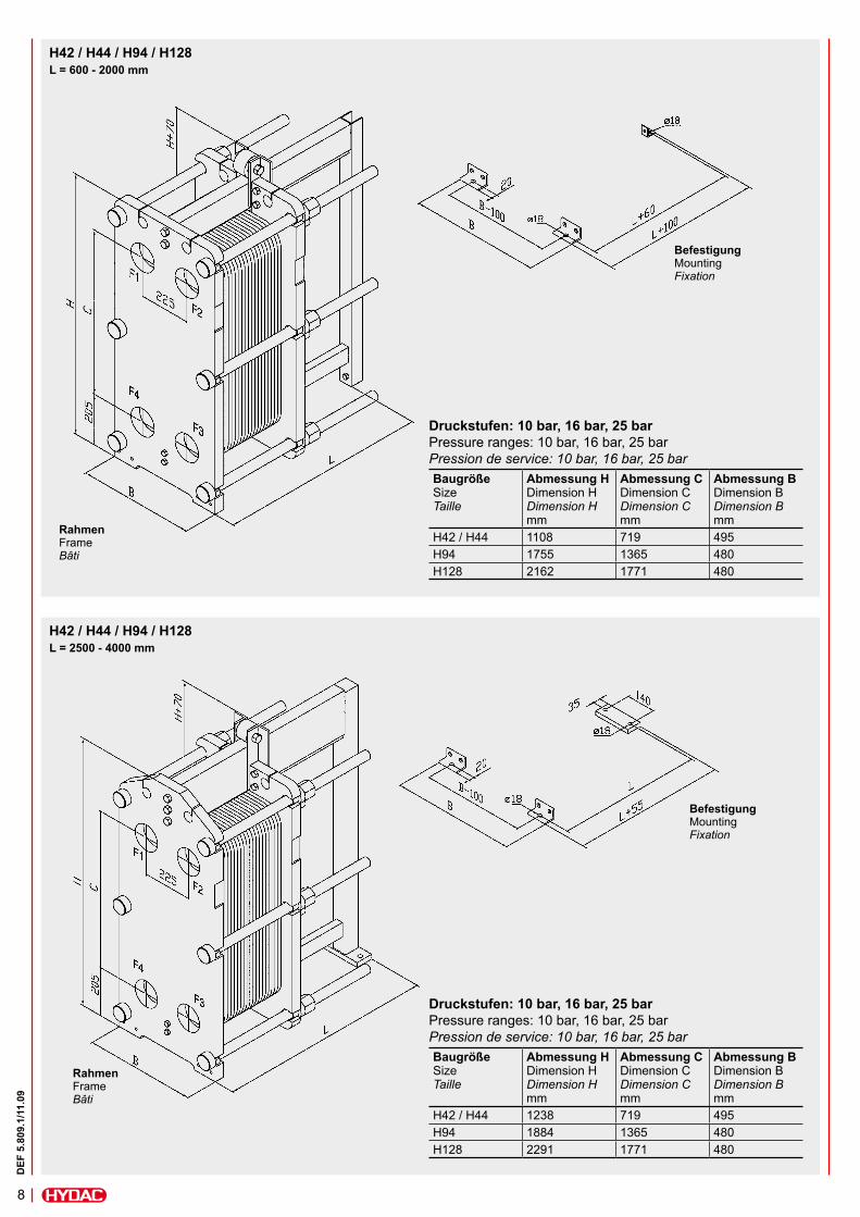
Druckstufen: 10 bar, 16 bar, 25 bar Pressure ranges: 10 bar, 16 bar, 25 bar Pression de service: 10 bar, 16 bar, 25 barBaugröße SizeTaille
Abmessung H Dimension HDimension Hmm
Abmessung C Dimension CDimension Cmm
Abmessung B Dimension BDimension Bmm
H42 / H44 1108 719 495H94 1755 1365 480H128 2162 1771 480
H42 / H44 / H94 / H128
BefestigungMountingFixation
RahmenFrame Bâti
H42 / H44 / H94 / H128
Druckstufen: 10 bar, 16 bar, 25 bar Pressure ranges: 10 bar, 16 bar, 25 bar Pression de service: 10 bar, 16 bar, 25 barBaugröße SizeTaille
Abmessung H Dimension HDimension Hmm
Abmessung C Dimension CDimension Cmm
Abmessung B Dimension BDimension Bmm
H42 / H44 1238 719 495H94 1884 1365 480H128 2291 1771 480
BefestigungMountingFixation
RahmenFrame Bâti
L = 2500 - 4000 mm
L = 600 - 2000 mm
9
DEF
5.8
09.1
/11.
09
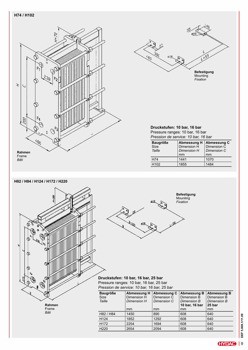
Druckstufen: 10 bar, 16 bar, 25 bar Pressure ranges: 10 bar, 16 bar, 25 bar Pression de service: 10 bar, 16 bar, 25 barBaugröße SizeTaille
Abmessung H Dimension HDimension H mm
Abmessung C Dimension CDimension C mm
Abmessung B Dimension BDimension B 10 bar, 16 bar mm
Abmessung B Dimension BDimension B 25 bar mm
H82 / H84 1450 890 608 640H124 1852 1292 608 640H172 2254 1694 608 640H220 2654 2094 608 640
BefestigungMountingFixation
RahmenFrame Bâti
H82 / H84 / H124 / H172 / H220
Druckstufen: 10 bar, 16 bar Pressure ranges: 10 bar, 16 bar Pression de service: 10 bar, 16 barBaugröße SizeTaille
Abmessung H Dimension HDimension Hmm
Abmessung C Dimension CDimension Cmm
H74 1441 1070H102 1855 1484
H74 / H102
BefestigungMountingFixation
RahmenFrame Bâti
10
DEF
5.8
09.1
/11.
09
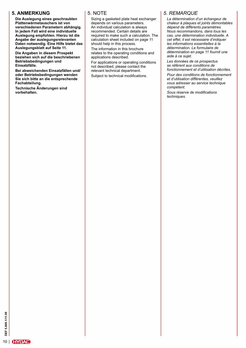
5. ANMERKUNGDie Auslegung eines geschraubten Plattenwärmetauschers ist von verschiedenen Parametern abhängig. In jedem Fall wird eine individuelle Auslegung empfohlen. Hierzu ist die Angabe der auslegungsrelevanten Daten notwendig. Eine Hilfe bietet das Auslegungsblatt auf Seite 11.Die Angaben in diesem Prospekt beziehen sich auf die beschriebenen Betriebsbedingungen und Einsatzfälle.Bei abweichenden Einsatzfällen und/oder Betriebsbedingungen wenden Sie sich bitte an die entsprechende Fachabteilung. Technische Änderungen sind vorbehalten.
5. NOTESizing a gasketed plate heat exchanger depends on various parameters. An individual calculation is always recommended. Certain details are required to make such a calculation. The calculation sheet included on page 11 should help in this process.The information in this brochure relates to the operating conditions and applications described. For applications or operating conditions not described, please contact the relevant technical department.Subject to technical modifications.
5. REMARQUELa détermination d’un échangeur de chaleur à plaques et joints démontables dépend de différents paramètres. Nous recommandons, dans tous les cas, une détermination individuelle. A cet effet, il est nécessaire d’indiquer les informations essentielles à la détermination. Le formulaire de détermination en page 11 fournit une aide à ce sujet.Les données de ce prospectus se réfèrent aux conditions de fonctionnement et d’utilisation décrites.Pour des conditions de fonctionnement et d’utilisation différentes, veuillez vous adresser au service technique compétent. Sous réserve de modifications techniques.
11
DEF
5.8
09.1
/11.
09
Cooling GmbHIndustriegebiet D-66280 Sulzbach/Saar Tel.: 0 68 97 / 509-01 Telefax: 0 68 97 / 509-454 Internet: www.hydac.com E-Mail: [email protected]
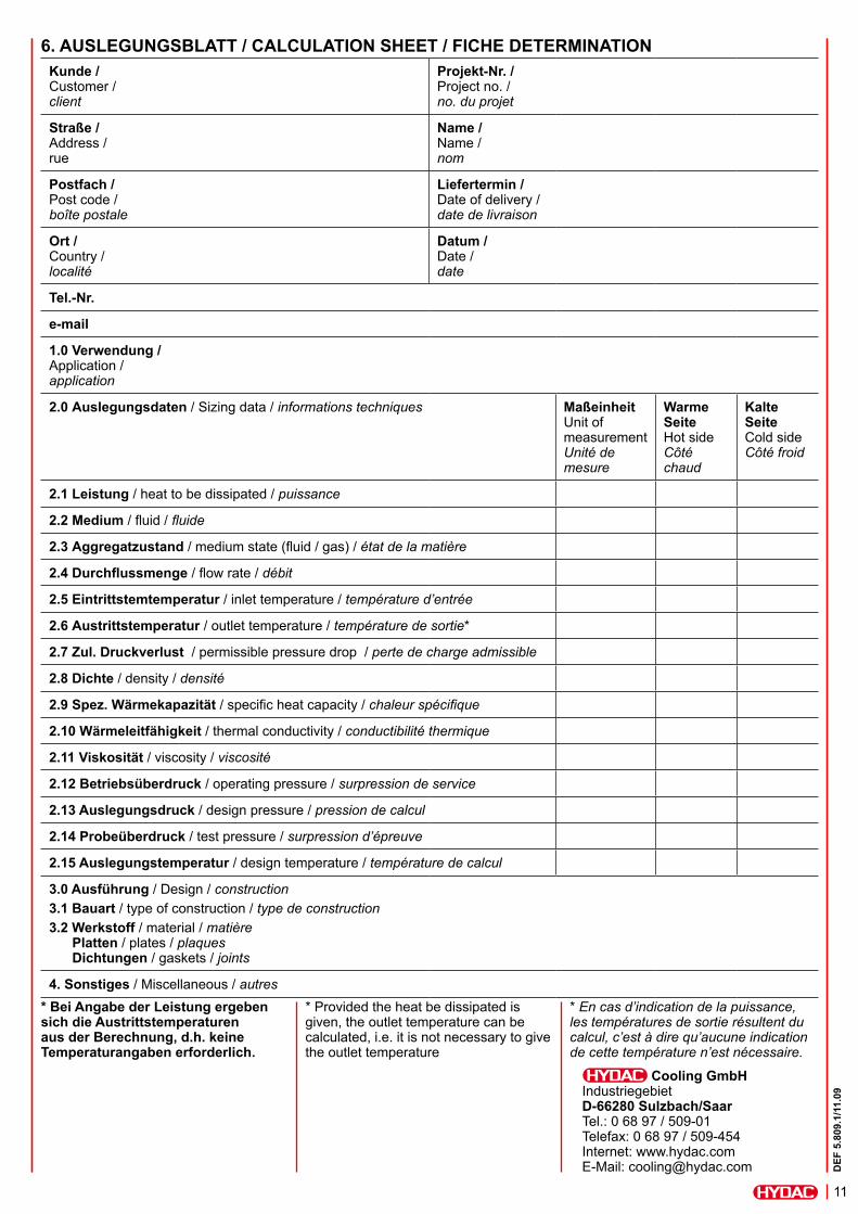
* Bei Angabe der Leistung ergeben sich die Austrittstemperaturen aus der Berechnung, d.h. keine Temperaturangaben erforderlich.
Kunde / Customer / client
Projekt-Nr. / Project no. / no. du projet
Straße / Address / rue
Name / Name / nom
Postfach / Post code / boîte postale
Liefertermin / Date of delivery / date de livraison
Ort / Country / localité
Datum / Date / date
Tel.-Nr.
1.0 Verwendung / Application / application
2.0 Auslegungsdaten / Sizing data / informations techniques MaßeinheitUnit of measurement Unité de mesure
Warme SeiteHot side Côté chaud
Kalte SeiteCold side Côté froid
2.1 Leistung / heat to be dissipated / puissance
2.2 Medium / fluid / fluide
2.3 Aggregatzustand / medium state (fluid / gas) / état de la matière
2.4 Durchflussmenge / flow rate / débit
2.5 Eintrittstemtemperatur / inlet temperature / température d’entrée
2.6 Austrittstemperatur / outlet temperature / température de sortie*
2.7 Zul. Druckverlust / permissible pressure drop / perte de charge admissible
2.8 Dichte / density / densité
2.9 Spez. Wärmekapazität / specific heat capacity / chaleur spécifique
2.10 Wärmeleitfähigkeit / thermal conductivity / conductibilité thermique
2.11 Viskosität / viscosity / viscosité
2.12 Betriebsüberdruck / operating pressure / surpression de service
2.13 Auslegungsdruck / design pressure / pression de calcul
2.14 Probeüberdruck / test pressure / surpression d’épreuve
2.15 Auslegungstemperatur / design temperature / température de calcul
3.0 Ausführung / Design / construction3.1 Bauart / type of construction / type de construction3.2 Werkstoff / material / matière Platten / plates / plaques Dichtungen / gaskets / joints
4. Sonstiges / Miscellaneous / autres* Provided the heat be dissipated is given, the outlet temperature can be calculated, i.e. it is not necessary to give the outlet temperature
* En cas d’indication de la puissance, les températures de sortie résultent du calcul, c’est à dire qu’aucune indication de cette température n’est nécessaire.
6. AUSLEGUNGSBLATT / CALCULATION SHEET / FICHE DETERMINATION
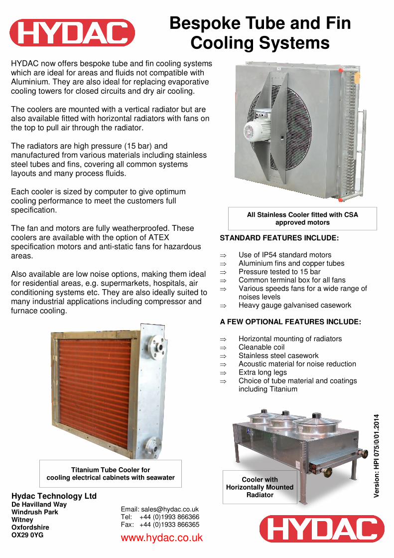
Bespoke Tube and Fin Cooling Systems
HYDAC now offers bespoke tube and fin cooling systems which are ideal for areas and fluids not compatible with Aluminium. They are also ideal for replacing evaporative cooling towers for closed circuits and dry air cooling. The coolers are mounted with a vertical radiator but are also available fitted with horizontal radiators with fans on the top to pull air through the radiator. The radiators are high pressure (15 bar) and manufactured from various materials including stainless steel tubes and fins, covering all common systems layouts and many process fluids. Each cooler is sized by computer to give optimum cooling performance to meet the customers full specification. The fan and motors are fully weatherproofed. These coolers are available with the option of ATEX specification motors and anti-static fans for hazardous areas. Also available are low noise options, making them ideal for residential areas, e.g. supermarkets, hospitals, air conditioning systems etc. They are also ideally suited to many industrial applications including compressor and furnace cooling.
STANDARD FEATURES INCLUDE: ⇒ Use of IP54 standard motors ⇒ Aluminium fins and copper tubes ⇒ Pressure tested to 15 bar ⇒ Common terminal box for all fans ⇒ Various speeds fans for a wide range of
noises levels ⇒ Heavy gauge galvanised casework A FEW OPTIONAL FEATURES INCLUDE: ⇒ Horizontal mounting of radiators ⇒ Cleanable coil ⇒ Stainless steel casework ⇒ Acoustic material for noise reduction ⇒ Extra long legs ⇒ Choice of tube material and coatings including Titanium
Hydac Technology Ltd De Havilland Way Windrush Park Witney Oxfordshire OX29 0YG
Email: [email protected] Tel: +44 (0)1993 866366 Fax: +44 (0)1933 866365
www.hydac.co.uk
All Stainless Cooler fitted with CSA approved motors
Titanium Tube Cooler for cooling electrical cabinets with seawater Cooler with
Horizontally Mounted Radiator V
ers
ion
: H
PI 075/0
/01.2
014
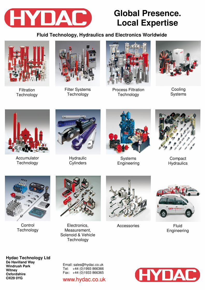
Global Presence. Local Expertise
Fluid Technology, Hydraulics and Electronics Worldwide
Filtration Technology
Filter Systems Technology
Process Filtration Technology
Cooling Systems
Accumulator Technology
Hydraulic Cylinders
Systems Engineering
Compact Hydraulics
Control Technology
Electronics, Measurement,
Solenoid & Vehicle Technology
Accessories Fluid Engineering
Hydac Technology Ltd De Havilland Way Windrush Park Witney Oxfordshire OX29 0YG
Email: [email protected] Tel: +44 (0)1993 866366 Fax: +44 (0)1933 866365
www.hydac.co.uk