hydraulic cylinders - hps international
TRANSCRIPT
08/21
International
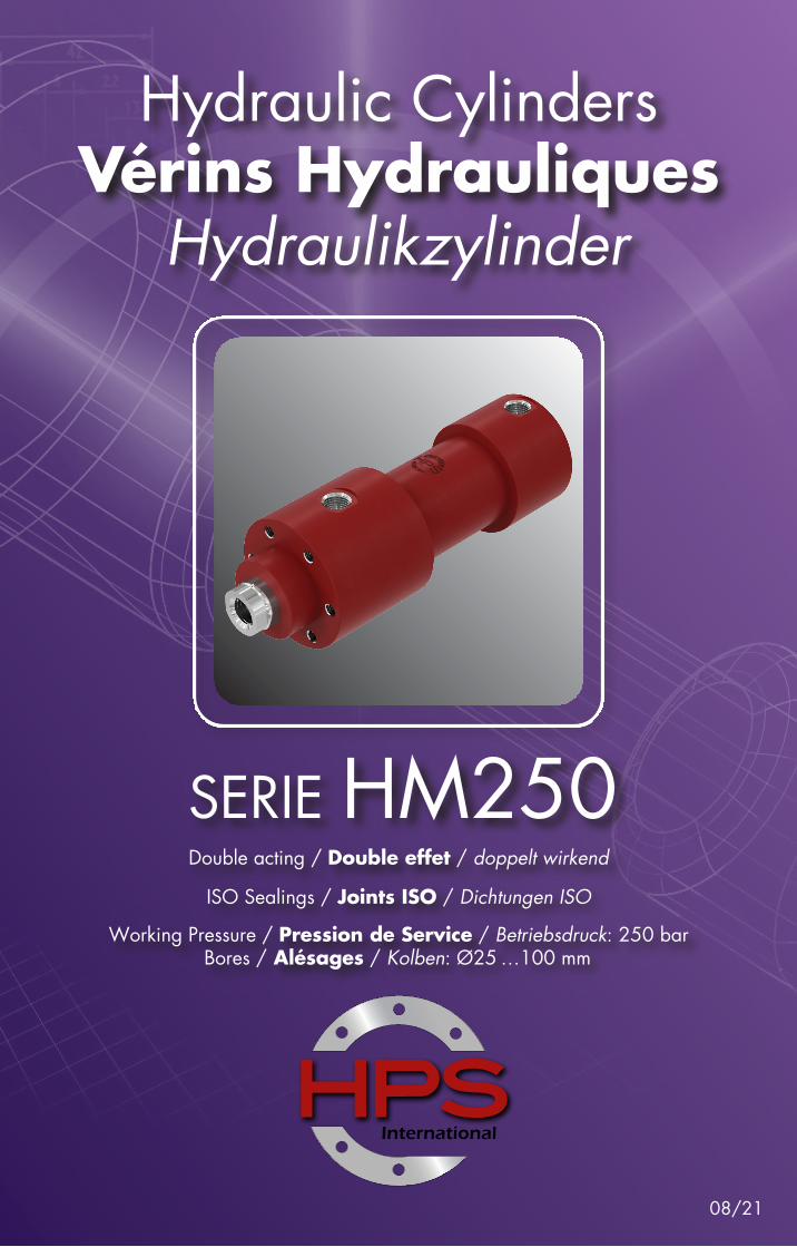
Hydraulic CylindersVérins Hydrauliques
Hydraulikzylinder
SERIE HM250Working Pressure / Pression de Service / Betriebsdruck: 250 bar
Bores / Alésages / Kolben: Ø25 …100 mm
Double acting / Double effet / doppelt wirkend
ISO Sealings / Joints ISO / Dichtungen ISO
2
International
SERIE HM250
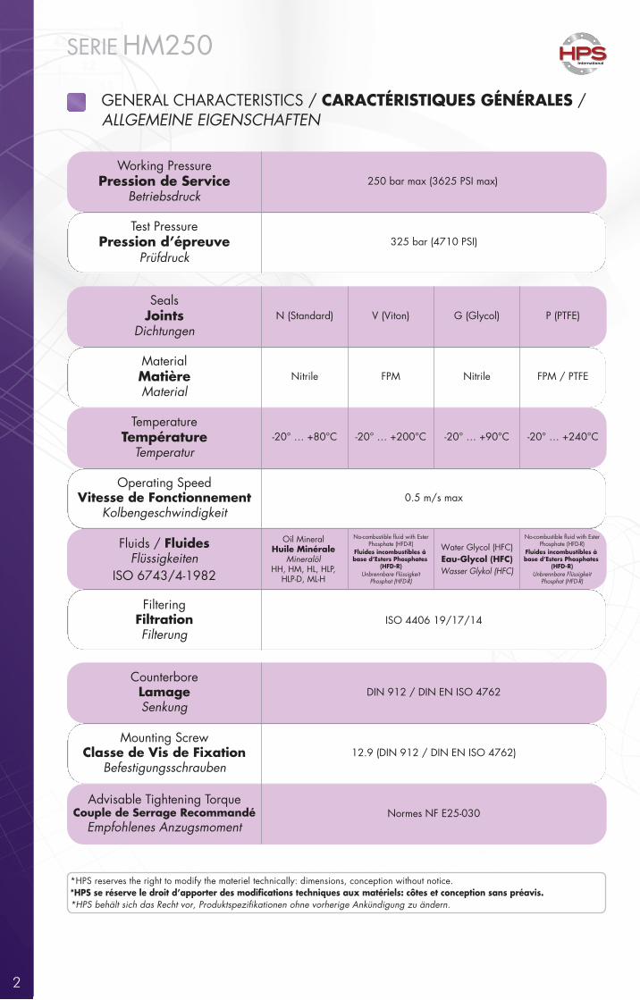
GENERAL CHARACTERISTICS / CARACTÉRISTIQUES GÉNÉRALES / ALLGEMEINE EIGENSCHAFTEN
Working PressurePression de Service
Betriebsdruck
Test PressurePression d’épreuve
Prüfdruck
SealsJoints
Dichtungen
MaterialMatièreMaterial
TemperatureTempérature
Temperatur
Operating SpeedVitesse de Fonctionnement
Kolbengeschwindigkeit
Fluids / FluidesFlüssigkeiten
ISO 6743/4-1982
FilteringFiltrationFilterung
Oil MineralHuile Minérale
MineralölHH, HM, HL, HLP,
HLP-D, ML-H
CounterboreLamageSenkung
Mounting ScrewClasse de Vis de Fixation
Befestigungsschrauben
Advisable Tightening TorqueCouple de Serrage Recommandé
Empfohlenes Anzugsmoment
ISO 4406 19/17/14
DIN 912 / DIN EN ISO 4762
12.9 (DIN 912 / DIN EN ISO 4762)
Normes NF E25-030
N (Standard) V (Viton) G (Glycol)
Nitrile FPM Nitrile
-20° … +80°C -20° … +200°C -20° … +90°C
0.5 m/s max
P (PTFE)
FPM / PTFE
-20° … +240°C
250 bar max (3625 PSI max)
325 bar (4710 PSI)
Phosphate (HFD-R)No-combustible �uid with EsterNo-combustible �uid with Ester
Fluides incombustibles à base d’Esters Phosphates
(HFD-R)Unbrennbare Flüssigkeit
Phosphat (HFD-R)
Phosphate (HFD-R)Fluides incombustibles à base d’Esters Phosphates
(HFD-R)Unbrennbare Flüssigkeit
Phosphat (HFD-R)
Water Glycol (HFC)Eau-Glycol (HFC)Wasser Glykol (HFC)
*HPS reserves the right to modify the materiel technically: dimensions, conception without notice.*HPS se réserve le droit d’apporter des modi�cations techniques aux matériels: côtes et conception sans préavis.*HPS behält sich das Recht vor, Produktspezifikationen ohne vorherige Ankündigung zu ändern.
3
International
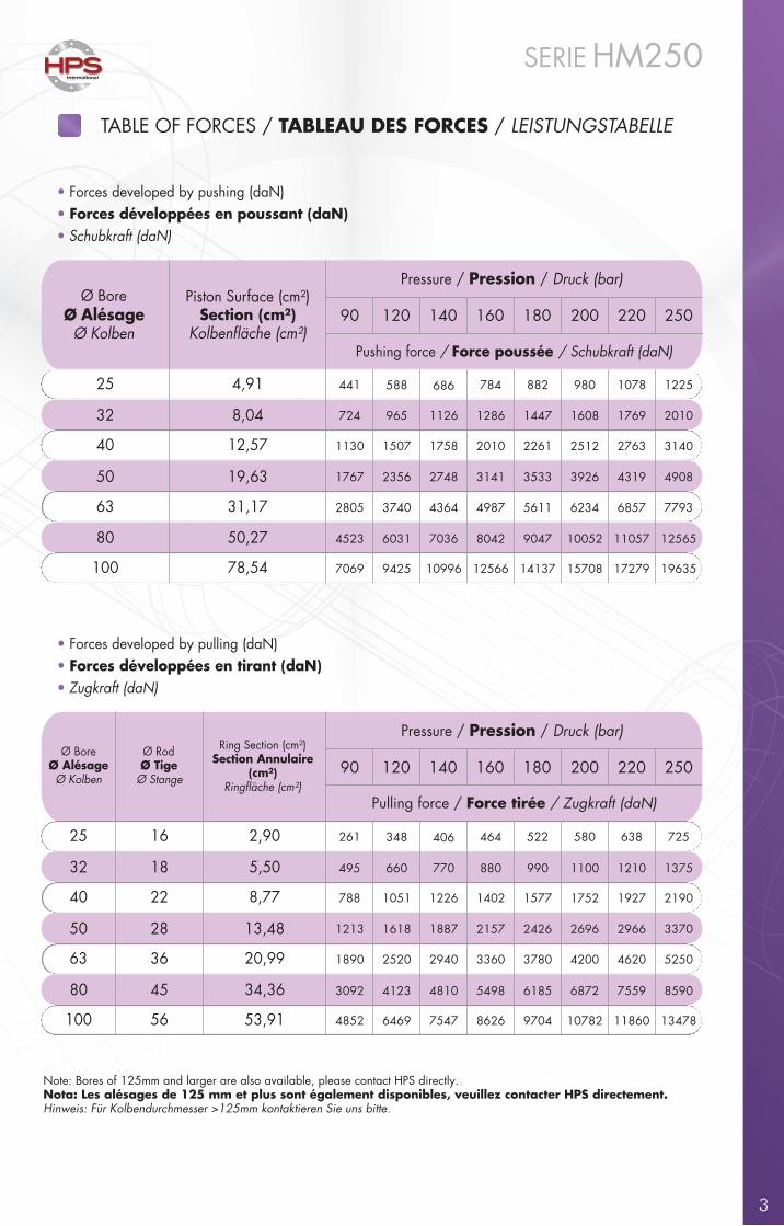
TABLE OF FORCES / TABLEAU DES FORCES / LEISTUNGSTABELLE
SERIE HM250
• Forces developed by pushing (daN)• Forces développées en poussant (daN)• Schubkraft (daN)
• Forces developed by pulling (daN)• Forces développées en tirant (daN)• Zugkraft (daN)
Ø BoreØ Alésage
Ø Kolben
Piston Surface (cm²)Section (cm²)
Pressure / Pression / Druck (bar)
90 120 140 160
25
32
40
50
63
80
4,91
8,04
12,57
19,63
31,17
50,27
441
724
1130
1767
2805
4523
588
965
1507
2356
3740
6031
686
1126
1758
2748
4364
7036
784
1286
Pushing force / Force poussée / Schubkraft (daN)
200
980
1608
2512
3926
6234
10052
180
1447
882
8042
4987
3141
2010
3533
2261
5611
9047
100 78,54 7069 9425 10996 1570812566 14137
250
1225
2010
3140
4908
7793
12565
220
1769
1078
4319
2763
6857
11057
1963517279
Ø BoreØ AlésageØ Kolben
Ring Section (cm²)Section Annulaire
(cm²)
Pressure / Pression / Druck (bar)
25
32
40
50
63
80
2,90
5,50
8,77
13,48
20,99
34,36
Pulling force / Force tirée / Zugkraft (daN)
100 53,91
Ø RodØ Tige
Ø Stange
16
18
22
28
36
45
56
90 120 140 160
261
495
788
1213
1890
3092
348
660
1051
1618
2520
4123
406
770
1226
1887
2940
4810
464
880
200
580
1100
1752
2696
4200
6872
180
990
522
5498
3360
2157
1402
2426
1577
3780
6185
4852 6469 7547 107828626 9704
250
725
1375
2190
3370
5250
8590
220
1210
638
2966
1927
4620
7559
1347811860
Note: Bores of 125mm and larger are also available, please contact HPS directly.Nota: Les alésages de 125 mm et plus sont également disponibles, veuillez contacter HPS directement.Hinweis: Für Kolbendurchmesser >125mm kontaktieren Sie uns bitte.
4
International
SERIE HM250
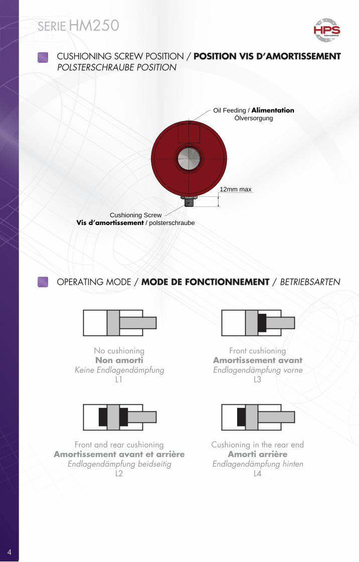
OPERATING MODE / MODE DE FONCTIONNEMENT / BETRIEBSARTEN
No cushioningNon amorti
Keine EndlagendämpfungL1
Front and rear cushioningAmortissement avant et arrière
Endlagendämpfung beidseitigL2
Cushioning in the rear endAmorti arrière
Endlagendämpfung hintenL4
Front cushioningAmortissement avantEndlagendämpfung vorne
L3
CUSHIONING SCREW POSITION / POSITION VIS D’AMORTISSEMENTPOLSTERSCHRAUBE POSITION
Cushioning ScrewVis d’amortissement / polsterschraube
Oil Feeding / AlimentationÖlversorgung
12mm max
ØM
LM S
ØM
M
K
r
Ø N
C
Ø N
B
ND NE S
Ø M
M
nx45°K
LM
Ø M
M
SØ
NFK
5
International
SERIE HM250
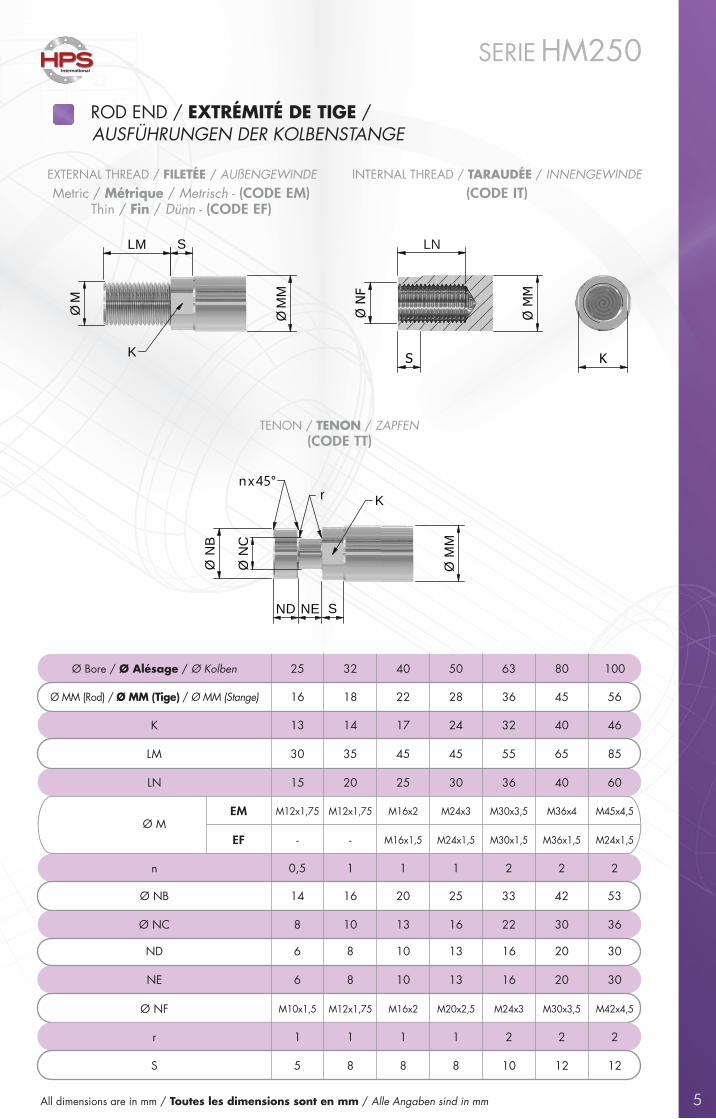
Ø Bore / Ø Alésage / Ø Kolben 25 32 40 50 63 80 100
K
LM
Ø NB
ND
Ø NC
NE
Ø NF
16 18 22 28 36 45 56
13 14 17 24 32 40 46
30 35 45 45 55 65 85
14 16 20 25 33 42 53
8 10 13 302216 36
6 8 10 13 16 20 30
6 8 10 13 16 20 30
0,5 1 1 1 2 2 2
Ø MM (Rod) / Ø MM (Tige) / Ø MM (Stange)
n
- M24x1,5M36x1,5M30x1,5M24x1,5M16x1,5-
M12x1,75Ø M
EF
EM M45x4,5M36x4M30x3,5M24x3M16x2M12x1,75
M10x1,5 M42x4,5M30x3,5M24x3M20x2,5M16x2M12x1,75
LN
S
20 25 30 36 40 60
5 8 8 8 10 1212
15
r 1 1 1 2 2 21
ROD END / EXTRÉMITÉ DE TIGE / AUSFÜHRUNGEN DER KOLBENSTANGE
EXTERNAL THREAD / FILETÉE / AUßENGEWINDE INTERNAL THREAD / TARAUDÉE / INNENGEWINDE(CODE IT)Metric / Métrique / Metrisch - (CODE EM)
Thin / Fin / Dünn - (CODE EF)
TENON / TENON / ZAPFEN(CODE TT)
All dimensions are in mm / Toutes les dimensions sont en mm / Alle Angaben sind in mm
LN
Y L + Stroke / Course / Hub
J
F
Ø M
M
MØ B
P
Ø B
N N ( F1 )
N( F0 )
L + Stroke / Course / Hub Y
F PØ
MM
Ø C
I Q
Ø D
E equidistants
60°
N N ( F1 )
N(F0 )
Ø A
Ø B
L + Stroke / Course / Hub Y
F P
Ø M
M
Ø C
I Q
Ø D
E equidistants
60°
N N ( F1 )
N(F0 )
Ø A
Ø B
6
International
SERIE HM250
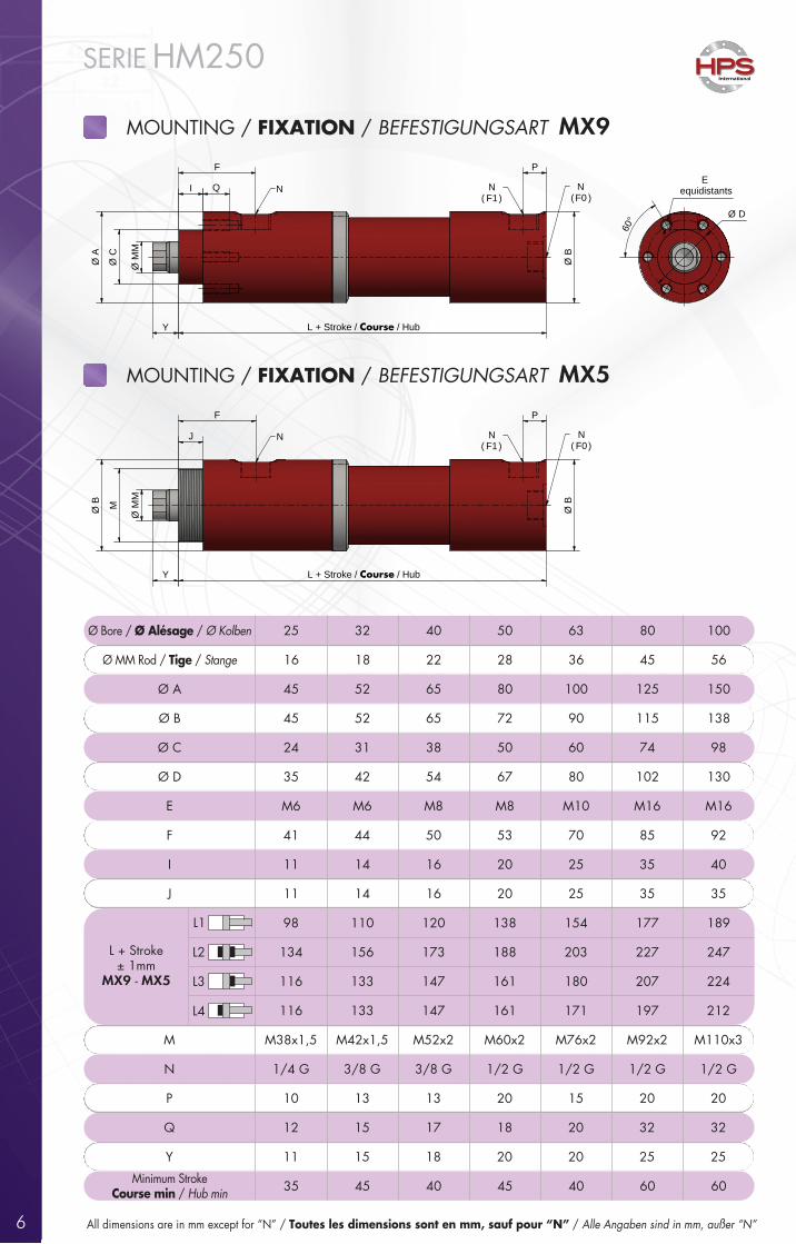
MOUNTING / FIXATION / BEFESTIGUNGSART MX9
MOUNTING / FIXATION / BEFESTIGUNGSART MX5
All dimensions are in mm except for “N” / Toutes les dimensions sont en mm, sauf pour “N” / Alle Angaben sind in mm, außer “N”
Ø Bore / Ø Alésage / Ø Kolben 25 32 40 50 63 80 100
Ø MM Rod / Tige / Stange 16 18 22 28 36 45 56
Ø A 45 52 65 80 100 125 150
Ø B 45 52 65 72 90 115 138
Ø C 24 31 38 50 60 74 98
Ø D 35 42 54 67 80 102 130
E M6 M6 M8 M8 M10 M16 M16
F 41 44 50 53 70 85 92
I 11 14 16 20 25 35 40
J 11 14 16 20 25 35 35
98 110 120 138 154 177 189
134 156 173 188 203 227 247
116 133 147 161 180 207 224
116 133 147 161 171 197 212
M M38x1,5 M42x1,5 M52x2 M60x2 M76x2 M92x2 M110x3
N 1/4 G 3/8 G 3/8 G 1/2 G 1/2 G 1/2 G 1/2 G
P 10 13 13 20 15 20 20
Q 12 15 17 18 20 32 32
Y 11 15 18 20 20 25 25
Minimum StrokeCourse min / Hub min 35 45 40 45 40 60 60
L + Stroke± 1mm
MX9 - MX5
L1
L2
L3
L4
7
International
SERIE HM250
Y
J
F
P
ØM
M
Ø C
N
Ø B
Ø B
N ( F1)
N( F0 )
L + Stroke / Course / Hub
Ø D
Ø Eequidistants
60°
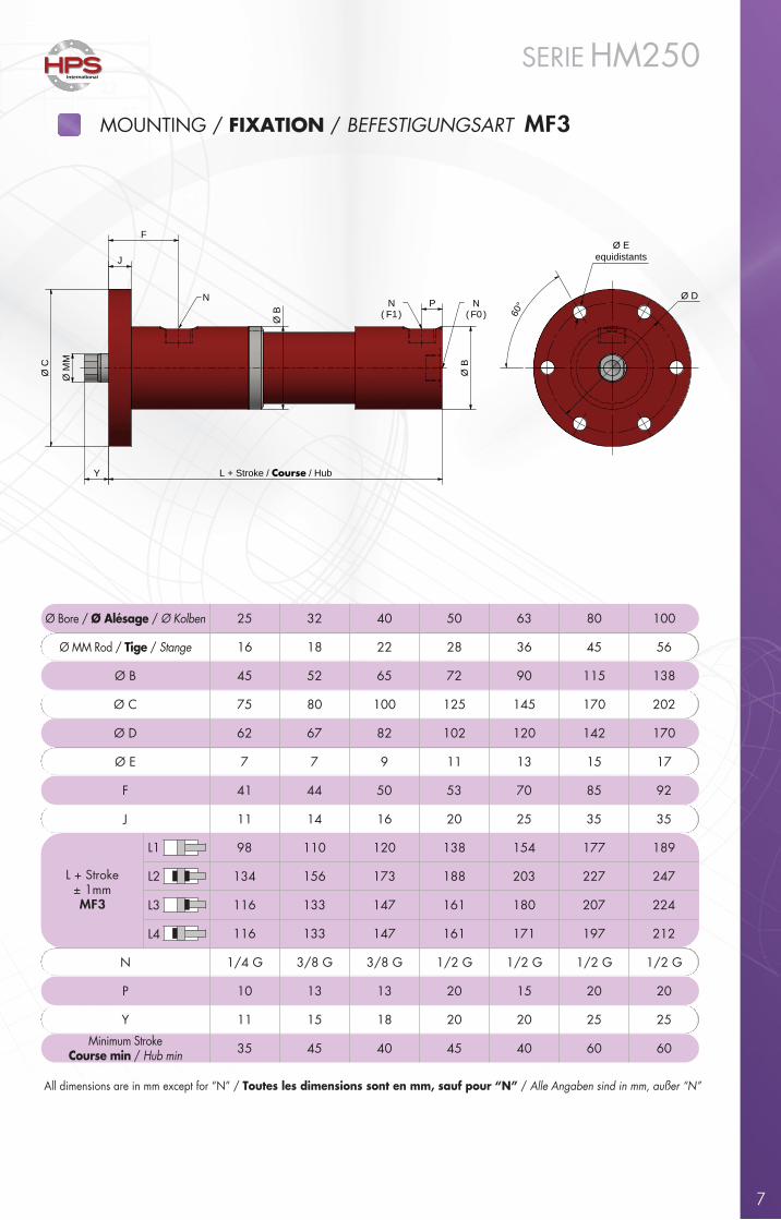
MOUNTING / FIXATION / BEFESTIGUNGSART MF3
All dimensions are in mm except for “N” / Toutes les dimensions sont en mm, sauf pour “N” / Alle Angaben sind in mm, außer “N”
Ø Bore / Ø Alésage / Ø Kolben 25 32 40 50 63 80 100
Ø MM Rod / Tige / Stange 16 18 22 28 36 45 56
Ø B 45 52 65 72 90 115 138
Ø C 75 80 100 125 145 170 202
Ø D
7 7 9 11 13 15 17Ø E
62 67 82 102 120 142 170
F 41 44 50 53 70 85 92
J 11 14 16 20 25 35 35
98 110 120 138 154 177 189
134 156 173 188 203 227 247
116 133 147 161 180 207 224
116 133 147 161 171 197 212
L + Stroke± 1mmMF3
N 1/4 G 3/8 G 3/8 G 1/2 G 1/2 G 1/2 G 1/2 G
P 10 13 13 20 15 20 20
Y 11 15 18 20 20 25 25
Minimum StrokeCourse min / Hub min 35 45 40 45 40 60 60
L1
L2
L3
L4
8
International
SERIE HM250
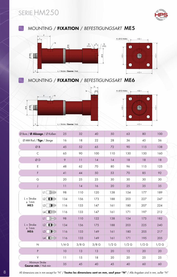
All dimensions are in mm except for “N” / Toutes les dimensions sont en mm, sauf pour “N” / Alle Angaben sind in mm, außer “N”
MOUNTING / FIXATION / BEFESTIGUNGSART ME5
Ø Bore / Ø Alésage / Ø Kolben 25 32 40 50 63 80 100
Ø MM Rod / Tige / Stange 16 18 22 28 36 45 56
Ø B 45 52 65 72 90 115 138
C 65 90 100 110 130 150 160
Ø D 9 11 14 14 18 18 18
E 48 62 70 80 96 115 125
F 41 44 50 53 70 85 92
G 20 25 25 30 30 30 30
J 11 14 16 20 25 35 35
98 110 120 138 154 177 189
134 156 173 188 203 227 247
116 133 147 161 180 207 224
116 133 147 161 171 197 212
98 110 122 138 154 175 182
134 156 175 188 203 225 240
L + Stroke± 1mmME5
L + Stroke± 1mmME6 116 133 149 161 180 205 217
116 133 149 161 171 195 205
N 1/4 G 3/8 G 3/8 G 1/2 G 1/2 G 1/2 G 1/2 G
P 10 13 13 20 15 20 20
Y 11 15 18 20 20 25 25
Minimum StrokeCourse min / Hub min 35 45 40 45 40 60 60
L1
L2
L3
L4
L1
L2
L3
L4
MOUNTING / FIXATION / BEFESTIGUNGSART ME6
Y L + Stroke / Course / Hub
J
F
P
Ø M
M
= C =
= C
=
= E
=
= E =
N
Ø B
Ø B
N ( F1 )
N( F0 )
4 x Ø D Holes
Y L + Stroke / Course / Hub
J
F
P
Ø M
M
= C =
= C
=
= E
=
= E =
N
Ø B
Ø B
N ( F1 )
N( F0 )
4 x Ø D Holes
Ø M
M
L + Stroke / Course / HubY
F
G/2
G
= C =
= C
=
= E =
= E
=
4 x Ø D Holes
Ø B
N
N
Ø M
M
L + Stroke / Course / HubY
F
G/2
G
= C =
= C
=
= E =
= E
=
4 x Ø D Holes
Ø B
N
N
9
International
SERIE HM250
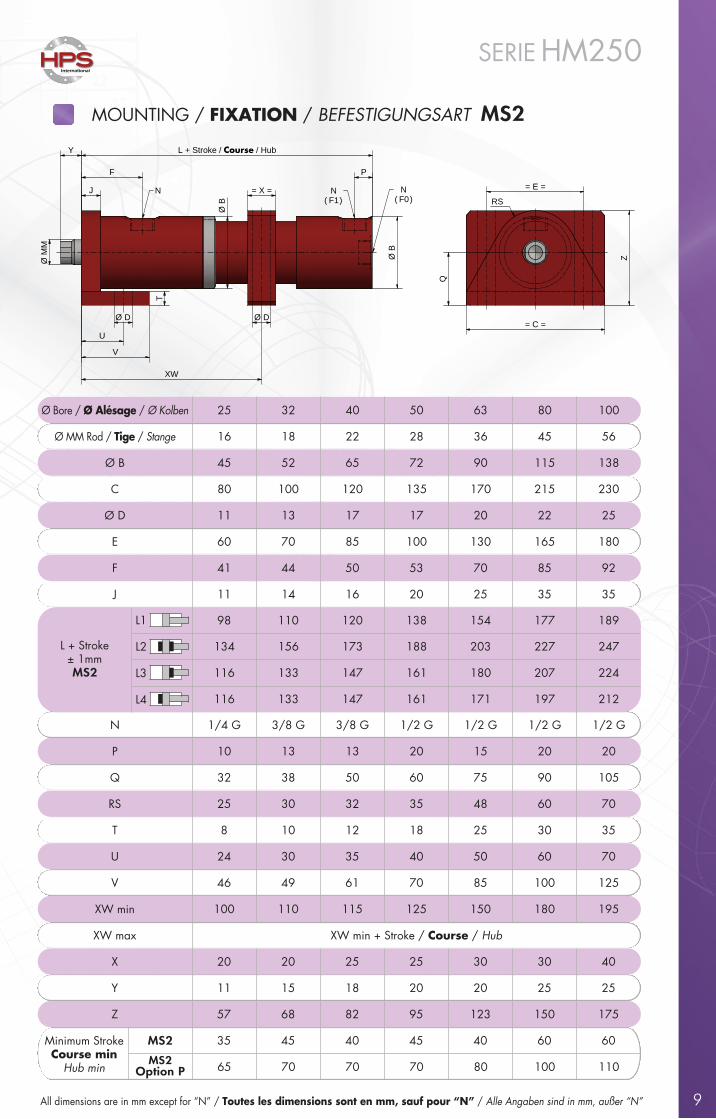
MOUNTING / FIXATION / BEFESTIGUNGSART MS2
All dimensions are in mm except for “N” / Toutes les dimensions sont en mm, sauf pour “N” / Alle Angaben sind in mm, außer “N”
Ø Bore / Ø Alésage / Ø Kolben 25 32 40 50 63 80 100
Ø MM Rod / Tige / Stange 16 18 22 28 36 45 56
Ø B 45 52 65 72 90 115 138
C 80 100 120 135 170 215 230
Ø D 11 13 17 17 20 22 25
E 60 70 85 100 130 165 180
F 41 44 50 53 70 85 92
J 11 14 16 20 25 35 35
98 110 120 138 154 177 189
L + Stroke± 1mmMS2
134 156 173 188 203 227 247
116 133 147 161 180 207 224
116 133 147 161 171 197 212
N 1/4 G 3/8 G 3/8 G 1/2 G 1/2 G 1/2 G 1/2 G
P 10 13 13 20 15 20 20
Q 32 38 50 60 75 90 105
RS 25 30 32 35 48 60 70
T 8 10 12 18 25 30 35
U 24 30 35 40 50 60 70
V 46 49 61 70 85 100 125
XW min 100 110 115 125 150 180 195
XW max XW min + Stroke / Course / Hub
X 20 20 25 25 30 30 40
Y 11 15 18 20 20 25 25
Z 57 68 82 95 123 150 175
Minimum StrokeCourse min
Hub min
35 45 40 45 40 60 60
MS2Option P
MS2
65 70 70 70 80 100 110
L1
L2
L3
L4
= C =
Z
= E =
Q
T
Ø D
U
V
J
F
L + Stroke / Course / Hub Y
Ø M
M
= X =
Ø D
XW
P
N N ( F1 )
N( F0 )
Ø B
Ø B RS
= C =
Z
= E =
Q
T
Ø D
U
V
J
F
L + Stroke / Course / Hub Y
Ø M
M
= X =
Ø D
XW
P
N N ( F1 )
N( F0 )
Ø B
Ø B RS
10
International
SERIE HM250
All dimensions are in mm except for “N” / Toutes les dimensions sont en mm, sauf pour “N” / Alle Angaben sind in mm, außer “N”
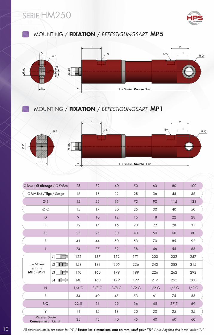
MOUNTING / FIXATION / BEFESTIGUNGSART MP5
Ø Bore / Ø Alésage / Ø Kolben 25 32 40 50 63 80 100
Ø MM Rod / Tige / Stange 16 18 22 28 36 45 56
Ø B 45 52 65 72 90 115 138
Ø C 15 17 20 25 30 40 50
D 9 10 12 16 18 22 28
E 12 14 16 20 22 28 35
EE 25 25 30 40 50 60 80
F 41 44 50 53 70 85 92
J 24 27 32 38 46 55 68
122 137 152 171 200 232 257
L + Stroke± 1mm
MP5 - MP1
158 183 205 226 243 282 315
140 160 179 199 226 262 292
140 160 179 199 217 252 280
N 1/4 G 3/8 G 3/8 G 1/2 G 1/2 G 1/2 G 1/2 G
P 34 40 45 53 61 75 88
R Q 22,5 26 29 36 45 57,5 69
Y 11 15 18 20 20 25 25
Minimum StrokeCourse min / Hub min 35 45 40 45 40 60 60
L1
L2
L3
L4
MOUNTING / FIXATION / BEFESTIGUNGSART MP1
Y L + Stroke / Course / Hub
F
J
P
Ø M
M
R QNN
Ø B
E
D
Ø C
8°
8°
Y L + Stroke / Course / Hub
F
J
P
Ø M
M
R QNN
Ø B
E
D
Ø C
8°
8°
R QØ B
EE
Ø C
J
PF
Y L + Stroke / Course / Hub
Ø M
M
N NR QØ B
EE
Ø C
J
PF
Y L + Stroke / Course / Hub
Ø M
M
N N
11
International
SERIE HM250
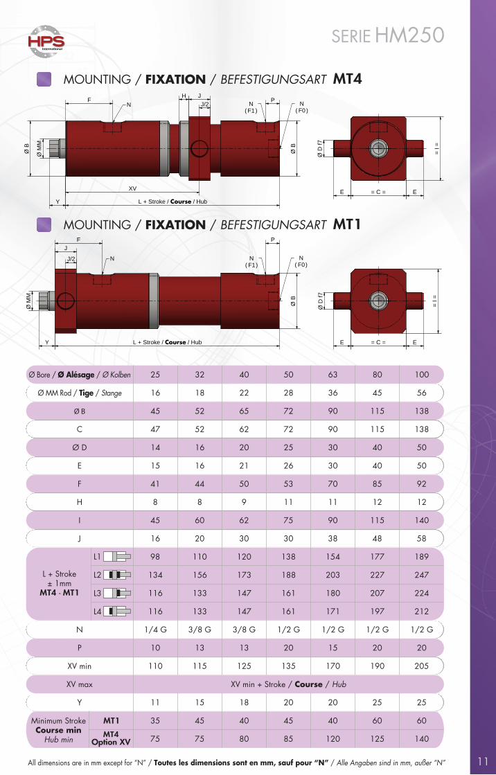
MOUNTING / FIXATION / BEFESTIGUNGSART MT4
All dimensions are in mm except for “N” / Toutes les dimensions sont en mm, sauf pour “N” / Alle Angaben sind in mm, außer “N”
Ø Bore / Ø Alésage / Ø Kolben 25 32 40 50 63 80 100
Ø MM Rod / Tige / Stange 16 18 22 28 36 45 56
Ø B 45 52 65 72 90 115 138
C 47 52 62 72 90 115 138
Ø D 14 16 20 25 30 40 50
E 15 16 21 26 30 40 50
F 41 44 50 53 70 85 92
H 8 8 9 11 11 12 12
I 45 60 62 75 90 115 140
J 16 20 30 30 38 48 58
98 110 120 138 154 177 189
L + Stroke± 1mm
MT4 - MT1
134 156 173 188 203 227 247
116 133 147 161 180 207 224
116 133 147 161 171 197 212
N 1/4 G 3/8 G 3/8 G 1/2 G 1/2 G 1/2 G 1/2 G
P 10 13 13 20 15 20 20
XV min 110 115 125 135 170 190 205
XV max XV min + Stroke / Course / Hub
Y 11 15 18 20 20 25 25
35 45 40 45 40 60 60
75 75 80 85 120 125 140
L1
L2
L3
L4
Minimum StrokeCourse min
Hub minMT4
Option XV
MT1
MOUNTING / FIXATION / BEFESTIGUNGSART MT1
Y L + Stroke / Course / Hub
J/2
JF P
Ø B
= C = EE
= I
=
Ø D
f7
N N ( F1 )
N( F0 )
Ø M
M
Y L + Stroke / Course / Hub
J/2
JF P
Ø B
= C = EE
= I
=
Ø D
f7
N N ( F1 )
N( F0 )
Ø M
M
= C =
= I
=
EE
Ø D
f7
Ø M
M
Y
XV
L + Stroke / Course / Hub
J/2
JHPF
Ø B
Ø B
N N ( F1 )
N( F0 )
= C =
= I
=
EE
Ø D
f7
Ø M
M
Y
XV
L + Stroke / Course / Hub
J/2
JHPF
Ø B
Ø B
N N ( F1 )
N( F0 )
12
International
SERIE HM250
Y L + Stroke / Course / Hub
F
Q
P
Ø D
f7
E E
NN
Ø M
M
Ø B
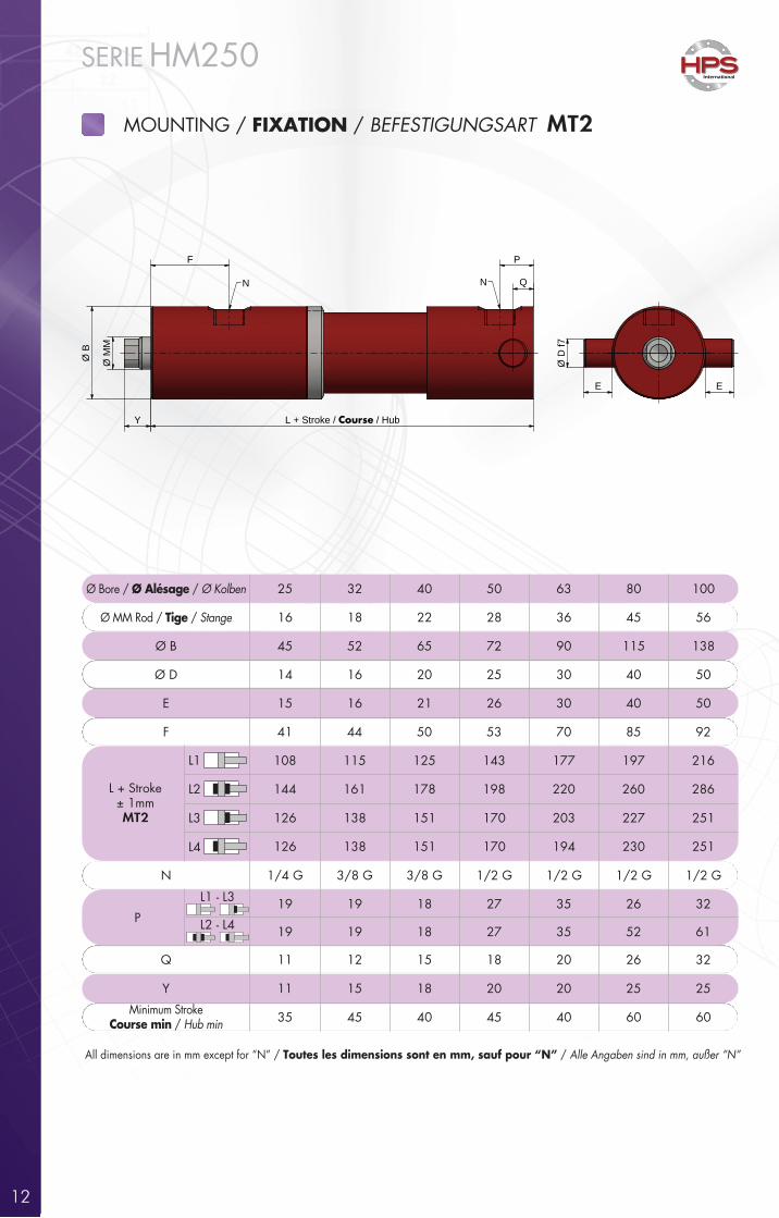
All dimensions are in mm except for “N” / Toutes les dimensions sont en mm, sauf pour “N” / Alle Angaben sind in mm, außer “N”
Ø Bore / Ø Alésage / Ø Kolben 25 32 40 50 63 80 100
Ø MM Rod / Tige / Stange 16 18 22 28 36 45 56
Ø B 45 52 65 72 90 115 138
Ø D 14 16 20 25 30 40 50
E 15 16 21 26 30 40 50
F 41 44 50 53 70 85 92
108 115 125 143 177 197 216
144 161 178 198 220 260 286L + Stroke± 1mmMT2 126 138 151 170 203 227 251
126 138 151 170 194 230 251
N 1/4 G 3/8 G 3/8 G 1/2 G 1/2 G 1/2 G 1/2 G
L1 - L3 19 19 18 27 35 26 32
L2 - L4P19 19 18 27 35 52 61
Q 11 12 15 18 20 26 32
Y 11 15 18 20 20 25 25
Minimum StrokeCourse min / Hub min 35 45 40 45 40 60 60
L1
L2
L3
L4
MOUNTING / FIXATION / BEFESTIGUNGSART MT2
13
International
SERIE HM250Ø
MM
Ø B
F F
Y L + Stroke / Course / Hub Y + Stroke / Course / Hub
Ø MM
N N
L1
L2
L3
L4
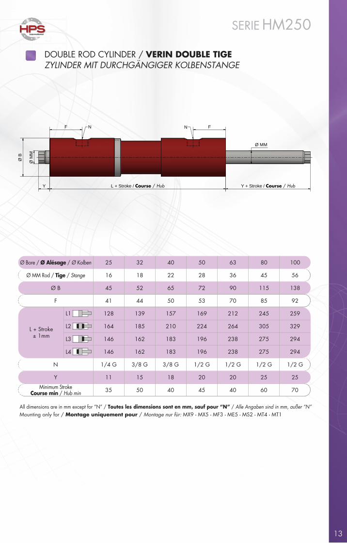
Ø Bore / Ø Alésage / Ø Kolben 25 32 40 50 63 80 100
Ø MM Rod / Tige / Stange 16 18 22 28 36 45 56
Ø B 45 52 65 72 90 115 138
F 41 44 50 53 70 85 92
128 139 157 169 212 245 259
L + Stroke± 1mm
164 185 210 224 264 305 329
146 162 183 196 238 275 294
146 162 183 196 238 275 294
N 1/4 G 3/8 G 3/8 G 1/2 G 1/2 G 1/2 G 1/2 G
Y 11 15 18 20 20 25 25
35 50 40 45 40 60 70Minimum StrokeCourse min / Hub min
DOUBLE ROD CYLINDER / VERIN DOUBLE TIGEZYLINDER MIT DURCHGÄNGIGER KOLBENSTANGE
All dimensions are in mm except for “N” / Toutes les dimensions sont en mm, sauf pour “N” / Alle Angaben sind in mm, außer “N”Mounting only for / Montage uniquement pour / Montage nur für: MX9 - MX5 - MF3 - ME5 - MS2 - MT4 - MT1
14
International
SERIE HM250
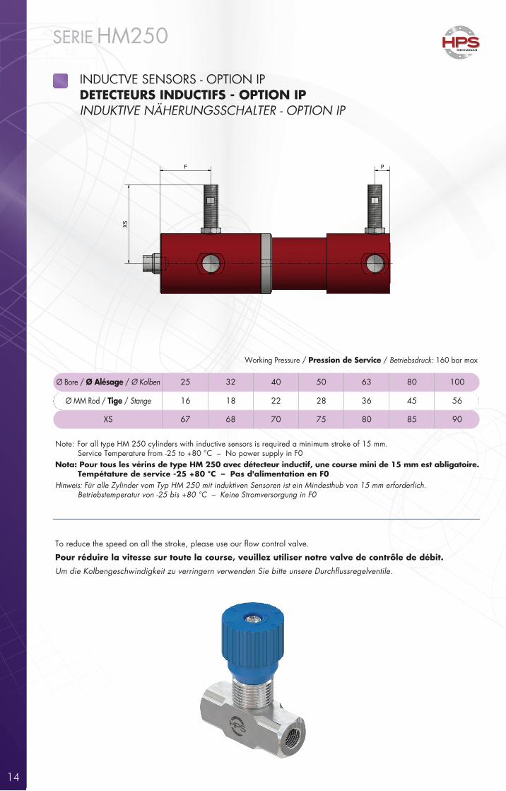
INDUCTVE SENSORS - OPTION IPDETECTEURS INDUCTIFS - OPTION IPINDUKTIVE NÄHERUNGSSCHALTER - OPTION IP
Ø Bore / Ø Alésage / Ø Kolben 25 32 40 50 63 80 100
Ø MM Rod / Tige / Stange 16 18 22 28 36 45 56
67XS 68 70 75 80 85 90
Note: For all type HM 250 cylinders with inductive sensors is required a minimum stroke of 15 mm. Service Temperature from -25 to +80 °C – No power supply in F0Nota: Pour tous les vérins de type HM 250 avec détecteur inductif, une course mini de 15 mm est abligatoire. Tempétature de service -25 +80 °C – Pas d'alimentation en F0Hinweis: Für alle Zylinder vom Typ HM 250 mit induktiven Sensoren ist ein Mindesthub von 15 mm erforderlich. Betriebstemperatur von -25 bis +80 °C – Keine Stromversorgung in F0
Working Pressure / Pression de Service / Betriebsdruck: 160 bar max
F P
XS
To reduce the speed on all the stroke, please use our �ow control valve.
Pour réduire la vitesse sur toute la course, veuillez utiliser notre valve de contrôle de débit.
Um die Kolbengeschwindigkeit zu verringern verwenden Sie bitte unsere Durchflussregelventile.
15
International
SERIE HM250
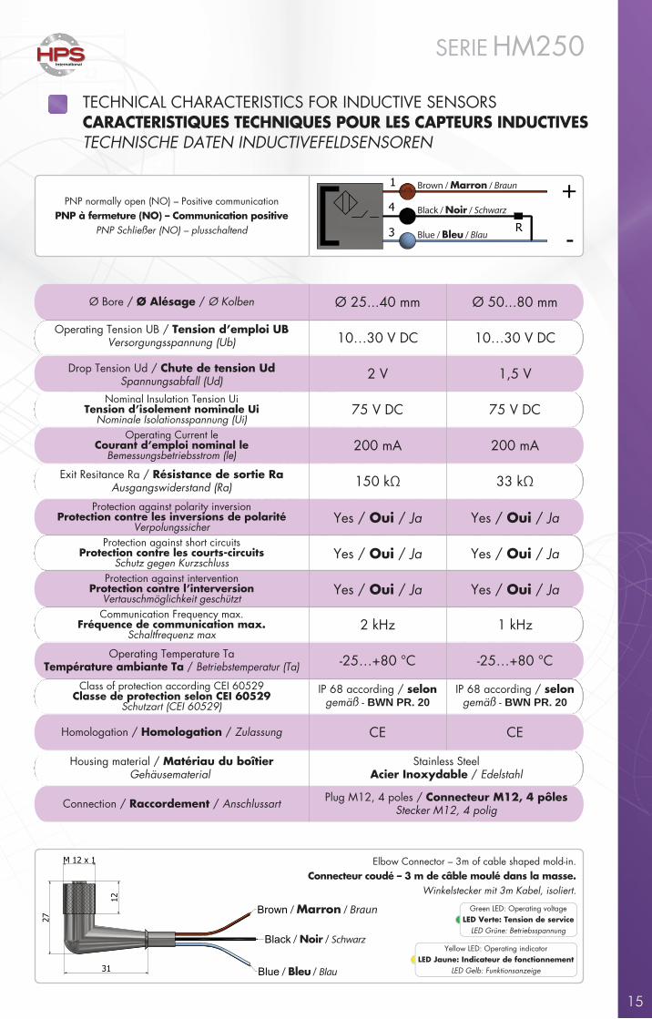
TECHNICAL CHARACTERISTICS FOR INDUCTIVE SENSORSCARACTERISTIQUES TECHNIQUES POUR LES CAPTEURS INDUCTIVESTECHNISCHE DATEN INDUCTIVEFELDSENSOREN
Operating Tension UB / Tension d’emploi UBVersorgungsspannung (Ub)
Ø 25...40 mm Ø 50...80 mm
Drop Tension Ud / Chute de tension UdSpannungsabfall (Ud)
10…30 V DC 10…30 V DC
Nominal Insulation Tension UiTension d’isolement nominale Ui
Nominale Isolationsspannung (Ui)
2 V 1,5 V
Operating Current leCourant d’emploi nominal le
Bemessungsbetriebsstrom (le)
75 V DC 75 V DC
Exit Resitance Ra / Résistance de sortie RaAusgangswiderstand (Ra)
200 mA 200 mA
Protection against polarity inversionProtection contre les inversions de polarité
Verpolungssicher
150 kΩ 33 kΩ
Yes / Oui / Ja Yes / Oui / Ja
Protection against short circuitsProtection contre les courts-circuits
Schutz gegen KurzschlussYes / Oui / Ja Yes / Oui / Ja
Protection against interventionProtection contre l’interversion
Vertauschmöglichkeit geschütztYes / Oui / Ja Yes / Oui / Ja
Communication Frequency max.Fréquence de communication max.
Schaltfrequenz max2 kHz 1 kHz
Operating Temperature TaTempérature ambiante Ta / Betriebstemperatur (Ta) -25…+80 °C -25…+80 °C
Class of protection according CEI 60529Classe de protection selon CEI 60529
Schutzart (CEI 60529)
IP 68 according / selongemäß - BWN PR. 20
IP 68 according / selongemäß - BWN PR. 20
Homologation / Homologation / Zulassung
Ø Bore / Ø Alésage / Ø Kolben
CE CE
Housing material / Matériau du boîtierGehäusematerial
Connection / Raccordement / Anschlussart Plug M12, 4 poles / Connecteur M12, 4 pôlesStecker M12, 4 polig
Stainless SteelAcier Inoxydable / Edelstahl
12M x 1
27
31
12
Brown
Black
Blue
Brown
Black
Blue R
1
4
3
+
-
/ Marron / Braun
/ Noir / Schwarz
/ Bleu / Blau
Elbow Connector – 3m of cable shaped mold-in.Connecteur coudé – 3 m de câble moulé dans la masse.
Winkelstecker mit 3m Kabel, isoliert.
PNP normally open (NO) – Positive communicationPNP à fermeture (NO) – Communication positive
PNP Schließer (NO) – plusschaltend
Brown / Marron / Braun
Black / Noir / Schwarz
Blue / Bleu / Blau
Yellow LED: Operating indicatorLED Jaune: Indicateur de fonctionnement
LED Gelb: Funktionsanzeige
Green LED: Operating voltageLED Verte: Tension de service
LED Grüne: Betriebsspannung
16
International
SERIE HM250
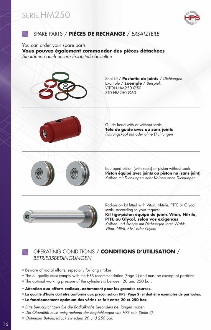
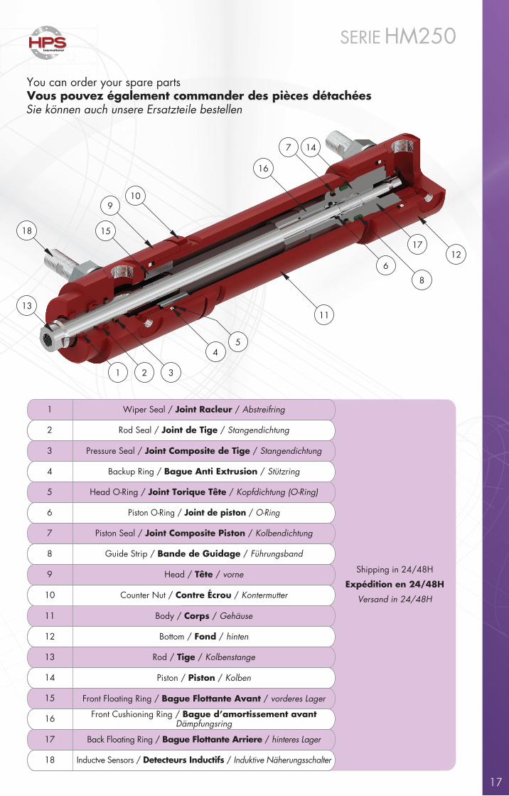
You can order your spare partsVous pouvez également commander des pièces détachéesSie können auch unsere Ersatzteile bestellen
Seal kit / Pochette de joints / DichtungenExample / Exemple / Beispiel:VITON HM250 Ø50STD HM250 Ø63
Equipped piston (with seals) or piston without sealsPiston équipé avec joints ou piston nu (sans joint)Kolben mit Dichtungen oder Kolben ohne Dichtungen
Guide head with or without sealsTête de guide avec ou sans jointsFührungskopf mit oder ohne Dichtungen
Rod-piston kit �tted with Viton, Nitrile, PTFE or Glycolseals, according to your requestKit tige-piston équipé de joints Viton, Nitrile, PTFE ou Glycol, selon vos exigencesKolben und Stange mit Dichtungen Ihrer Wahl:Viton, Nitril, PTFT oder Glycol
SPARE PARTS / PIÈCES DE RECHANGE / ERSATZTEILE
OPERATING CONDITIONS / CONDITIONS D’UTILISATION /BETRIEBSBEDINGUNGEN
Beware of radial efforts, especially for long strokes. The oil quality must comply with the HPS recommendation (Page 2) and must be exempt of particles. The optimal working pressure of the cylinders is between 20 and 250 bar.
Attention aux efforts radiaux, notamment pour les grandes courses. La qualité d’huile doit être conforme aux préconisation HPS (Page 2) et doit être exemptes de particules. Le fonctionnement optimum des vérins se fait entre 20 et 250 bar.
Bitte berücksichtigen Sie die Radialkräfte besonders bei langen Hüben. Die Ölqualität muss entsprechend der Empfehlungen von HPS sein (Seite 2). Optimaler Betriebsdruck zwischen 20 und 250 bar.
•••
•••
•••
17
International
SERIE HM250
You can order your spare partsVous pouvez également commander des pièces détachéesSie können auch unsere Ersatzteile bestellen
1 Wiper Seal / Joint Racleur / Abstreifring
Shipping in 24/48H
Expédition en 24/48H
Versand in 24/48H
2 Rod Seal / Joint de Tige / Stangendichtung
3 Pressure Seal / Joint Composite de Tige / Stangendichtung
6 Piston O-Ring / Joint de piston / O-Ring
4 Backup Ring / Bague Anti Extrusion / Stützring
Head O-Ring / Joint Torique Tête / Kopfdichtung (O-Ring)5
Head / Tête / vorne9
7 Piston Seal / Joint Composite Piston / Kolbendichtung
Guide Strip / Bande de Guidage / Führungsband8
10 Counter Nut / Contre Écrou / Kontermutter
11 Body / Corps / Gehäuse
14
12 Bottom / Fond / hinten
Rod / Tige / Kolbenstange
Piston / Piston / Kolben
Front Cushioning Ring / Bague d’amortissement avantDämpfungsring
Front Floating Ring / Bague Flottante Avant / vorderes Lager
13
Back Floating Ring / Bague Flottante Arriere / hinteres Lager17
15
16
Inductve Sensors / Detecteurs Inductifs / Induktive Näherungsschalter18
4
11
5
12
15
910
18
13
1 32
17
8
6
16
7 14
18
International
SERIE HM250
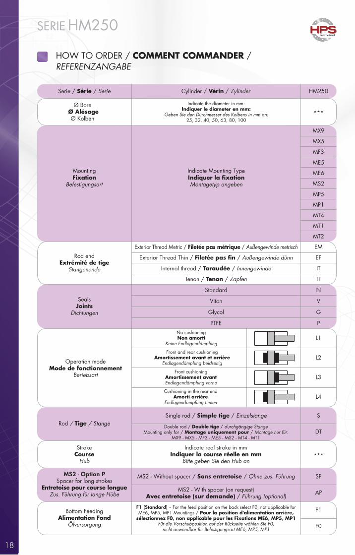
Serie / Série / Serie
Cylinder / Vérin / Zylinder HM250
Indicate the diameter in mm:Indiquer le diameter en mm:
Geben Sie den Durchmesser des Kolbens in mm an:25, 32, 40, 50, 63, 80, 100
MountingFixation
Befestigungsart
Indicate Mounting TypeIndiquer la �xationMontagetyp angeben
MX9
***
MX5
ME5
MF3
ME6
MS2
MP5
MP1
MT4
MT1
MT2
Ø BoreØ Alésage Ø Kolben
Exterior Thread Thin / Filetée pas �n / Außengewinde dünn
Internal thread / Taraudée / Innengewinde
Tenon / Tenon / Zapfen
EF
Exterior Thread Metric / Filetée pas métrique / Außengewinde metrisch EM
IT
TT
Rod endExtrémité de tige
Stangenende
Standard
Viton
N
VSealsJoints
Dichtungen Glycol G
Rod / Tige / StangeSingle rod / Simple tige / Einzelstange S
StrokeCourse
Hub
MS2 - Option PSpacer for long strokes
Entretoise pour course longueZus. Führung für lange Hübe
Indicate real stroke in mmIndiquer la course réelle en mm
Bitte geben Sie den Hub an***
PTFE P
Double rod / Double tige / durchgängige StangeMounting only for / Montage uniquement pour / Montage nur für:
MX9 - MX5 - MF3 - ME5 - MS2 - MT4 - MT1DT
Operation modeMode de fonctionnement
Beriebsart
No cushioning Non amorti
Keine EndlagendämpfungL1
Front cushioning Amortissement avantEndlagendämpfung vorne
Cushioning in the rear end Amorti arrière
Endlagendämpfung hinten
Front and rear cushioning Amortissement avant et arrière
Endlagendämpfung beidseitig
L4
L3
L2
MS2 - Without spacer / Sans entretoise / Ohne zus. Führung SP
MS2 - With spacer (on request)Avec entretoise (sur demande) / Führung (optional)
AP
Bottom FeedingAlimentation Fond
Ölversorgung
F1 (Standard) - For the feed position on the back select F0, not applicable forME6, MP5, MP1 Mountings / Pour la position d'alimentation arrière,
sélectionnez F0, non applicable pour les Fixations ME6, MP5, MP1Für die Vorschubposition auf der Rückseite wählen Sie F0,
nicht anwendbar für Befestigungsart ME6, MP5, MP1
F1
F0
HOW TO ORDER / COMMENT COMMANDER /REFERENZANGABE
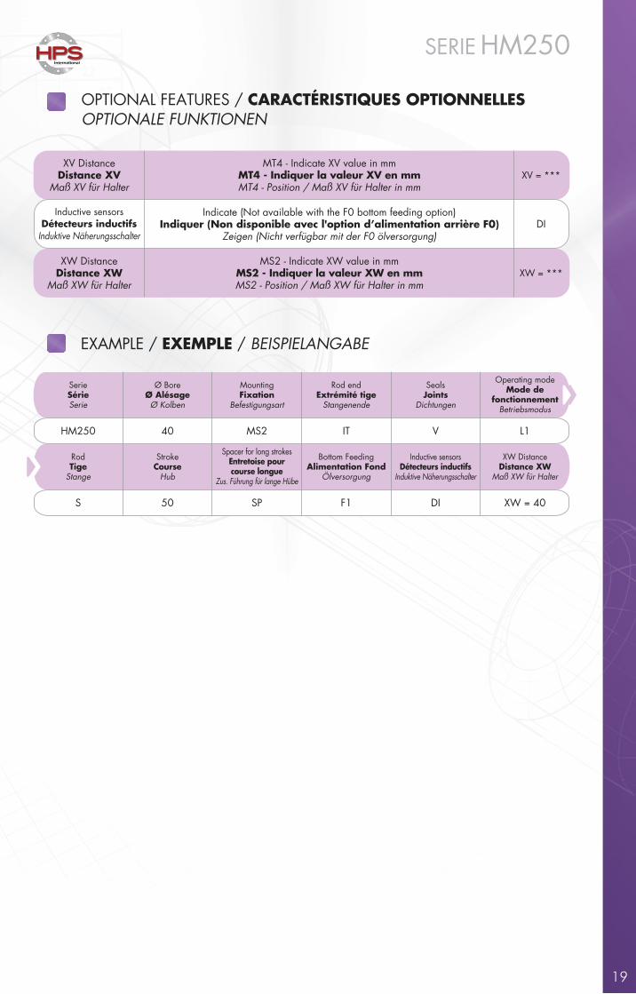
XW DistanceDistance XW
Maß XW für Halter
MS2 - Indicate XW value in mmMS2 - Indiquer la valeur XW en mmMS2 - Position / Maß XW für Halter in mm
XW = ***
XV DistanceDistance XV
Maß XV für Halter
MT4 - Indicate XV value in mmMT4 - Indiquer la valeur XV en mmMT4 - Position / Maß XV für Halter in mm
XV = ***
International
SERIE HM250
OPTIONAL FEATURES / CARACTÉRISTIQUES OPTIONNELLESOPTIONALE FUNKTIONEN
19
Inductive sensorsDétecteurs inductifs
Induktive Näherungsschalter
Indicate (Not available with the F0 bottom feeding option)Indiquer (Non disponible avec l'option d’alimentation arrière F0)
Zeigen (Nicht verfügbar mit der F0 ölversorgung)DI
EXAMPLE / EXEMPLE / BEISPIELANGABE
SerieSérieSerie
Ø BoreØ AlésageØ Kolben
MountingFixation
Befestigungsart
Rod endExtrémité tige
Stangenende
SealsJoints
Dichtungen
Operating modeMode de
fonctionnementBetriebsmodus
HM250 40 MS2 IT V L1
StrokeCourse
Hub
Spacer for long strokesEntretoise pourcourse longue
Zus. Führung für lange Hübe
Bottom FeedingAlimentation Fond
Ölversorgung
Inductive sensorsDétecteurs inductifs
Induktive Näherungsschalter
XW DistanceDistance XW
Maß XW für Halter
50 SP F1 DI XW = 40
RodTige
Stange
S
20
International
SERIE HM250
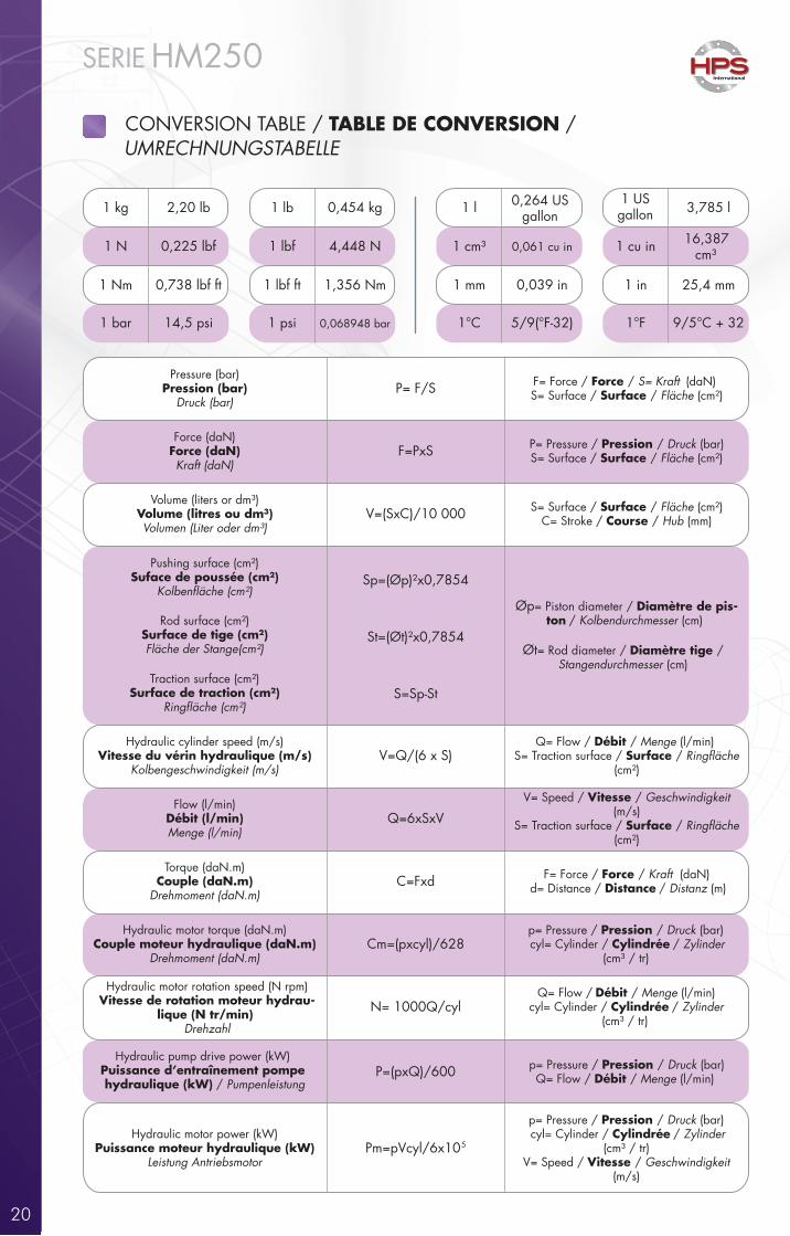
CONVERSION TABLE / TABLE DE CONVERSION /UMRECHNUNGSTABELLE
Pressure (bar)Pression (bar)
Druck (bar)
Force (daN)Force (daN)Kraft (daN)
Volume (liters or dm³)Volume (litres ou dm³)Volumen (Liter oder dm³)
Pushing surface (cm²)Suface de poussée (cm²)
P= F/S
Rod surface (cm²)Surface de tige (cm²)Fläche der Stange(cm²)
Traction surface (cm²)Surface de traction (cm²)
Hydraulic cylinder speed (m/s)Vitesse du vérin hydraulique (m/s)
Kolbengeschwindigkeit (m/s)
Flow (l/min)Débit (l/min)Menge (l/min)
Torque (daN.m)Couple (daN.m)
Drehmoment (daN.m)
Hydraulic motor torque (daN.m)Couple moteur hydraulique (daN.m)
Drehmoment (daN.m)
Hydraulic motor rotation speed (N rpm)Vitesse de rotation moteur hydrau-
lique (N tr/min)Drehzahl
Hydraulic pump drive power (kW)Puissance d’entraînement pompe hydraulique (kW) / Pumpenleistung
Hydraulic motor power (kW)Puissance moteur hydraulique (kW)
Leistung Antriebsmotor
F=PxS
V=(SxC)/10 000
Sp=(Øp)²x0,7854
St=(Øt)²x0,7854
S=Sp-St
V=Q/(6 x S)
Q=6xSxV
C=Fxd
Cm=(pxcyl)/628
N= 1000Q/cyl
P=(pxQ)/600
Pm=pVcyl/6x105
F= Force / Force / S= Kraft (daN)S= Surface / Surface / Fläche (cm²)
P= Pressure / Pression / Druck (bar)S= Surface / Surface / Fläche (cm²)
S= Surface / Surface / Fläche (cm²)C= Stroke / Course / Hub (mm)
Øp= Piston diameter / Diamètre de pis-ton / Kolbendurchmesser (cm)
Øt= Rod diameter / Diamètre tige / Stangendurchmesser (cm)
Q= Flow / Débit / Menge (l/min)S= Traction surface / Surface /
(cm²)
V= Speed / Vitesse / Geschwindigkeit (m/s)
S= Traction surface / Surface / (cm²)
F= Force / Force / Kraft (daN)d= Distance / Distance / Distanz (m)
p= Pressure / Pression / Druck (bar)cyl= Cylinder / Cylindrée / Zylinder
(cm³ / tr)
Q= Flow / Débit / Menge (l/min)cyl= Cylinder / Cylindrée / Zylinder
(cm³ / tr)
p= Pressure / Pression / Druck (bar)Q= Flow / Débit / Menge (l/min)
p= Pressure / Pression / Druck (bar)cyl= Cylinder / Cylindrée / Zylinder
(cm³ / tr)V= Speed / Vitesse / Geschwindigkeit
(m/s)
1 US gallon 3,785 l
1 cu in 16,387 cm³
1 in 25,4 mm
1°F 9/5°C + 32
1 cm³ 0,061 cu in
1 lbf ft 1,356 Nm
1 psi 0,068948 bar 1°C 5/9(°F-32)
1 Nm 0,738 lbf ft
1 bar 14,5 psi
1 N 0,225 lbf 1 lbf 4,448 N
1 kg 2,20 lb 1 lb 0,454 kg 1 l 0,264 US gallon
1 mm 0,039 in

International
SERIE HM250
21
NOTES

22
www.hpsinternational.com/en/worldwide
ASIA LIMITED
INDIA
MERCOSUL
NORTH AMERICA
PORTUGAL
HPS JARRY, LDARua Alcorredores - Edifício Onix - Fração E
3020-923 Torre De Vilela - PORTUGALTel : +351 239 910 030
Email : [email protected]
ITALIA
HPS ITALIAVia S. Lucia, 9 - 24128 Bergamo - ITALIA
Tel: +39 035 063 0962Email : [email protected]
UnitedKingdom
Turkiye
Ireland
Romania
SouthKorea
NorthKorea
Taiwan
Japan
Mongolia
Russia
HPS MERCOSULRua Maria Antónia C Ribeiro Dos Santos N°63
CEP. 13086-746 Campinas - SP BrazilTel: +55 19 3257 2039
Email : [email protected]
HPS INDIAShop n° 6, Morya Industrial Complex,
T-201/1, Midc Bhosari411026 Pune
Maharashtra - INDIATel : +91 9970124713
Email : [email protected]
HPS ASIA / HPS SHENZEN LIMITEDFloor 1, Industrial Building 2, Furong 7th Rd
Furong Industrial Zone, Shajin St, 518103 Bao'an District - Shenzhen, Guangdong
CHINATel: +86 755 2917 8531Fax: +86 755 2903 4152
Email : [email protected]
HPS NORTH AMERICA2850 Jefferson Blvd - Windsor,Ontario - N8T 3J2
Tel: +1 226 674 4256Email : [email protected]
Morocco
HYDROPNEUPartner für Hydraulik
HYDROPNEU GmbHSudetenstraße 1 D - 73760 Ostfildern
Tel: +49 7113 42 99 90Fax: +49 7113 42 99 91
Email : [email protected]
POLSKA
HP SYSTEMS POLSKAWojska Polskiego 2APL 05-220 Zielonka
Tel: +48 226 143 411 Email : [email protected]
In CZECH Rep
HPS In CZECH REPUBLICNáměstí Svaté Hedviky 2232/18
746 01 OpavaTel: 00420/737 209 730
Email : [email protected]
FRANCE
HEADQUARTERS:HYDRAULIQUE PRODUCTION SYSTEMS
62, chemin de la Chapelle Saint-AntoineZ.A.C.- 95300 Ennery - FRANCE
Tel : +33 134 353 838Fax : +33 130 750 808
Email : [email protected]
In TURKIYE
HPS In TURKIYETeori Engineering and Consultancy
Akse Mah. 69. sok. Park Panorama Rezidans No:77/33Cayirova - Kocaeli - TURKEY
Tel: +905054946938 - Sinan SutcuEmail : [email protected]
SLOVAKIA
HPS SLOVAQUIE S.R.OLOCAL PARTNER: VALEX
NOBELOVA 34836 05 BRATISLAVA - SK
Tel: +421 904 288 203Email : [email protected]
ACIM Hydro1, rue des VAB 42400 Saint Chamond
Tel : +33 477 366 688Email : [email protected]
www.acimhydro.fr
Main contact / Contact principalHauptkontakt
2D/3D Data
Quotation / Devis / Anfrage
Replace cylinders / Remplacement devérins / Ersatzzylinder
Speci�c cylinders / Vérins spéci�quesSpezialzylinder
We are present in 26 countries / Nous sommesprésents dans 26 pays / Wir sind in 26
Ländern vertreten : Argentina, Brazil, Canada,Czech Republic, China, France, Germany,Hong Kong, India, Italy, Japan, Mexico,
Morocco, Poland, Portugal, Romania, Russia,Slovakia, South Africa, South Korea, Spain, Taiwan,
Thailand, Turkey, United Kingdom, and USA.
TECHNICAL & COMMERCIAL REQUESTDEMANDES TECHNIQUES & COMMERCIALES / ANFRAGEN
HPS MEXICANAQuerétaro:
Avenida del Marqués No. 37,Parque Industrial Bernardo Quintana;
El Marqués, Querétaro; zip code 76246Office: +52 81 40405009
Email : [email protected]
Monterrey:Torreón 321,
Mitras Centro Monterrey N.L.zip code 64460
Office: +52 81 40405009Email : [email protected]
MEXICO