i · 2014-10-26 · weighted s/n ratio to din 45 590 maximal spl powering operating volt3ge current...
TRANSCRIPT

."
~-o~~H)l1I\I-_O~~H)l1I\I
IOldw3,Papolf\Iapln~sJaSn
6unllalues6unualpas
H:I~I:IHNN:I~::Qj:::,.1
SPEZIAL-MIKROFONEMKH110 UND MKH 110-1
Kurzbeschreibung
TECHNISCHE HINWEISE
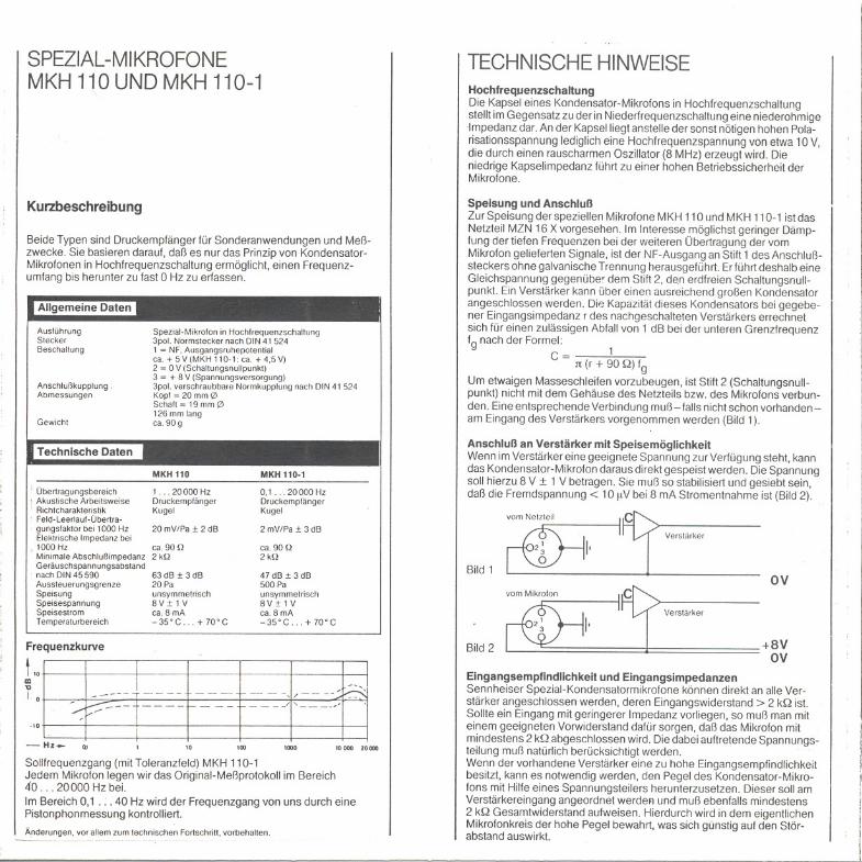
HochfrequenzschaltungDie Kapsel eines Kondensator-Mikrofons in Hochfrequenzschaltungstellt im Gegensatz zu der in Niederfrequenzschaltung eine niederohmigeImpedanz dar. An der Kapsel liegt anstelle der sonst nötigen hohen Pola-risationsspannung lediglich eine Hochfrequenzspannung von etwa 10 V,die durch einen rauscharmen Oszillator (8 MHz) erzeugt wird. Dieniedrige Kapselimpedanz führt zu einer hohen Betriebssicherheit derMikrofone.
Speisung und AnschlußZur Speisung der speziellen Mikrofone MKH 110 und MKH 110-1 ist dasNetzteil MZN 16 X vorgesehen. Im Interesse möglichst geringer Dämp-fung der tiefen Frequenzen bei der weiteren Übertragung der vomMikrofon gelieferten Signale, ist der NF-Ausgang an Stift 1des Anschluß-steckers ohne galvanische Trennung herausgeführt. Erführt deshalb eineGleichspannung gegenübe' dem Stift 2, den erdfreien Schaltungsnullepunkt. Ein Verstärker kann über einen ausreichend großen Kondensatorangeschlossen werden. Die Kapazität dieses Kondensators bei gegebe-ner Eingangsimpedanz r des nachgeschalteten Verstärkers errechnetsich für einen zulässigen Abfall von 1 dB bei der unteren Grenzfrequenzfg nach der Formel:
c= 11t (r + 90 Q) fg
Um etwaigen Masseschleifen vorzubeugen, ist Stift 2 (Schaltungsnull-punkt) nicht mit dem Gehäuse des Netzteils bzw. des Mikrofons verbun-den. Eine entsprechende Verbindung muß - falls nicht schon vorhanden-am Eingang des Verstärkers vorgenommen werden (Bild 1).
Beide Typen sind Druckempfänger für Sonderanwendungen und Meß-zwecke. Sie basieren darauf, daß es nur das Prinzip von Kondensator-Mikrofonen in Hochfrequenzschaltung ermöglicht, einen Frequenz-umfang bis herunter zu fast 0 Hz zu erfassen.
Allgemeine Daten
AusführungSteckerBeschalfung
AnschlußkupplungAbmessungen
Gewicht
Spezial-Mikrofon in Hochfrequenzschaltung3pot. Normstecker nach DIN 41 5241 = NF.Ausgangsruhepotentialca. + 5 V(MKH 110-1: ca. + 4,5 V)2 = 0 V (Schaltungsnullpunkt)3 = + 8 V (Spannungsversorgung)3pot. verschraubbare Normkupplung nach DtN 41 524Kopf = 20mm 0Schaft ~ 19 mm 0126 mm langca. 90 9
Technische Daten Anschluß an Verstärker mit SpeisemöglichkeitWenn im Verstärker eine geeignete Spannung zur Verfügung steht, kanndas Kondensator-Mikrofon daraus direkt gespeist werden. Die Spannungsoll hierzu 8 V :t 1 V betragen. Sie muß so stabilisiert und gesiebt sein,daß die Fremdspannung< 10 IlV bei 8 mA Stromentnahme ist (Bild 2).
-- Hz- Q'
, ObertragungsbereichAkustische ArbeitsweiseRichtcharakteristikFeld-Leerlauf-Obertra-
. gungstaktorbei 1000 HzElektrische Impedanz bei
, 1000 HzMinimaleAbschlußimpedanzGeräuschspannungsabstandnach DIN 45 590AussteuerungsgrenzeSpeisungSpeisespannungSpeisestromTemperafurbereich
Frequenzkurve
MKH 110
1...20000HzDruckempfängerKugel
20 mV/Pa:!: 2 dB
ca. 90 Q2kQ
63 dB :!:3 dB20Paunsymmetrisch8V:!:lVca. 8 mA-35'C. . + 70'C
10
MKH 110.1
0,1.. .20000 HzDruckempfängerKugel
+8VOV
2 mV/Pa:!: 3 dBVerstärker
ca. 90 Q2kQ
47 dB :!:3 dB500 Paunsymmetrisch8V:!: 1 Vca. 8 mA-35'C. . + 70'C
Bild 1OV
Verstärker
Bild 2
100
Eingangsempfindlichkeit und EingangsimpedanzenSennheiser Spezial-Kondensatormikrofone können direkt an alle Ver-stärker angeschlossen werden, deren Eingangswiderstand> 2 kQ ist.Sollte ein Eingang mit geringerer Impedanz vorliegen, so muß man miteinem geeigneten Vorwiderstand dafür sorgen, daß das Mikrofon mitmindestens 2 kQ abgeschlossen wird. Die dabei auftretende Spannungs-teilung muß natürlich berücksichtigt werden.Wenn der vorhandene Verstärker eine zu hohe Eingangsempfindlichkeitbesitzt, kann es notwendig werden, den Pegel des Kondensator-Mikro-fons mit Hilfe eines Spannungsteilers herunterzusetzen. Dieser soll amVerstärkereingang angeordnet werdeFl und muß ebenfalls mindestens2 kQ Gesamtwiderstand aufweisen. Hierdurch wird in dem eigentlichenMikrofonkreis der hohe Pegel bewahrt, was sich günstig auf den Stör-abstand auswirkt.
I! I! I
11I.
I
1000 10 000 10000
Sollfrequenzgang (mit Toleranzfeld) MKH110-1Jedem Mikrofon legen wir das Original-Meßprotokoll im Bereich40. . . 20000 Hz bei.
Im Bereich 0,1 . - - 40 Hz wird der Frequenzgang von uns durch einePistonphonmessung kontrolliert.
-~-----_.._------Änderungen, vor allem zum technischen Fortschritt, vorbehalten.

INSTRUMENTATIONMICROPHONESMKH110ANDMKH110-1
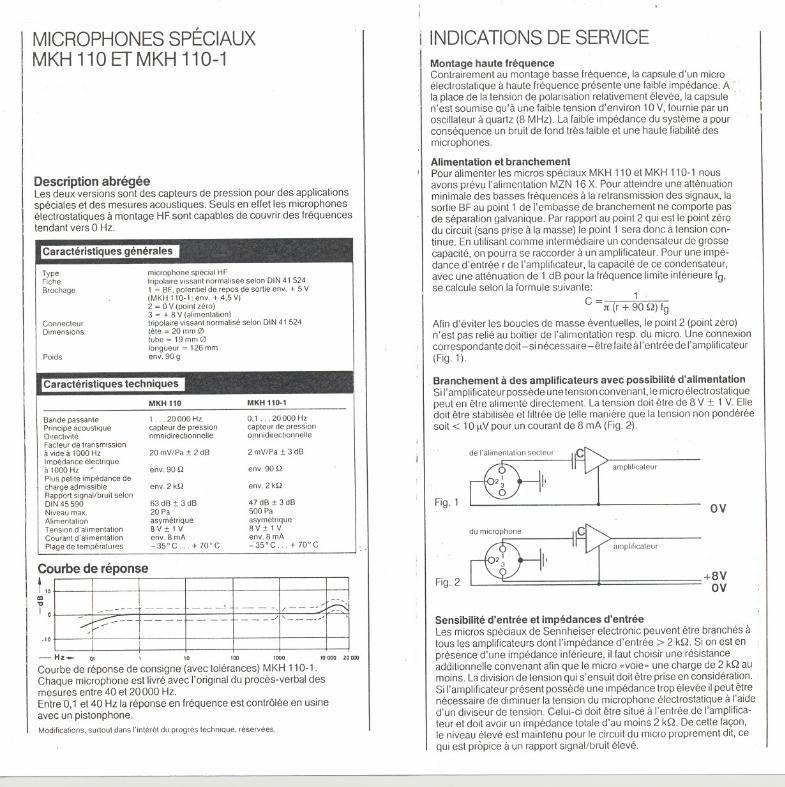
Short DescriptionThese microphones are especially designed pressure transducers lorinstrumentation purposes. Only the operating principle 01RF-condensermicrophones allows a Irequency response to extend down to 0 Hz.
DescriptionOutputplugWlring
special microphone in RF-technique3-pln connector to DIN 41 5241 = audio. nominal circuit output voltageappx. + 5 V(MKH 110-1: appx. + 4.5 V)2 = 0 V(cireuit ground)3 = + 8 V (voltagesupply)3-pin standardeonneetor10DIN41 524Head = 20 mm 0Tube = 19 mm 0Length 126 mmappx. 90 9
Cable conneclorDimensions
Weight
Technical Data
FrequeneyresponseAcoust:ealmode 01operationDireetionaleharacteristieSensilivityat 1000 HzEleetriealimpedanceal 1000 HzMinimal load impedaneeWeighted S/N ratio toDIN 45 590MaximalSPLPoweringOperatingvolt3geCurrent drawnTemperalure range
MKH110
1.. 20000 Hzpressure transduceromnidireelional20 mV/Pa:t 2 dB
MKH 110-1
0.1...20000Hzpressure transduceromnidireetional2mV/Pa:t3aB
appx. 90 Q2kQ
appx. 90 Q2kQ
63 dB :t 3 dB20 Paunbalaneed8V:t1Vappx. 8 mA-35'C . + 70'C
47dB:t 3dB500 Paunbalaneed8V:t 1Vappx. 8 mA-35'C. . + 70'C
Frequency Response
~.:Ek~.~-~~~t~--l~.~I:~~~~- Hz- QI I 10 100 1000 10000 '0000
Standard Irequency response with tolerance limits MKH 110-1.The original diagram is delivered with each microphone 01this type,measured lrom 40 to 20000 Hz.The Irequency response in the range 010.1 Hz to 40 Hz is checked witha piston-phone by uso
We reserve the fight to alter specitications. in partieularwith regard to technieallmprove-menls.
TECHNICALNOTESHigh Frequency CircuitThe capsule 01a RF-condenser microphone presents, contrary tolow Irequency circuits, a low impedance output. Instead 01the highpolarization voltage normally required, a high Irequency capsule needsonly a high Irequency voltage 01about 10 V, wh ich is produced by abuilt-in low noiseoscillator(8 MHz).The low capsule impedance leads 10a high perlormance reliability 01the microphones.
Powering and ConnectionFor powering the special microphones MKH 110 and MKH 110-1 acorresponding power supply MZN 16 X is provided. In order that theIrequency response cannot be limited by the value 01the output couplingcapacitor, the audio output on pin 1 01the microphone is connecteddirectly to the output amplifier without a blocking capacitor. There is,therelore, a DC-voltage on this pin against ground. An amplilier may beconnected using a corresponding capa citor. With a given amplilier inputimpedance rand the -1 dS point at the lower Irequency limit Ig, the
capacitor value is determinated by the lormula: 1C-
. - Jt (r + 90 Q) Ig .
:To prevent ground loops, pin 2 (circuit ground) is not connected with the, housing 01the power supply respectively the microphone. Acorres-ponding connection - il not already incorporated - has to be providep(Fig.1).
IiI
: I
Connection to Amplifiers with Powering Facilities11an appropriate voltage source is available in the amplilier the condensermicrophone can be powered directly. The voltage should be 8 V :t 1 V.It should be so stabilised and liltered, that the unweighted noise voltageis< 10 ftV at 8 mA current consumption (Fig. 2).
:'
Irom power supply
ovFig.1
.~.
2~ I'I(QJIamplifter
Fig.2 +8VOV
amplrller
Input Sensitivity and Input Impedance'Sennheiser special condenser microphones can be connected directly toall amplifiers whose input impedance is > 2 kQ. 11the input impedance islower, a resistor 01appropriate value should be placed in series with themicrophone to provide correct matching. The voltage division caused bythis series resistor must 01course be considered.11the amplilier being used has a too high input sensitivity, it can be
I
' necessary to reduce the output voltage Irom the microphone by means 01i a voltage divider. This should be built at the amplilier input and must have
a total impedance 01at least 2 kQ. Sy this means the large signal on the
I microphone cable is maintained up to just belore the amplilier, wh ichhelps to increase the signal to noise ratio.
MICROPHONESSPECIAUXMKH 110 ET MKH 110-1
Description abregeeLes deux versions sont des capteurs de pression pour des applicationsspeciales et des mesures acoustiques. Seuls en effet les microphoneselectrostatiques a montage HF sont capables de couvrir des frequencestendant vers 0 Hz.
Caracteristiques generales
TypeFicheBroehage
ConneeteurOimensions
Poids
mierophone special HFtnpolalre vlssant normalisee selon DIN 41 5241 = BF.potentiel de repos de sortie env. + 5 V(MKH 110.1: env. + 4.5 V)2 = 0 V(point zero)3 = + 8 V (alimentation)tripolaire vissant normalise selon DIN 41 524tete = 20 mm 0tube=19mm0longueur = 126 mmenv. 90 g
Caracteristiques techniques
MKH110 MKH 110-1
Bande passantePrineipeaeoustiqueDireetivlteFaeteurde transmissiona vide a 1000 HzImpedaneeeleetriquea1000Hz -Pluspetite impedaneedecharge admissibleRapportsignal/bruit selonDIN 45590Niveau max.AlimentationTension d'alimentationCourant d'alimentationPlagede temperatures
1. .20000Hzeapteurde pressionomnidireetlonnelle
0.1.. 20000 Hzeapteurde pressionomnidirectionnelle
20 mV/Pa :t 2 dB 2 mV/Pa :t 3 dB
env. 90 Q env. 90 Q
env. 2 kQ env. 2 kQ
63 dB :t 3 dB20 Paasymetrique8V:t1Venv. 8 mA-35°C. + 70°C
47dB:t3dB500 Paasymetrique8V:t 1 Venv. 8 mA-35°C. . + 70°C
~~l==~l.~~=--~:l==~~-Hz- ~I 10 100 1000 '0000 20 000
Courbe de reponse de consigne (avec tolerances) MKH 110-1 .Chaque microphone est livre avec I'original du proces-verbal desmesures entre 40 et 20000 Hz.Entre 0,1 et 40 Hz la reponse en frequence est contrölee en usineavec un pistonphone.Modllieations.surtout dans I'interet du progres teehnique. reservees.
i INOICATIONSOESERVICE
It
Montage haute frequenceContrairement au montage basse frequence, la capsule d'unmicroelectrostatique a haute frequence presente une faible impedance. Ala place de la tension de polarisation relativement elevee, la capsule .,
n'est soumise qu'a une faible tension d'environ 10 V,foumie par unoscillateur a quartz (8 MHz).La faible impedance du systeme a pourconsequence un bruit de fond tres faible et une haute fiabilitedesmicrophones.
Alimentation et branchementPour alimenter les micros speciaux MKH 110 et MKH 110-1 nousavons prevu I'alimentation MZN 16 X. Pour atteindre une attenuationminimale des basses frequences a la retransmission des signaux, lasortie BF au point 1 de I'embasse de branchement ne comporte pasde separation galvanique. Par rapport au point 2 qui est le point zerodu circuit (sans prise a la masse) le point 1 sera donc a tension con-tinue. En utilisant comme intermediaire un condensateur de grossecapacite, on pourra se raccorder a un amplificateur. Pour une impe-dance d'entree r de I'amplificateur, la capacite de ce condensateur,avec une attenuation de 1 dB pour la frequence limite inlerieure Ig,se calcule selon la formule suivante:
1
C = Jt (r + 90 Q) fgAfin d'eviter les bouGIes de masse eventuelles, le point 2 (point zero)n'est pas relie au boitier de I'alimentation resp. du micro. Une connexioncorrespondante doit - si necessaire -etre faite a I'entree de I'amplificateur(Fig.1).
Branchement ades amplificateurs avec possibilite d'alimentationSi I'amplificateur possede une tension convenant, le micro electrostatiquepeut en etre alimente directement. La tension doit etre de 8 V :!::1 V. Elledoit etre stabilisee et filtree de teile maniere que la tension non pondereesoit< 10 ftV pour un courant de 8 mA (Fig. 2').
Fig.1 ov
ampliliealeur
Fig.2+8V
OV
amplilieateur
Sensibilite d'entree et impedances d'entree
Les micros speciaux de Senn heiser electronic peuvent etre branches atous les amplilicateurs dont I'impedance d'entree > 2 kQ. Si on est enpresence d'une impedance inferieure, iI faut choisir une resistanceadditionnelle convenant afin que le micro «voie.. une charge de 2 kQ aumoins. La division de tension qui s'ensuit doit etre prise en consideration.Si I'amplificateur present possede une impedance trop elevee il peut etrenecessaire de diminuer la tension du microphone electrostatique a I'aided'un diviseur de tension. Celui-ci doil etre situe a I'entree de I'amplifica-teur et doit avoir un impedance totale d'au moins 2 kQ. De cette fayon,le niveau eleve est mainteou pour le circuit du micro proprement dit, cequi est propice a un rapport signal/bruit eleve.
~
IIIII
II
I
,
I
It
I
I,
I
II
SENNHEISERELECTRONICKG0-3002 WEOEMARKTELEFON05130/600-0TELEX924623TELEFAX05130/6312