manual - · pdf file1. the input section the dtc™ has a comprehensive input section...
TRANSCRIPT
MANUALw
ww
.min
dpri
nt.c
om
MANUAL
1.1
EN
GL
ISH
DE
UT
SC
H

Important:Please read safety instructions (on page 32) before use!
Wichtig:Bitte lesen Sie vor der Inbetriebnahme die Sicherheits-hinweise auf Seite 32!
MindPrint-DTCTM
Welcome!Today the secret of “expensive” sound no longer lies in tape machines orcostly mixing consoles. The key to unlocking the secret of sophisticatedsound and getting top-notch tone in the can is translating all theintricacies of signals into the digital world. And that, in a nutshell, is what the new MindPrint® DTC™ does.
The MindPrint Dual Tube Channel signal processor combines two high-quality microphonepreamps, equalizers and compressor/limiters in one unit, giving you all the functionality of afully-loaded high-end channel strip. Its unique pairing of tried-and-true analog componentswith the audio fidelity of today’s advanced circuit designs will lend your recordingsunparalleled vividness and warmth. And with the optional digital interface in place, the DTC™ will seamlessly fit into your digital studio environment.
The people who have joined forces to comprise the MindPrint team share years of experiencefrom the fields of pro audio, tube circuitry, and digital technology. In this new MindPrintproduct, they have applied their collective know-how to meet the expressed wishes of countless studio engineers the world over.
Over the past several years, modern recording equipment has achieved a very high level ofquality at continually improving prices. Often, however, much of the real potential of therecording is unfortunately lost due to inadequacies at either the input stage, the digitalconversion stage, or the analog circuitry used around the converter.
The DTC™ provides precisely this missing link in the signal chain, delivering those very elements and features that bring out the best of your other recording equipment. The resulting sound is more dimensional, more vivid and more truly musical.
One of the underlying design principles behind the DTC™ is optimization of the signal paths.In each and every design decision the shortest possible signal path was chosen, bypassingunneeded components completely.
All in all, the very effective filtering, the opto/tube-compressor and the optional digital inputsand outputs (24-bit/96 kHz) combine to make the DTC™ a universal processing center forevery kind of audio signal.
We wish you a great deal of enjoyment and success with your new DTC™!
St. Wendel, GermanyDecember 2001
3
MindPrint-DTCTM
INFOIn the digital age achieving a higher level of quality issomething that is nearly impossible to do with justhigher sampling rates or bit depths. Digitalprocessing quality is better than ever, and hasreached a level (with the new DVD standard) thatmeets even the highest sonic and dynamicrequirements. With a sampling rate of 96 kHz we canreproduce frequencies that are more than double thehighest frequencies man's hearing mechanism iscapable of perceiving. A resolution of 24 bits offers usa dynamic range that can capture sound at pressurelevels that go far beyond the threshold of pain ofhuman hearing. In the past, our attempt toreproduce all the perceptible nuances of a sound wasseverely limited by the available technology; todaywe are much closer to capturing all the details of asound in its full glory.
QUESTION: Since digital technology today is capableof such high resolution, one would think that the bestand shortest connection would be a pure analog-to-digital converter. So why is MindPrint nowdeveloping high-end analog technology?
ANSWER: Even more important than the quality ofthe digital converter itself is the quality of the analogcircuitry preceding the converter. Today the only partof the signal chain that is subject to loss is the analogsection that prepares the signal right before it hitsthe digital realm. The task of the DTC™ is to makethis part of the path as good and as short as possible. The thing to keep in mind is that the sound ofinstruments and microphones occur in the analogrealm, as waves and current, and not as bits andsamples. And waves and current are very sensitive asto how they react to physical quantities such asimpedance, capacitance, and induction. And onlywhen we pay proper attention to these quantities,and waves and current are turned into the "rightform," do we stand a good chance of performing aproper conversion to digital. Technically speaking, thejob of the DTC™ is to take a very weak modulatingelectrical signal with a very broad frequency rangeand amplify it and "shape" it. But this electrical signalhas its own peculiarities: depending on whether theinduction and the capacitance is set up in the circuitto run in parallel or in series, these can have adamping effect on the bass and treble. With allanalog sound sources, whether pickup ormicrophone, or even a normal cable, the capacitanceand inductance play a role and influence the sound.The special input circuitry of the DTC™ respects themin a very special way, so that they do have thenecessary "raw form" required for the subsequentfrequency and dynamics processing.
EN
GL
ISH
Table of Contents:
1. The Input . . . . . . . . . . . . . . . . . . . . . . . . . . . . . . . . . 62. Equalization: Frequency Processing . . . . . . . . . . . . . 103. Compressor/Limiter: Dynamics Processing. . . . . . . . 144. The Output . . . . . . . . . . . . . . . . . . . . . . . . . . . . . . . 175. Technical Specifications . . . . . . . . . . . . . . . . . . . . . . 186. Appendix: The Digital Option . . . . . . . . . . . . . . . . . 19
1. The Input Section
The DTC™ has a comprehensive input sectionconsisting of a line-level input, an instrumentinput and a microphone input. You can add a digital input by installing the MindPrint DI-Mod 24/96 expansion module.
1.1 Microphone input
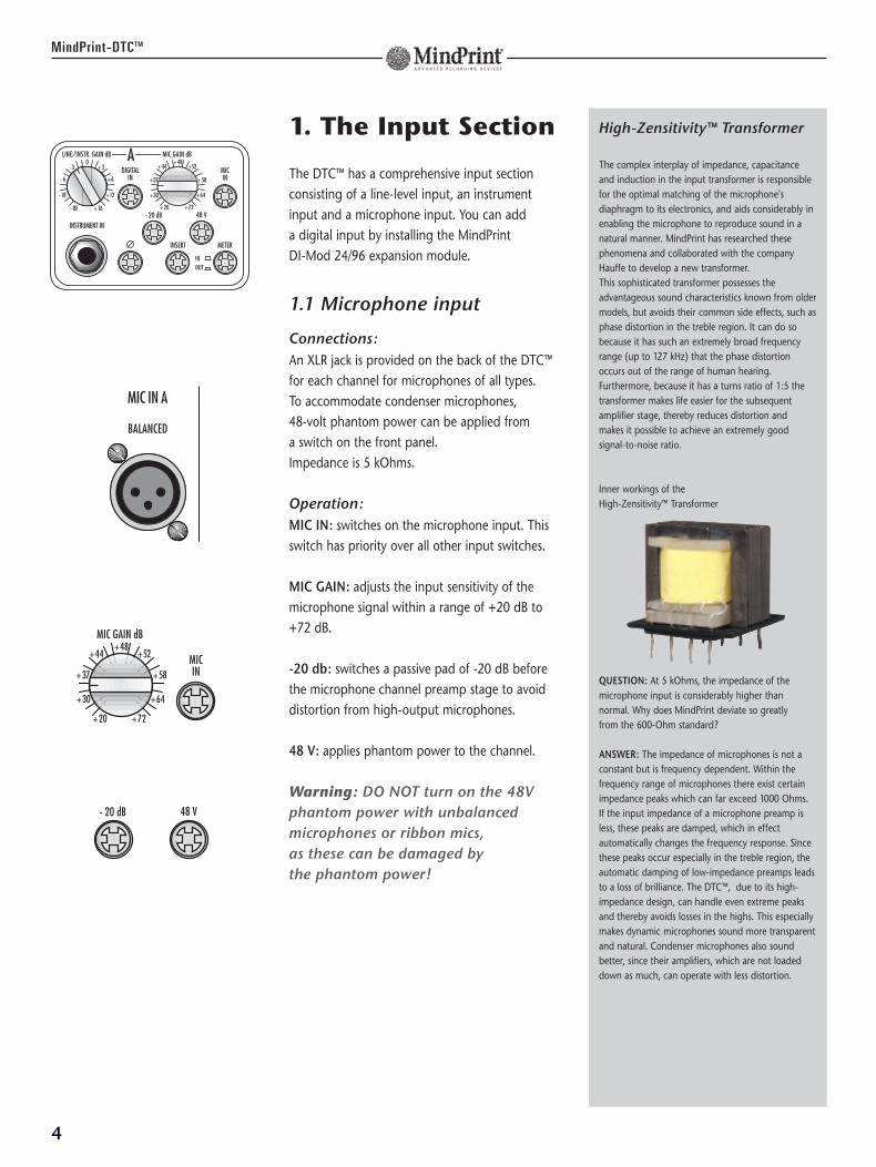
Connections:An XLR jack is provided on the back of the DTC™for each channel for microphones of all types. To accommodate condenser microphones, 48-volt phantom power can be applied from a switch on the front panel. Impedance is 5 kOhms.
Operation:MIC IN: switches on the microphone input. Thisswitch has priority over all other input switches.
MIC GAIN: adjusts the input sensitivity of themicrophone signal within a range of +20 dB to+72 dB.
-20 db: switches a passive pad of -20 dB beforethe microphone channel preamp stage to avoiddistortion from high-output microphones.
48 V: applies phantom power to the channel.
Warning: DO NOT turn on the 48Vphantom power with unbalancedmicrophones or ribbon mics, as these can be damaged by the phantom power!
4
MindPrint-DTCTM
High-Zensitivity™ Transformer
The complex interplay of impedance, capacitanceand induction in the input transformer is responsiblefor the optimal matching of the microphone'sdiaphragm to its electronics, and aids considerably inenabling the microphone to reproduce sound in anatural manner. MindPrint has researched thesephenomena and collaborated with the companyHauffe to develop a new transformer. This sophisticated transformer possesses theadvantageous sound characteristics known from oldermodels, but avoids their common side effects, such asphase distortion in the treble region. It can do sobecause it has such an extremely broad frequencyrange (up to 127 kHz) that the phase distortionoccurs out of the range of human hearing. Furthermore, because it has a turns ratio of 1:5 thetransformer makes life easier for the subsequentamplifier stage, thereby reduces distortion and makes it possible to achieve an extremely goodsignal-to-noise ratio.
Inner workings of the High-Zensitivity™ Transformer
QUESTION: At 5 kOhms, the impedance of themicrophone input is considerably higher thannormal. Why does MindPrint deviate so greatly from the 600-Ohm standard?
ANSWER: The impedance of microphones is not aconstant but is frequency dependent. Within thefrequency range of microphones there exist certainimpedance peaks which can far exceed 1000 Ohms. If the input impedance of a microphone preamp isless, these peaks are damped, which in effectautomatically changes the frequency response. Sincethese peaks occur especially in the treble region, theautomatic damping of low-impedance preamps leadsto a loss of brilliance. The DTC™, due to its high-impedance design, can handle even extreme peaksand thereby avoids losses in the highs. This especiallymakes dynamic microphones sound more transparentand natural. Condenser microphones also soundbetter, since their amplifiers, which are not loadeddown as much, can operate with less distortion.
MIC IN A
BALANCED
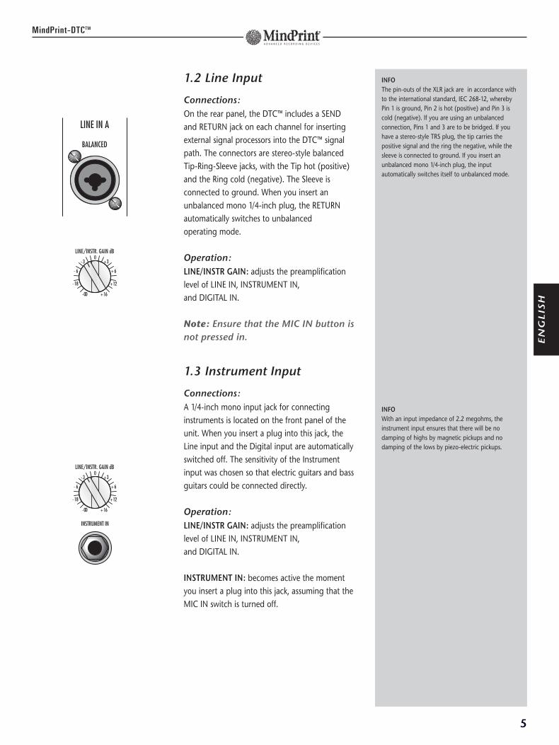
1.2 Line Input
Connections:On the rear panel, the DTC™ includes a SENDand RETURN jack on each channel for insertingexternal signal processors into the DTC™ signalpath. The connectors are stereo-style balancedTip-Ring-Sleeve jacks, with the Tip hot (positive)and the Ring cold (negative). The Sleeve isconnected to ground. When you insert anunbalanced mono 1/4-inch plug, the RETURNautomatically switches to unbalanced operating mode.
Operation:LINE/INSTR GAIN: adjusts the preamplificationlevel of LINE IN, INSTRUMENT IN, and DIGITAL IN.
Note: Ensure that the MIC IN button isnot pressed in.
1.3 Instrument Input
Connections:A 1/4-inch mono input jack for connectinginstruments is located on the front panel of theunit. When you insert a plug into this jack, theLine input and the Digital input are automaticallyswitched off. The sensitivity of the Instrumentinput was chosen so that electric guitars and bassguitars could be connected directly.
Operation:LINE/INSTR GAIN: adjusts the preamplificationlevel of LINE IN, INSTRUMENT IN, and DIGITAL IN.
INSTRUMENT IN: becomes active the momentyou insert a plug into this jack, assuming that theMIC IN switch is turned off.
5
MindPrint-DTCTM
INFOThe pin-outs of the XLR jack are in accordance withto the international standard, IEC 268-12, wherebyPin 1 is ground, Pin 2 is hot (positive) and Pin 3 iscold (negative). If you are using an unbalancedconnection, Pins 1 and 3 are to be bridged. If youhave a stereo-style TRS plug, the tip carries thepositive signal and the ring the negative, while thesleeve is connected to ground. If you insert anunbalanced mono 1/4-inch plug, the inputautomatically switches itself to unbalanced mode.
INFOWith an input impedance of 2.2 megohms, theinstrument input ensures that there will be nodamping of highs by magnetic pickups and nodamping of the lows by piezo-electric pickups.
EN
GL
ISH
LINE IN A
BALANCED
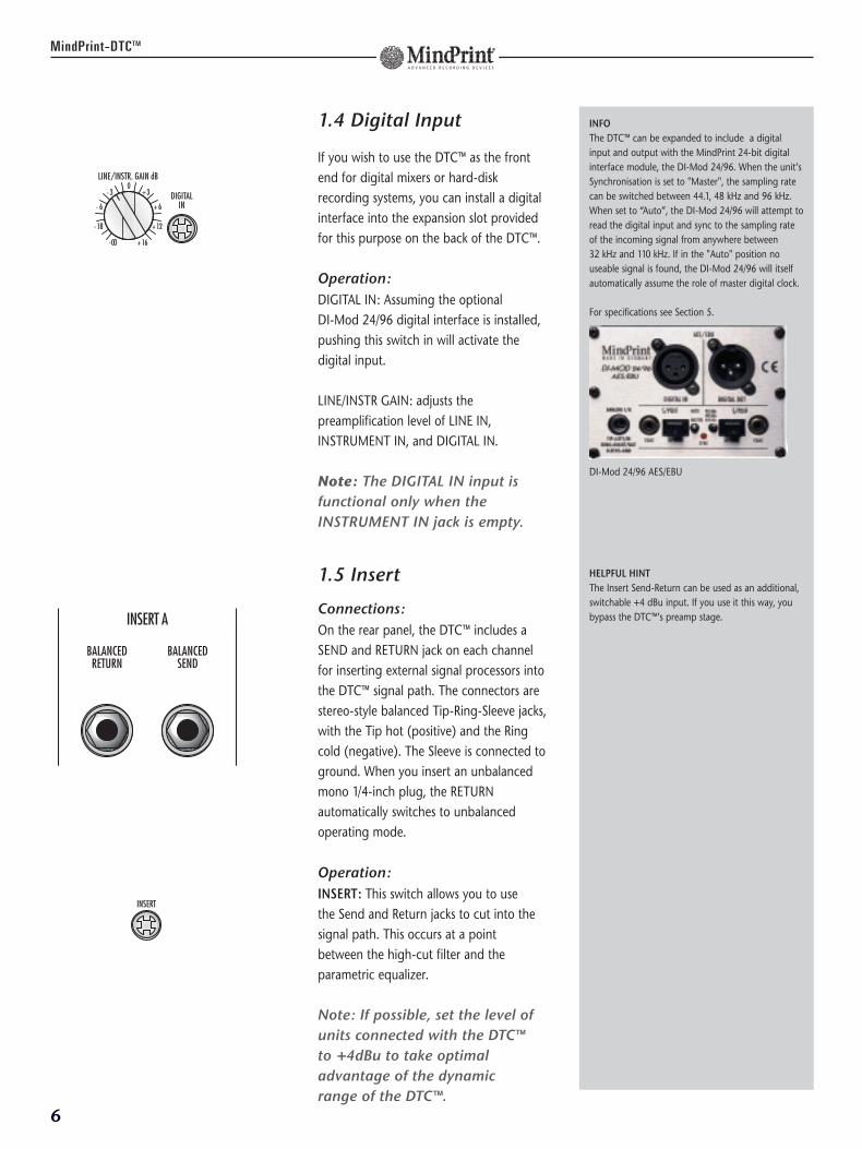
1.4 Digital Input
If you wish to use the DTC™ as the frontend for digital mixers or hard-diskrecording systems, you can install a digitalinterface into the expansion slot providedfor this purpose on the back of the DTC™.
Operation:DIGITAL IN: Assuming the optional DI-Mod 24/96 digital interface is installed,pushing this switch in will activate thedigital input.
LINE/INSTR GAIN: adjusts thepreamplification level of LINE IN,INSTRUMENT IN, and DIGITAL IN.
Note: The DIGITAL IN input isfunctional only when theINSTRUMENT IN jack is empty.
1.5 Insert
Connections:On the rear panel, the DTC™ includes aSEND and RETURN jack on each channelfor inserting external signal processors intothe DTC™ signal path. The connectors arestereo-style balanced Tip-Ring-Sleeve jacks,with the Tip hot (positive) and the Ringcold (negative). The Sleeve is connected toground. When you insert an unbalancedmono 1/4-inch plug, the RETURNautomatically switches to unbalancedoperating mode.
Operation:INSERT: This switch allows you to use the Send and Return jacks to cut into thesignal path. This occurs at a point between the high-cut filter and theparametric equalizer.
Note: If possible, set the level ofunits connected with the DTC™ to +4dBu to take optimal advantage of the dynamic range of the DTC™.
6
MindPrint-DTCTM
INFOThe DTC™ can be expanded to include a digitalinput and output with the MindPrint 24-bit digitalinterface module, the DI-Mod 24/96. When the unit’sSynchronisation is set to "Master", the sampling ratecan be switched between 44.1, 48 kHz and 96 kHz.When set to “Auto”, the DI-Mod 24/96 will attempt toread the digital input and sync to the sampling rateof the incoming signal from anywhere between 32 kHz and 110 kHz. If in the "Auto" position nouseable signal is found, the DI-Mod 24/96 will itselfautomatically assume the role of master digital clock.
For specifications see Section 5.
DI-Mod 24/96 AES/EBU
HELPFUL HINT The Insert Send-Return can be used as an additional,switchable +4 dBu input. If you use it this way, youbypass the DTC™’s preamp stage.
BALANCEDSEND
INSERT A
BALANCEDRETURN
1.6 Metering Display Switch
Operation:METER: Switches the display between Input and Output.
IN: Displays the level of the Input signal.
OUT: Displays the level of the Output signal.
Note: Take care when adjusting inputlevels that the level remains in thegreen, as this will leave enoughheadroom for later processing stages.The Output display works like thedisplay of a digital device; that is, ifthe red “OVER” LED lights up, you runserious risk of unwanted distortion.
1.7 Phase Reverse
The Phase Reverse switch reverses the phase ofthe input signal by 180 degrees.
Operation:Ø: Activates the phase reversal feature.
Warning: Using this feature as an”effect” with signals that are in fact properly in phase is notrecommended, as this may createproblems with mono compatibility.
7
MindPrint-DTCTM
INFO The values on the display are given in dB Fs tosimplify properly driving the optional DI-Modconverter or other digital devices. The display iscalibrated in such a way that the value “-10” (the last green LED) corresponds to a reference level of+4dBu. This is the value to aim for to achieve thebest levels. The equalizer and compressor respondoptimally when you use an input level in this range.
The output should be driven as high as possiblewithout going into the red in order to take fulladvantage of the dynamics available with theoptional DI-Mod (or other A/D converter). You maythink of this display as similar to that of a DAT recorder, in that you strive to push the level as high as possible without going over.
HELPFUL HINTThe Phase Reverse switch may help in correctingsignals whose polarity is reversed or in reducing thephase shifting that results when the same soundsources cross-bleed into several open microphones. In live use on stage, phase reversal can be helpful insuppressing low-frequency feedback.
EN
GL
ISH
2. Equalization: Frequency Processing
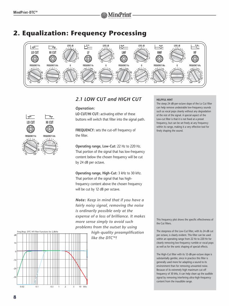
2.1 LOW CUT and HIGH CUT
Operation:LO CUT/HI CUT: activating either of thesebuttons will switch that filter into the signal path.
FREQUENCY: sets the cut-off frequency of the filter.
Operating range, Low-Cut: 22 Hz to 220 Hz.That portion of the signal that has low-frequencycontent below the chosen frequency will be cutby 24 dB per octave.
Operating range, High-Cut: 3 kHz to 30 kHz.That portion of the signal that has high-frequency content above the chosen frequencywill be cut by 12 dB per octave.
Note: Keep in mind that if you have afairly noisy signal, removing the noiseis ordinarily possible only at theexpense of a loss of brilliance. It makesmore sense simply to avoid suchproblems from the outset by using
high-quality preamplificationlike the DTC™!
8
MindPrint-DTCTM
HELPFUL HINTThe steep 24 dB-per-octave slope of the Lo Cut filtercan help remove undesirable low-frequency soundssuch as vocal pops cleanly without any degradationof the rest of the signal. A special aspect of the Low-cut filter is that it is not fixed at a presetfrequency, but can be set freely at any frequencywithin its range, making it a very effective tool forfinely shaping the sound.
This frequency plot shows the specific effectiveness ofthe Cut filters.
The steepness of the Low-Cut filter, with its 24-dB cutper octave, is clearly evident. This filter can be usedwithin an operating range from 22 Hz to 220 Hz forcleanly removing low-frequency rumble or vocal popsas well as for the sonic shaping of special effects.
The High-Cut filter with its 12-dB-per-octave slope issubstantially gentler, since in practice this filter isgenerally used more for adapting a sound to itsenvironment than for removing unwanted noise.Because of its extremely high maximum cut-offfrequency of 30 kHz, it can help clean up the audiblesignal by removing interfering ultra-high-frequencycontent from the inaudible range.
Freq.Resp. DTC HF-Filter Functions for 2,8kHz
0.02 0.1 0.5 1 2 5 10 kHz
dB
10
0
-10
-20
-30
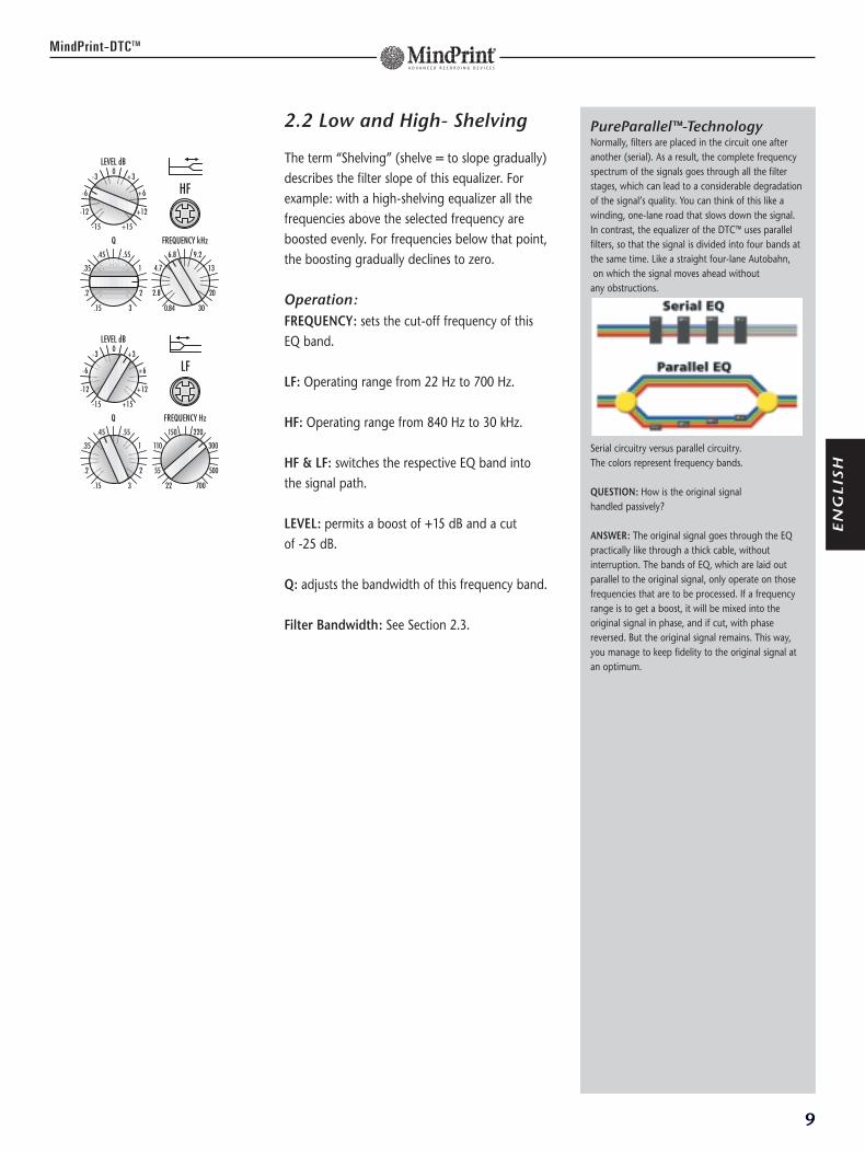
2.2 Low and High- Shelving
The term “Shelving” (shelve = to slope gradually)describes the filter slope of this equalizer. Forexample: with a high-shelving equalizer all thefrequencies above the selected frequency areboosted evenly. For frequencies below that point,the boosting gradually declines to zero.
Operation:FREQUENCY: sets the cut-off frequency of thisEQ band.
LF: Operating range from 22 Hz to 700 Hz.
HF: Operating range from 840 Hz to 30 kHz.
HF & LF: switches the respective EQ band intothe signal path.
LEVEL: permits a boost of +15 dB and a cut of -25 dB.
Q: adjusts the bandwidth of this frequency band.
Filter Bandwidth: See Section 2.3.
9
MindPrint-DTCTM
PureParallel™-TechnologyNormally, filters are placed in the circuit one afteranother (serial). As a result, the complete frequencyspectrum of the signals goes through all the filterstages, which can lead to a considerable degradationof the signal’s quality. You can think of this like awinding, one-lane road that slows down the signal. In contrast, the equalizer of the DTC™ uses parallelfilters, so that the signal is divided into four bands atthe same time. Like a straight four-lane Autobahn,on which the signal moves ahead without
any obstructions.
Serial circuitry versus parallel circuitry.The colors represent frequency bands.
QUESTION: How is the original signal handled passively?
ANSWER: The original signal goes through the EQpractically like through a thick cable, withoutinterruption. The bands of EQ, which are laid outparallel to the original signal, only operate on thosefrequencies that are to be processed. If a frequencyrange is to get a boost, it will be mixed into theoriginal signal in phase, and if cut, with phasereversed. But the original signal remains. This way,you manage to keep fidelity to the original signal atan optimum.
EN
GL
ISH
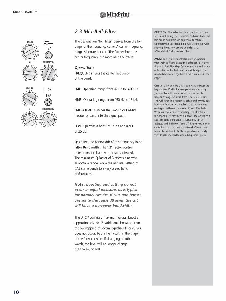
2.3 Mid-Bell-Filter
The designation “bell filter” derives from the bellshape of the frequency curve. A certain frequencyrange is boosted or cut. The farther from thecenter frequency, the more mild the effect.
Operation:FREQUENCY: Sets the center frequency of the band.
LMF: Operating range from 47 Hz to 1600 Hz
HMF: Operating range from 190 Hz to 13 kHz
LMF & HMF: switches the Lo-Mid or Hi-Midfrequency band into the signal path.
LEVEL: permits a boost of 15 dB and a cut of 25 dB.
Q: adjusts the bandwidth of this frequency band.Filter Bandwidth: The “Q“ Factor controldetermines the bandwidth that is affected. The maximum Q Factor of 3 affects a narrow, 1/3-octave range, while the minimal setting of0.15 corresponds to a very broad band of 6 octaves.
Note: Boosting and cutting do notoccur in equal measure, as is typicalfor parallel circuits. If cuts and boostsare set to the same dB level, the cutwill have a narrower bandwidth.
The DTC™ permits a maximum overall boost ofapproximately 20 dB. Additional boosting fromthe overlapping of several equalizer filter curvesdoes not occur, but rather results in the shape of the filter curve itself changing. In other words, the level will no longer change, but the sound will.
10
MindPrint-DTCTM
QUESTION: The treble band and the bass band areset up as shelving filters, whereas both mid bands arelaid out as bell filters. An adjustable Q control,common with bell-shaped filters, is uncommon withshelving filters. How are we to understand a "bandwidth" with shelving filters?
ANSWER: A Q-factor control is quite uncommonwith shelving filters, although it adds considerably tothe sonic flexibility. High Q-factor settings in the caseof boosting will at first produce a slight dip in themiddle frequency range before the curve rises at theedges.
One can think of it like this. If you want to boost thehighs above 10 kHz, for example when mastering,you can shape the curve in such a way that thefrequency range below it, from 8 to 10 kHz, is cut.This will result in a supremely soft sound. Or you canboost the low bass without having to worry aboutending up with mud between 150 and 300 Hertz.When cutting instead of boosting, the effect is justthe opposite. At first there is a boost, and only then acut. The good thing about it is that this can beadjusted with infinite variation. This gives you a lot ofcontrol, so much so that you often don't even needto use the mid controls. The applications are reallyvery flexible and lead to astonishing sonic results.
11
MindPrint-DTCTM
EN
GL
ISH
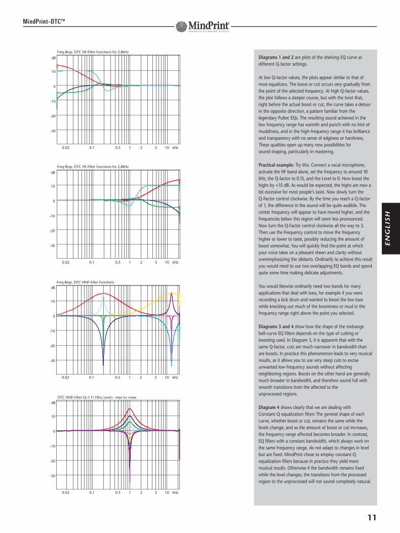
Diagrams 1 and 2 are plots of the shelving EQ curve atdifferent Q-factor settings.
At low Q-factor values, the plots appear similar to that ofmost equalizers. The boost or cut occurs very gradually fromthe point of the selected frequency. At high Q-factor values,the plot follows a steeper course, but with the twist that,right before the actual boost or cut, the curve takes a detourin the opposite direction, a pattern familiar from thelegendary Pultec EQs. The resulting sound achieved in thelow frequency range has warmth and punch with no hint ofmuddiness, and in the high-frequency range it has brillianceand transparency with no sense of edginess or harshness.These qualities open up many new possibilities for sound-shaping, particularly in mastering.
Practical example: Try this. Connect a vocal microphone,activate the HF band alone, set the frequency to around 10kHz, the Q-factor to 0.15, and the Level to 0. Now boost thehighs by +15 dB. As would be expected, the highs are now abit excessive for most people’s taste. Now slowly turn the Q-Factor control clockwise. By the time you reach a Q-factorof 1, the difference in the sound will be quite audible. Thecenter frequency will appear to have moved higher, and thefrequencies below this region will seem less pronounced.Now turn the Q-Factor control clockwise all the way to 3.Then use the Frequency control to move the frequencyhigher or lower to taste, possibly reducing the amount ofboost somewhat. You will quickly find the point at whichyour voice takes on a pleasant sheen and clarity withoutoveremphasizing the sibilants. Ordinarily to achieve this resultyou would need to use two overlapping EQ bands and spendquite some time making delicate adjustments.
You would likewise ordinarily need two bands for manyapplications that deal with bass, for example if you wererecording a kick drum and wanted to boost the low basswhile knocking out much of the boominess or mud in thefrequency range right above the point you selected.
Diagrams 3 and 4 show how the shape of the midrangebell-curve EQ filters depends on the type of cutting orboosting used. In Diagram 3, it is apparent that with thesame Q-factor, cuts are much narrower in bandwidth thanare boosts. In practice this phenomenon leads to very musicalresults, as it allows you to use very steep cuts to exciseunwanted low-frequency sounds without affectingneighboring regions. Boosts on the other hand are generallymuch broader in bandwidth, and therefore sound full withsmooth transitions from the affected to the unprocessed regions.
Diagram 4 shows clearly that we are dealing with Constant-Q equalization filters The general shape of eachcurve, whether boost or cut, remains the same while thelevels change; and as the amount of boost or cut increases,the frequency range affected becomes broader. In contrast,EQ filters with a constant bandwidth, which always work onthe same frequency range, do not adapt to changes in levelbut are fixed. MindPrint chose to employ constant-Qequalization filters because in practice they yield moremusical results. Otherwise if the bandwidth remains fixedwhile the level changes, the transitions from the processedregion to the unprocessed will not sound completely natural.
Freq.Resp. DTC HF-Filter Functions for 2,8kHz
0.02 0.1 0.5 1 2 5 10 kHz
dB
10
0
-10
-20
-30
12
MindPrint-DTCTM
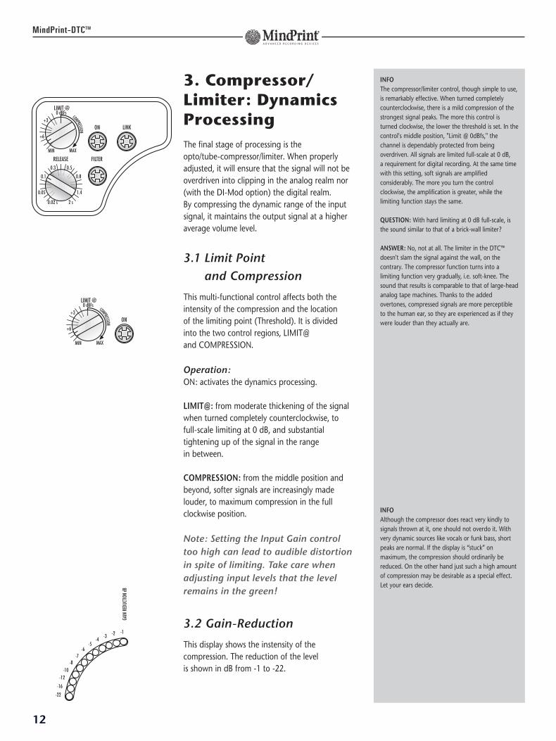
3. Compressor/Limiter: DynamicsProcessingThe final stage of processing is the opto/tube-compressor/limiter. When properlyadjusted, it will ensure that the signal will not beoverdriven into clipping in the analog realm nor(with the DI-Mod option) the digital realm. By compressing the dynamic range of the inputsignal, it maintains the output signal at a higheraverage volume level.
3.1 Limit Point and Compression
This multi-functional control affects both theintensity of the compression and the location of the limiting point (Threshold). It is dividedinto the two control regions, LIMIT@ and COMPRESSION.
Operation:ON: activates the dynamics processing.
LIMIT@: from moderate thickening of the signalwhen turned completely counterclockwise, tofull-scale limiting at 0 dB, and substantialtightening up of the signal in the range in between.
COMPRESSION: from the middle position andbeyond, softer signals are increasingly madelouder, to maximum compression in the fullclockwise position.
Note: Setting the Input Gain controltoo high can lead to audible distortionin spite of limiting. Take care whenadjusting input levels that the levelremains in the green!
3.2 Gain-Reduction
This display shows the instensity of thecompression. The reduction of the level is shown in dB from -1 to -22.
INFOThe compressor/limiter control, though simple to use,is remarkably effective. When turned completelycounterclockwise, there is a mild compression of thestrongest signal peaks. The more this control isturned clockwise, the lower the threshold is set. In thecontrol's middle position, "Limit @ 0dBfs," thechannel is dependably protected from beingoverdriven. All signals are limited full-scale at 0 dB, a requirement for digital recording. At the same timewith this setting, soft signals are amplifiedconsiderably. The more you turn the controlclockwise, the amplification is greater, while thelimiting function stays the same.
QUESTION: With hard limiting at 0 dB full-scale, isthe sound similar to that of a brick-wall limiter?
ANSWER: No, not at all. The limiter in the DTC™doesn't slam the signal against the wall, on thecontrary. The compressor function turns into alimiting function very gradually, i.e. soft-knee. Thesound that results is comparable to that of large-headanalog tape machines. Thanks to the addedovertones, compressed signals are more perceptibleto the human ear, so they are experienced as if theywere louder than they actually are.
INFOAlthough the compressor does react very kindly tosignals thrown at it, one should not overdo it. Withvery dynamic sources like vocals or funk bass, shortpeaks are normal. If the display is “stuck” onmaximum, the compression should ordinarily bereduced. On the other hand just such a high amountof compression may be desirable as a special effect.Let your ears decide.
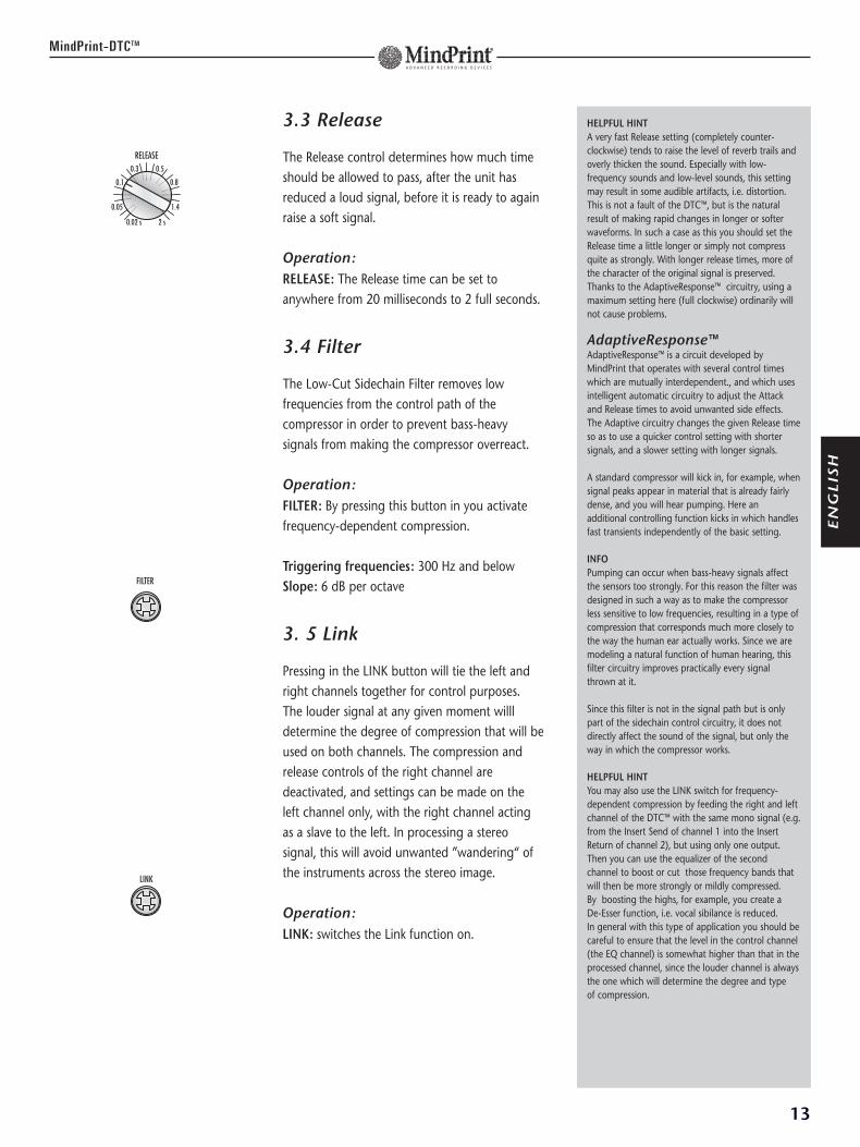
3.3 Release
The Release control determines how much timeshould be allowed to pass, after the unit hasreduced a loud signal, before it is ready to againraise a soft signal.
Operation:RELEASE: The Release time can be set toanywhere from 20 milliseconds to 2 full seconds.
3.4 Filter
The Low-Cut Sidechain Filter removes lowfrequencies from the control path of thecompressor in order to prevent bass-heavysignals from making the compressor overreact.
Operation:FILTER: By pressing this button in you activatefrequency-dependent compression.
Triggering frequencies: 300 Hz and belowSlope: 6 dB per octave
3. 5 Link
Pressing in the LINK button will tie the left andright channels together for control purposes. The louder signal at any given moment willldetermine the degree of compression that will beused on both channels. The compression andrelease controls of the right channel aredeactivated, and settings can be made on the left channel only, with the right channel actingas a slave to the left. In processing a stereosignal, this will avoid unwanted ”wandering“ ofthe instruments across the stereo image.
Operation:LINK: switches the Link function on.
13
MindPrint-DTCTM
HELPFUL HINTA very fast Release setting (completely counter-clockwise) tends to raise the level of reverb trails andoverly thicken the sound. Especially with low-frequency sounds and low-level sounds, this settingmay result in some audible artifacts, i.e. distortion.This is not a fault of the DTC™, but is the naturalresult of making rapid changes in longer or softerwaveforms. In such a case as this you should set theRelease time a little longer or simply not compressquite as strongly. With longer release times, more ofthe character of the original signal is preserved.Thanks to the AdaptiveResponse™ circuitry, using amaximum setting here (full clockwise) ordinarily willnot cause problems.
AdaptiveResponse™AdaptiveResponse™ is a circuit developed byMindPrint that operates with several control timeswhich are mutually interdependent., and which usesintelligent automatic circuitry to adjust the Attackand Release times to avoid unwanted side effects. The Adaptive circuitry changes the given Release timeso as to use a quicker control setting with shortersignals, and a slower setting with longer signals.
A standard compressor will kick in, for example, whensignal peaks appear in material that is already fairlydense, and you will hear pumping. Here anadditional controlling function kicks in which handlesfast transients independently of the basic setting.
INFOPumping can occur when bass-heavy signals affectthe sensors too strongly. For this reason the filter wasdesigned in such a way as to make the compressorless sensitive to low frequencies, resulting in a type ofcompression that corresponds much more closely tothe way the human ear actually works. Since we aremodeling a natural function of human hearing, thisfilter circuitry improves practically every signalthrown at it.
Since this filter is not in the signal path but is onlypart of the sidechain control circuitry, it does notdirectly affect the sound of the signal, but only theway in which the compressor works.
HELPFUL HINTYou may also use the LINK switch for frequency-dependent compression by feeding the right and leftchannel of the DTC™ with the same mono signal (e.g.from the Insert Send of channel 1 into the InsertReturn of channel 2), but using only one output.Then you can use the equalizer of the secondchannel to boost or cut those frequency bands thatwill then be more strongly or mildly compressed. By boosting the highs, for example, you create a De-Esser function, i.e. vocal sibilance is reduced. In general with this type of application you should becareful to ensure that the level in the control channel(the EQ channel) is somewhat higher than that in theprocessed channel, since the louder channel is alwaysthe one which will determine the degree and type of compression.
EN
GL
ISH
14
MindPrint-DTCTM
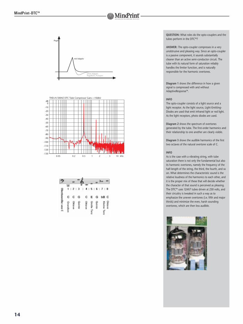
QUESTION: What roles do the opto-couplers and thetubes perform in the DTC™?
ANSWER: The opto-coupler compresses in a veryunobtrusive and pleasing way. Since an opto-coupleris a passive component, it sounds substantiallycleaner than an active semi-conductor circuit. Thetube with its natural form of saturation reliablyhandles the limiter function, and is naturallyresponsible for the harmonic overtones.
Diagram 1 shows the difference in how a givensignal is compressed with and without AdaptiveResponse™.
INFOThe opto-coupler consists of a light source and alight receptor. As the light source, Light-Emitting-Diodes are used that emit infrared light or red light.As the light receptors, photo diodes are used.
Diagram 2 shows the spectrum of overtonesgenerated by the tube. The first-order harmonics andtheir relationship to one another are clearly visible.
Diagram 3 shows the audible harmonics of the firsttwo octaves of the natural overtone scale of C.
INFOAs is the case with a vibrating string, with tubesaturation there is not only the fundamental but alsoits harmonic overtones, namely the frequency of thehalf-length of the string, the third, the fourth, and soon. What determines the characteristic sound is therelative loudness of the harmonics to each other, andit is the proper mix of these that will decide whetherthe character of that sound is perceived as pleasing.The DTC™ uses 12AX7 tubes driven at 250 volts, andtheir circuitry is tweaked in such a way as toemphasize the uneven overtones (i.e. fifth and majorthirds) and minimize the even, harsh soundingovertones, which are then less audible.
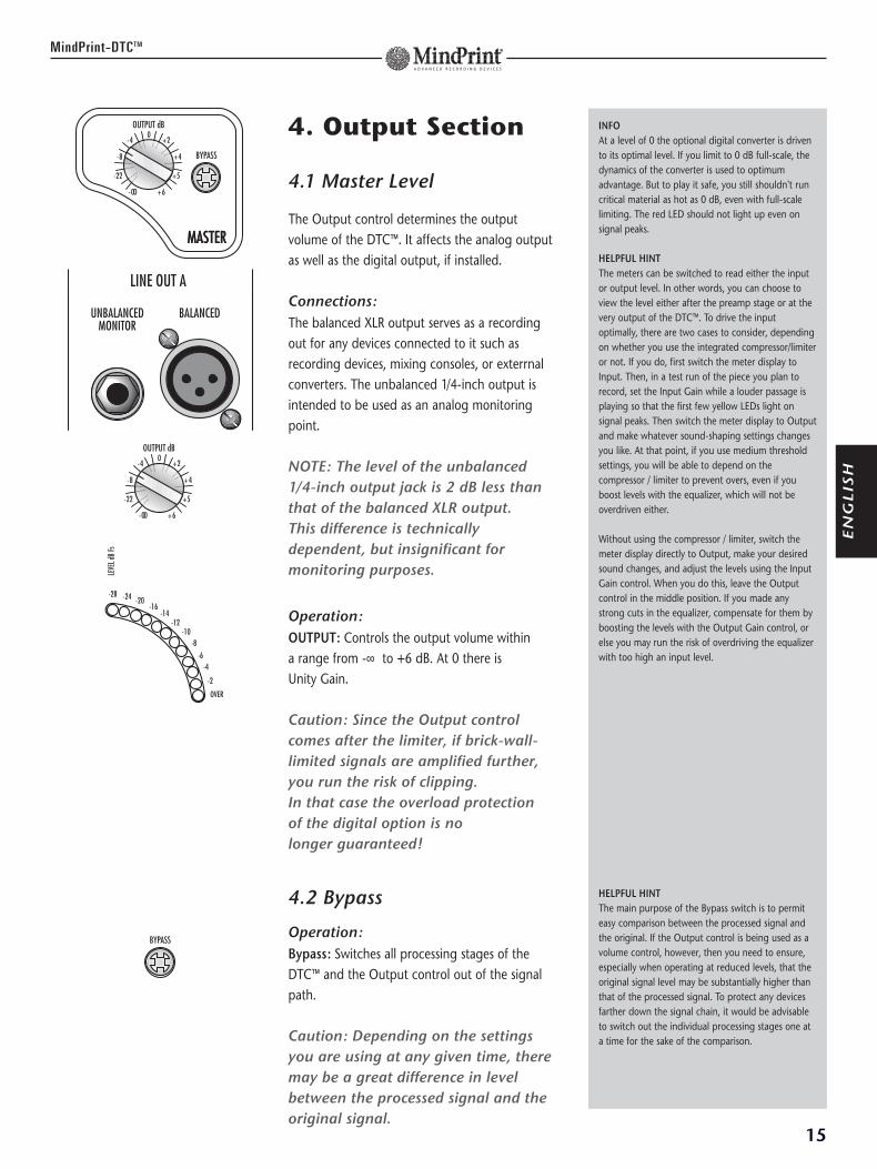
4. Output Section
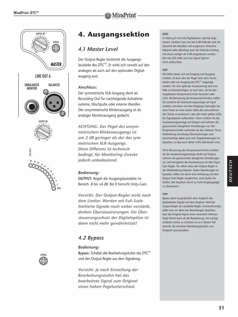
4.1 Master Level
The Output control determines the outputvolume of the DTC™. It affects the analog outputas well as the digital output, if installed.
Connections:The balanced XLR output serves as a recordingout for any devices connected to it such asrecording devices, mixing consoles, or exterrnalconverters. The unbalanced 1/4-inch output isintended to be used as an analog monitoringpoint.
NOTE: The level of the unbalanced1/4-inch output jack is 2 dB less thanthat of the balanced XLR output. This difference is technicallydependent, but insignificant formonitoring purposes.
Operation:OUTPUT: Controls the output volume within a range from -∞ to +6 dB. At 0 there is Unity Gain.
Caution: Since the Output controlcomes after the limiter, if brick-wall-limited signals are amplified further,you run the risk of clipping.In that case the overload protection of the digital option is no longer guaranteed!
4.2 Bypass
Operation:Bypass: Switches all processing stages of theDTC™ and the Output control out of the signalpath.
Caution: Depending on the settingsyou are using at any given time, theremay be a great difference in levelbetween the processed signal and theoriginal signal.
15
MindPrint-DTCTM
INFOAt a level of 0 the optional digital converter is drivento its optimal level. If you limit to 0 dB full-scale, thedynamics of the converter is used to optimumadvantage. But to play it safe, you still shouldn't runcritical material as hot as 0 dB, even with full-scalelimiting. The red LED should not light up even onsignal peaks.
HELPFUL HINTThe meters can be switched to read either the inputor output level. In other words, you can choose toview the level either after the preamp stage or at thevery output of the DTC™. To drive the inputoptimally, there are two cases to consider, dependingon whether you use the integrated compressor/limiteror not. If you do, first switch the meter display toInput. Then, in a test run of the piece you plan torecord, set the Input Gain while a louder passage isplaying so that the first few yellow LEDs light onsignal peaks. Then switch the meter display to Outputand make whatever sound-shaping settings changesyou like. At that point, if you use medium thresholdsettings, you will be able to depend on thecompressor / limiter to prevent overs, even if youboost levels with the equalizer, which will not beoverdriven either.
Without using the compressor / limiter, switch themeter display directly to Output, make your desiredsound changes, and adjust the levels using the InputGain control. When you do this, leave the Outputcontrol in the middle position. If you made anystrong cuts in the equalizer, compensate for them byboosting the levels with the Output Gain control, orelse you may run the risk of overdriving the equalizerwith too high an input level.
HELPFUL HINTThe main purpose of the Bypass switch is to permiteasy comparison between the processed signal andthe original. If the Output control is being used as avolume control, however, then you need to ensure,especially when operating at reduced levels, that theoriginal signal level may be substantially higher thanthat of the processed signal. To protect any devicesfarther down the signal chain, it would be advisableto switch out the individual processing stages one ata time for the sake of the comparison.
EN
GL
ISH
LINE OUT A
BALANCEDUNBALANCEDMONITOR
Sensitivity: 0 dBuMax. input level: +22 dBudynamic range: 117 dB
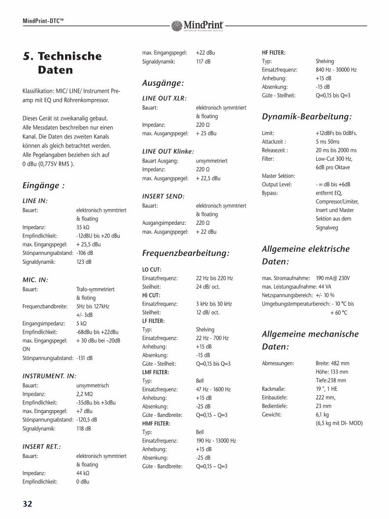
Outputs:
LINE OUT XLR: Output type: electronically
balanced & floatingOutput impedance: 220 ΩMax. output level : +25 dBu
LINE OUT 1/4“ JACK: Output type: unbalancedOutput impedance: 220 ΩMax. output level : +22.5 dBu
INSERT SEND: Output type: electronically
balanced & floatingOutput impedance: 220 ΩMax. output level : +22 dBuEQ Section:LO CUT:Corner frequency: 22 Hz - 220 HzSlope: 24 dB/oct.HI CUT:Corner frequency: 3 kHz to 30 kHzSlope: 12 dB/oct.LF FILTER:Type: ShelvingCorner frequency: 22 Hz - 700 Hz Boost: +15 dBCut: –15 dBQ=0.15 to Q=3 , adjustable from ~6dB to ~24dBLMF FILTER:Type: BellCorner frequency: 47 Hz - 1600 HzBoost: +15 dBCut: –25 dBQ=0.15 to Q=3 , adjustable from 6 octavesto 1/6 octaveHMF FILTER:Type: BellCorner frequency: 190 Hz - 13000 Hz Boost: +15 dBCut: –25 dBQ=0.15 to Q=3 , adjustable from 6 octavesto 1/6 octave
16
MindPrint-DTCTM
Technical Specifications
This device features a two-channel design.All measured data disclosed herein refers toa single channel. The second channels datais for all intents and purposes identical tothat of the first channel! All data related tolevels is referenced to 0 dBu (0.775V RMS).
Inputs :
LINE IN:Input type: electronically
balanced & floatingInput impedance: 35 kΩSensitivity: –12 dBu to +20 dBuMax. input level: +25.5 dBuSNR: –106 dB Dynamic range: 123 dB
MIC. IN:Input type: transformer
balanced & floatingFrequency bandwidth: 5 Hz to 127 kHz +/– 3 dBInput impedance: 5 kΩSensitivity: –68 dBu to + 22 dBuMax. input level: + 30 dBu
@ –20 dB ONMax. input level: + 7,5 dBu
@ –20dB OFFSNR: –131 dBDynamic range: 122 dB
INSTRUMENT IN:Input type: unbalancedInput impedance: 2,2 MΩSensitivity: –35 dBu to +3dBuMax. input level: +7 dBuInput noise voltage: –120.5 dBDynamic range: 118 dB
INSERT RETURN: Input type: electronically
balanced & floatingInput impedance: 44 kΩ
HF FILTER:Type: ShelvingCorner frequency: 840 Hz - 30000 HzBoost: +15 dBCut: –15 dBQ=0.15 to Q=3 , adjustable from von ~6dBto ~24dB
Tube Compressor Section:
TYPE: Compressor / Limiter featuring tubes, opto-coupler and Adaptive- ResponseTM.
LIMIT:Controls limiting effect from +12dBFs to0dBFs, and increase in compression fromcenter to far right positions while limitingremains constant.
Attack time : 5 ms to 50ms, depending on signal
Release time : 20 ms to 2000 ms,adjustableFilter: 300 Hz with 6dB
per octave, switchable
Signal range: 109 dB to 113 dB depending on settings
MASTER SECTION:Output level: – ∞ dB to +6dB Bypass: Removes EQ,
Compressor/Limiter, Insert and Master section from the signal path.
GENERAL MECHANICAL DATA:Dimensions: width: 482 mm
height: 133 mm depth: 238 mm
Rack dimensions: 19 “, 3 U; protrusion of controls: 23 mm
Weight: 6.1 kg
17
MindPrint-DTCTM
EN
GL
ISH
6. Appendix
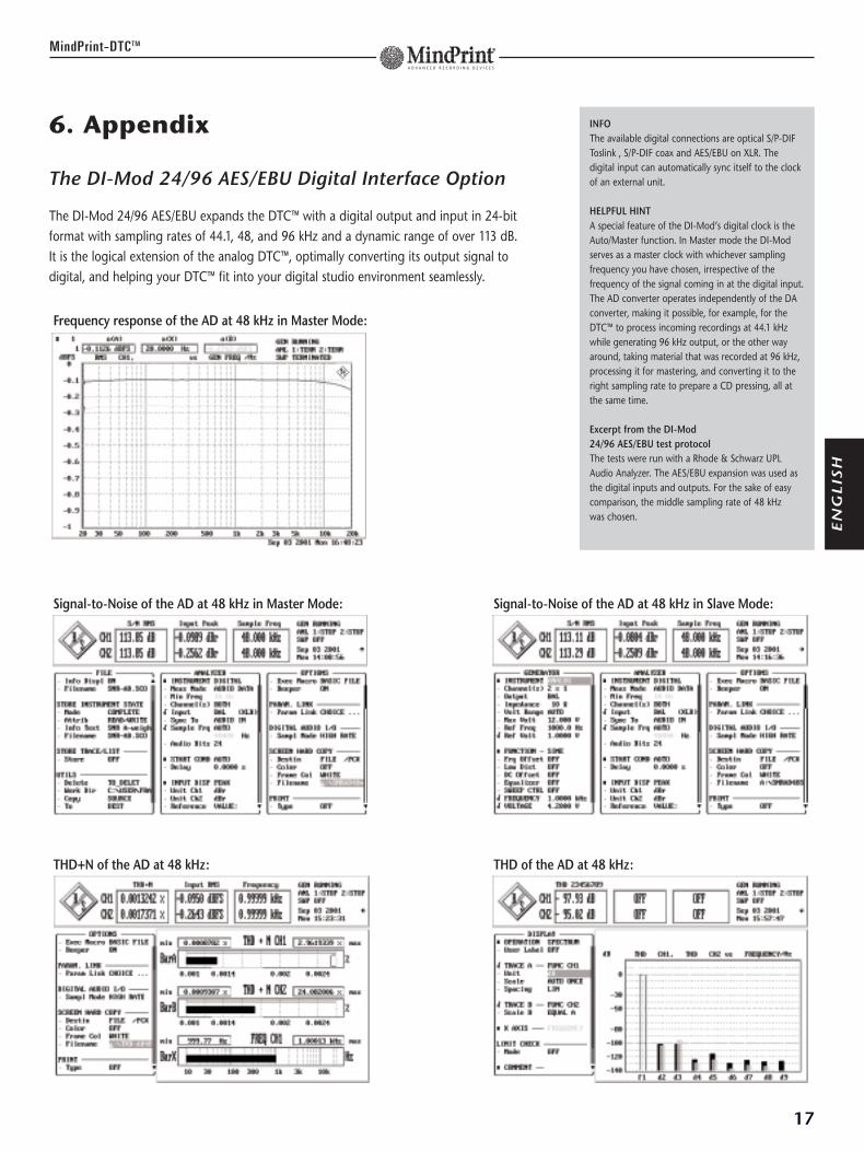
The DI-Mod 24/96 AES/EBU Digital Interface Option
The DI-Mod 24/96 AES/EBU expands the DTC™ with a digital output and input in 24-bitformat with sampling rates of 44.1, 48, and 96 kHz and a dynamic range of over 113 dB. It is the logical extension of the analog DTC™, optimally converting its output signal todigital, and helping your DTC™ fit into your digital studio environment seamlessly.
INFOThe available digital connections are optical S/P-DIFToslink , S/P-DIF coax and AES/EBU on XLR. Thedigital input can automatically sync itself to the clockof an external unit.
HELPFUL HINTA special feature of the DI-Mod’s digital clock is theAuto/Master function. In Master mode the DI-Modserves as a master clock with whichever samplingfrequency you have chosen, irrespective of thefrequency of the signal coming in at the digital input.The AD converter operates independently of the DAconverter, making it possible, for example, for theDTC™ to process incoming recordings at 44.1 kHzwhile generating 96 kHz output, or the other wayaround, taking material that was recorded at 96 kHz,processing it for mastering, and converting it to theright sampling rate to prepare a CD pressing, all atthe same time.
Excerpt from the DI-Mod 24/96 AES/EBU test protocolThe tests were run with a Rhode & Schwarz UPLAudio Analyzer. The AES/EBU expansion was used asthe digital inputs and outputs. For the sake of easycomparison, the middle sampling rate of 48 kHz was chosen.
Frequency response of the AD at 48 kHz in Master Mode:
Signal-to-Noise of the AD at 48 kHz in Master Mode: Signal-to-Noise of the AD at 48 kHz in Slave Mode:
THD+N of the AD at 48 kHz: THD of the AD at 48 kHz:

18
MindPrint-DTCTM
Herzlich Willkommen!Das Geheimnis des „teuren Sounds“ ist heute nicht mehr die Band-maschine oder das unbezahlbare Mischpult. Das wahre Geheimnis liegtin der klanglichen Substanz des Signals beim Eintritt in die digitale Welt– und genau dafür sorgt der neue MindPrint® DTC™.
Der DTCTM vereint einen hochwertigen Mikrofon-Vorverstärker, einen Equalizer und einenKompressor/Limiter in einem Gerät und stellt damit alle Funktionen eines vollständigenMischpult-Kanalzuges dar. Durch die Verbindung bewährter Analogbausteine mit der Klang-treue modernster Schaltungen verleiht er Ihren Aufnahmen Lebendigkeit und Wärme. Mitder optionalen Digitalschnittstelle fügt er sich nahtlos in Ihre digitale Studioumgebung ein.
Die Ingenieure des MindPrint®-Entwicklungsteams sind jeweils erfahrene Spezialisten aus denBereichen Röhren-, Audio-, Mischpult- und Digitaltechnologie, die ihr Know -How entspre-chend den Wünschen zahlreicher Recording-Anwender in diesem Produkt zusammen-gebracht haben.
Modernes Recording-Equipment hat während der letzten Jahre einen sehr hohen Standardbei immer populäreren Preisen erreicht. Leider wird das eigentliche Potential zumeist durchmangelnde Audioqualität bei der Bearbeitung des Eingangssignals, unzureichende Digital-wandler und wegen des Fehlens analoger Soundphänomene nicht ausgeschöpft.
Der DTCTM stellt Ihnen genau diese fehlenden Eigenschaften und Features zur Verfügung undbringt so erst die Talente Ihres Recording-Equipments zur Geltung. Der Klangeindruck wirdintensiver, plastischer und einfach musikalisch.
Das Konzept des DTCTM ist die Optimierung der Signalwege. Für jeden Anwendungsfall wirdder kürzestmögliche Signalweg gewählt, also unbenutzte Schaltungsteile komplett umgan-gen. Die Kombination von sehr effktiven, parallelen Filtern mit einem Opto-Röhrenkompres-sor und optionalen digitalen Ein- und Ausgängen mit bis zu 24Bit 96kHz macht den DTCTM
zu einem universellen Bearbeitungsgerät für alle vorkommenden Signale.
Wir wünschen Ihnen viel Spaß und Erfolg mit dem DTCTM!
St. Wendel Dezember 2001
Inhaltsverzeichnis:
1. Eingangsstufe.............................................................222. Frequenzbearbeitung ...............................................263. Dynamikbearbeitung ................................................304. Ausgang.....................................................................335. Technische Daten......................................................346. Anhang: Die Digital-Option ....................................35
19
MindPrint-DTCTM
INFOIm Digital-Zeitalter eine neue Qualität zu erreichen istkaum mehr mit einer höheren Samplingfrequenzoder Bit-Tiefe möglich. Die digitale Verarbeitungs-qualität ist besser als je zuvor und hat mit DVD einenStandard erreicht, der selbst höchsten Klang- undDynamikansprüchen genügt. Mit einer Abtastrate von96khz lassen sich Frequenzen wiedergeben, die weitmehr als doppelt so hoch liegen wie die höchsten,die wir bewußt wahrnehmen können. Eine Auflösungvon 24Bit bietet einen Dynamikumfang, der weit überdie Schmerzgrenze des menschlichen Ohres reicht.Die Übertragung aller wahrnehmbaren Details undNuancen eines Klanges wurden bisher stark durch dieTechnik begrenzt. Heute sind wir der vollständigenÜbertragung aller Bestandteile eines Klanges einengroßen Schritt näher.
FRAGE: Gerade weil die Digitaltechnik mittlerweile sohoch auflöst wäre doch die beste und kürzesteVerbindung ein reiner AD-Wandler. Warum bringtMindPrint gerade jetzt analoge High-End -Technik auf den Markt?
ANTWORT: Noch entscheidender als die Aufnahme-und Wiedergabequalität der Digital-Wandler ist dieQualität der Analogtechnik vor dem Wandler. Klangkann heute nur noch auf dem Weg von seiner analogen Entstehung bis zu seiner digitalen Auf-nahme an Qualität verlieren. Diesen Weg so gut undso kurz wie möglich zu machen ist die Aufgabe desDTCTM. Man muss eines bedenken: Der Klang vonInstrumenten und Mikrofonen entsteht analog alsStrom und Spannung und nicht als Bits und Samples.Strom und Spannung reagieren sehr empfindlich aufphysikalische Größen wie Impedanz, Kapazität undInduktion. Erst wenn diese Größen beachtet undStrom und Spannung in die "richtige Form" gebrachtworden sind kann man an eine Wandlung denken.Rein technisch gesehen ist die Aufgabe des DTCTM,einen sehr schwachen Wechselstrom mit einemweiten Frequenzspektrum zu verstärken und zu"formen". Wechselstrom hat aber seine Eigenarten: je nachdem ob Induktionen und Kapazitäten paralleloder seriell in einer Schaltung auftreten, haben dieseeine dämpfende Wirkung auf Bässe oder Höhen. Beiallen analogen Klangquellen, ob Pick-Up oder Mikro,selbst einem normalen Kabel spielen diese Größeneine Rolle und haben Einfluss auf den Sound. Diespezielle Eingangsschaltung des DTCTM respektiertdiese Größen auf eine ganz besondere Art und Weise.Das schafft die notwendige "Roh-Form" für die nach-folgende Frequenz und Dynamik-Bearbeitung.
DE
UT
SC
H
1. Eingangssektion
Der DTCTM verfügt über eine vollständige Ein-gangssektion, bestehend aus einem Line-, einemInstrumenteneingang und einem Mikrofon-eingang. Ein digitaler Eingang kann durch dieInstallation des Erweiterungsmoduls DI-MOD 24/96 nachgerüstet werden.
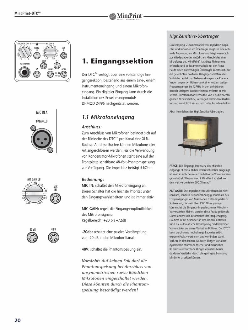
1.1 Mikrofoneingang
Anschluss:Zum Anschluss von Mikrofonen befindet sich aufder Rückseite des DTCTM pro Kanal eine XLR-Buchse. An diese Buchse können Mikrofone allerArt angeschlossen werden. Für die Verwendungvon Kondensator-Mikrofonen steht eine auf derFrontplatte schaltbare 48-Volt-Phantomspeisungzur Verfügung. Die Impedanz beträgt 5 kOhm.
Bedienung:MIC IN: schaltet den Mikrofoneingang an. Dieser Schalter hat die höchste Priorität unterden Eingangswahlschaltern und ist immer aktiv.
MIC GAIN: regelt die Eingangsempfindlichkeitdes Mikrofonsignals. Regelbereich: +20 bis +72dB
-20db: schaltet eine passive Vordämpfung von -20 dB in den Mikrofon-Kanal.
48V: schaltet die Phantomspeisung ein.
Vorsicht: Auf keinen Fall darf diePhantomspeisung bei Anschluss vonunsymmetrischen sowie Bändchen-Mikrofonen eingeschaltet werden.Diese könnten durch die Phantom-speisung beschädigt werden!
20
MindPrint-DTCTM
HighZensitive-Übertrager
Das komplexe Zusammenspiel von Impedanz, Kapa-zität und Induktion im Übertrager sorgt für eine opti-male Anpassung an Mikrofone und trägt wesentlichzur Wiedergabe des natürlichen Klangbildes einesMikrofones bei. MindPrint® hat diese Phänomeneerforscht und in Zusammenarbeit mit der FirmaHaufe einen aufwendigen Übertrager konstruiert, derdie gewohnten positiven Klangeigenschaften alterVorbilder besitzt und Nebenwirkungen wie Phasen-Verzerrungen der Höhen dank eines extrem weitenFrequenzganges bis 127kHz in den unhörbarenBereich verlagert. Darüber hinaus entlastet er mitseinem Transformationsverhältnis von 1:5 die nachfol-genden Verstärkerstufe, verringert damit den Klirrfak-tor und ermöglicht ein extrem gutes Rauschverhalten.
Abb: Innenleben des HighZensitive-Übertragers
FRAGE: Die Eingangs-Impedanz des Mikrofon-eingangs ist mit 5 KOhm wesentlich höher ausgelegtals man es üblicherweise von Mikrofon-Vorverstärkerngewohnt ist. Warum weicht MindPrint so stark vonden weit verbreiteten 600 Ohm ab?
ANTWORT: Die Impedanz von Mikrofonen ist nichtkonstant, sondern frequenzabhängig. Innerhalb desFrequenzganges von Mikrofonen treten Impedanz-Spitzen auf, die weit über 1000 Ohm springenkönnen. Ist die Eingangs-Impedanz eines Mikrofon-Vorverstärkers kleiner, werden diese Peaks gedämpft.Damit ändert sich automatisch der Frequenzgang. Da diese Peaks besonders in den Höhen auftreten,führt die automatische Bedämpfung niederohmigerVorverstärker zu einem Verlust an Brillianz. Der DTCTM
kann durch seine hochohmige Bauweise selbstextreme Peaks verarbeiten und verhindert damitVerluste in den Höhen. Dadurch klingen vor allemdynamische Mikrofone frischer und natürlicher.Kondensatormikrofone klingen ebenfalls besser, da deren Verstärker durch die geringere Belastungklirrärmer arbeiten können.
MIC IN A
BALANCED
21
DE
UT
SC
H
MindPrint-DTCTM
1.2 Line-Eingang
Anschluss:Zum Anschluss von Synthesizern, Mischpultenoder anderen Signalquellen mit Line-Pegelbefindet sich auf der Rückseite pro Kanal eineKlinke/XLR-Kombibuchse. Der Line-Eingang istautomatisch aktiv sobald der Instrumenten-Eingang nicht belegt ist und Mic-In und Digital-In ausgeschaltet sind. Er ist für symmetrische und unsymmetrische Studiopegelmit +4dBu ausgelegt. Eine spezielle Schaltungstellt bei unsymmetrischem Anschluss sicher, dass der Pegel erhalten bleibt.
Bedienung:LINE/INSTR GAIN: regelt die Vorverstärkung vonLINE-, INSTRUMENT- und DIGITAL-IN.
Achtung: LINE ist nur aktiv, wenn dieINSTRUMENT Buchse nicht belegt ist.
1.3 Instrumenten-Eingang
Anschluss:Zum Anschluss von Instrumenten befindet sichauf der Frontplatte pro Kanal eine Klinkenbuchse.Bei Belegung dieser Buchse wird der Line-Eingangund Digital-Eingang automatisch ausgeschaltet.Die Empfindlichkeit des Instrumenteneingangswurde so dimensioniert, dass Gitarren und Bässedirekt angeschlossen werden können.
Bedienung:LINE/INSTR GAIN: regelt die Vorverstärkung vonLINE-, INSTRUMENT- und DIGITAL-IN.
INSTRUMENT IN: schaltet den Instrumenten-eingang automatisch ein sobald die Buchsebelegt wird.
Achtung: Der Instrumenten-eingang ist nur aktiv wenn MIC INausgeschaltet ist!
INFODie Belegung der XLR-Buchse entspricht der interna-tionalen Norm IEC 268-12. Entsprechend dieser Normführt Pin 1 die Masse, Pin 2 das positive Signal undPin 3 das negative. Bei unsymmetrischer Beschaltungsind Pin 1 und 3 zu verbinden. Bei der Stereo-Klinkenbuchse führt die Spitze das positive und derRing das negative Signal. Der Schaft ist mit der Masseverbunden. Beim Einstecken eines unsymmetrischenMono-Klinkensteckers schaltet sich der Eingangautomatisch auf die unsymmetrische Betriebsart um.
INFOMit seiner Impedanz von 2,2 Mega-Ohm stellt derInstrumenten-Eingang sicher, dass keine Höhen-dämpfung bei magnetischen Pickups und keine Bass-dämpfung bei piezoelektrischen Abnehmern auftritt.
LINE IN A
BALANCED
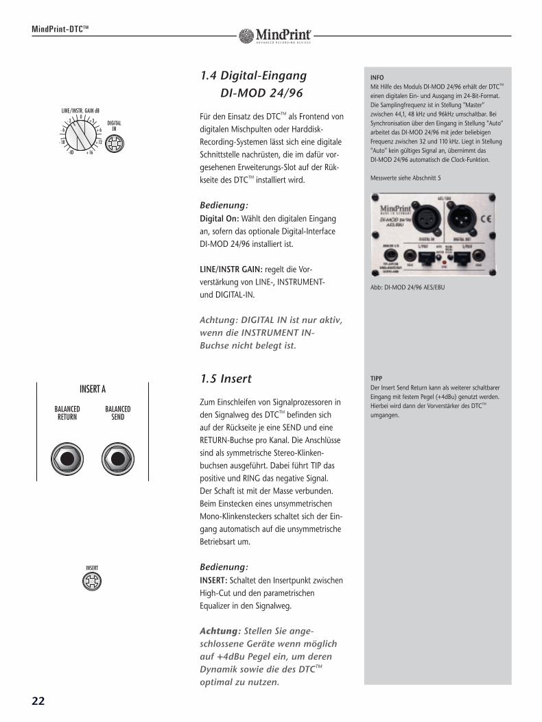
1.4 Digital-Eingang DI-MOD 24/96
Für den Einsatz des DTCTM als Frontend vondigitalen Mischpulten oder Harddisk-Recording-Systemen lässt sich eine digitaleSchnittstelle nachrüsten, die im dafür vor-gesehenen Erweiterungs-Slot auf der Rük-kseite des DTCTM installiert wird.
Bedienung:Digital On: Wählt den digitalen Eingangan, sofern das optionale Digital-InterfaceDI-MOD 24/96 installiert ist.
LINE/INSTR GAIN: regelt die Vor-verstärkung von LINE-, INSTRUMENT- und DIGITAL-IN.
Achtung: DIGITAL IN ist nur aktiv,wenn die INSTRUMENT IN-Buchse nicht belegt ist.
1.5 Insert
Zum Einschleifen von Signalprozessoren inden Signalweg des DTCTM befinden sichauf der Rückseite je eine SEND und eineRETURN-Buchse pro Kanal. Die Anschlüssesind als symmetrische Stereo-Klinken-buchsen ausgeführt. Dabei führt TIP daspositive und RING das negative Signal. Der Schaft ist mit der Masse verbunden.Beim Einstecken eines unsymmetrischenMono-Klinkensteckers schaltet sich der Ein-gang automatisch auf die unsymmetrischeBetriebsart um.
Bedienung:INSERT: Schaltet den Insertpunkt zwischenHigh-Cut und den parametrischenEqualizer in den Signalweg.
Achtung: Stellen Sie ange-schlossene Geräte wenn möglichauf +4dBu Pegel ein, um derenDynamik sowie die des DTCTM
optimal zu nutzen.
22
MindPrint-DTCTM
INFOMit Hilfe des Moduls DI-MOD 24/96 erhält der DTCTM
einen digitalen Ein- und Ausgang im 24-Bit-Format.Die Samplingfrequenz ist in Stellung "Master"zwischen 44,1, 48 kHz und 96kHz umschaltbar. BeiSynchronisation über den Eingang in Stellung "Auto"arbeitet das DI-MOD 24/96 mit jeder beliebigenFrequenz zwischen 32 und 110 kHz. Liegt in Stellung"Auto" kein gültiges Signal an, übernimmt das DI-MOD 24/96 automatisch die Clock-Funktion.
Messwerte siehe Abschnitt 5
Abb: DI-MOD 24/96 AES/EBU
TIPPDer Insert Send Return kann als weiterer schaltbarerEingang mit festem Pegel (+4dBu) genutzt werden.Hierbei wird dann der Vorverstärker des DTCTM
umgangen.BALANCED
SEND
INSERT A
BALANCEDRETURN
23
DE
UT
SC
H
MindPrint-DTCTM
1.6 Anzeigenumschaltung
Bedienung:METER: Schaltet die Anzeige zwischen Eingangund Ausgang um.
IN: Zeigt den Pegel des Eingangssignals an.
OUT: Zeigt den Pegel des Ausgangssignals an.
Achtung: Bei der Aussteuerung desEingangs sollte der Pegel im grünenBereich bleiben, um genügendHeadroom für die nachfolgendenBearbeitungs-Stufen zu haben. Die Ausgangsanzeige arbeitet wie dieAnzeige eines Digital-Gerätes: wenndie rote "OVER"-LED der Anzeigeaufleuchtet, drohen Übersteuerungen.
1.7 Phasenumkehr
Der Phase Reverse-Schalter dreht die Phasenlagedes Eingangssignals um 180 Grad.
Bedienung:Ø: Schaltet die Phasenumkehr ein.
Achtung: Eine Verwendung als"Klangeffekt" bei phasenrichtigenStereosignalen empfiehlt sich nicht, da hierdurch Probleme mit der Mono-Kompatibilität entstehen können!
INFODie Werte auf der Anzeige sind in dB Fs angegebenum Di-Mod und andere Digitalgeräte optimalaussteuern zu können. Die Anzeige ist so geeicht, dass der Wert "-10" (die letzte grüne LED) denReferenzpegel von +4dBu anzeigt. Dieser Wert gilt als Anhaltspunkt für die Eingangs-aussteuerung. Equalizer und Compressor arbeiten bei diesem Eingangspegel optimal.
Der Ausgang sollte so hoch wie möglich ausgesteuertwerden um die Dynamik des optionalen Di-Mod odernachgeschalteter Wandler voll ausnutzen zu können.Man kann in diesem Fall die Anzeige mit der einesDAT-Recorders vergleichen: so hoch wie möglich,aber niemals "over".
TIPPMit dem Phase Reverse-Schalter können falschgepolte Signale korrigiert werden oder die imZusammenspiel mehrerer Mikrofone möglichenFrequenzauslöschungen verringert werden. Bei Verwendung im Live- / Bühnenbetrieb kann eine Phasenumkehr das Feedbackverhalten im tieffrequenten Bereich verbessern.
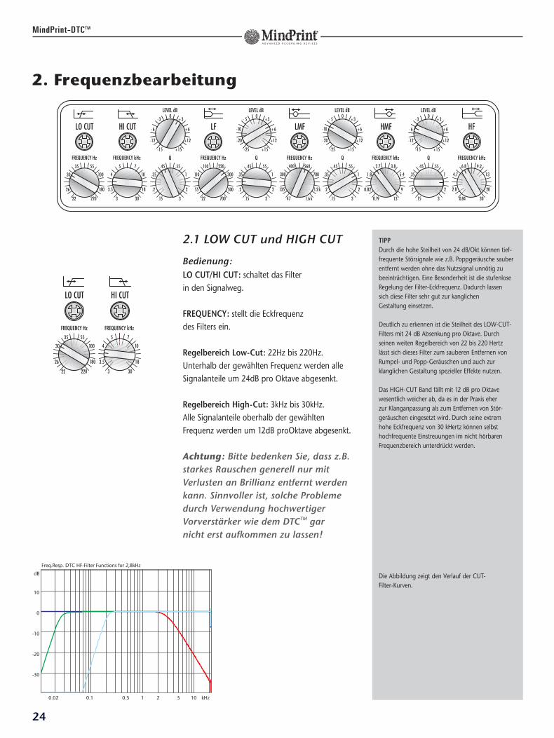
2. Frequenzbearbeitung
2.1 LOW CUT und HIGH CUT
Bedienung:LO CUT/HI CUT: schaltet das Filter in den Signalweg.
FREQUENCY: stellt die Eckfrequenz des Filters ein.
Regelbereich Low-Cut: 22Hz bis 220Hz.Unterhalb der gewählten Frequenz werden alleSignalanteile um 24dB pro Oktave abgesenkt.
Regelbereich High-Cut: 3kHz bis 30kHz.Alle Signalanteile oberhalb der gewähltenFrequenz werden um 12dB proOktave abgesenkt.
Achtung: Bitte bedenken Sie, dass z.B.starkes Rauschen generell nur mitVerlusten an Brillianz entfernt werdenkann. Sinnvoller ist, solche Problemedurch Verwendung hochwertigerVorverstärker wie dem DTCTM gar nicht erst aufkommen zu lassen!
24
MindPrint-DTCTM
TIPPDurch die hohe Steilheit von 24 dB/Okt können tief-frequente Störsignale wie z.B. Poppgeräusche sauberentfernt werden ohne das Nutzsignal unnötig zubeeinträchtigen. Eine Besonderheit ist die stufenloseRegelung der Filter-Eckfrequenz. Dadurch lassen sich diese Filter sehr gut zur kanglichen Gestaltung einsetzen.
Deutlich zu erkennen ist die Steilheit des LOW-CUT-Filters mit 24 dB Absenkung pro Oktave. Durchseinen weiten Regelbereich von 22 bis 220 Hertz lässt sich dieses Filter zum sauberen Entfernen vonRumpel- und Popp-Geräuschen und auch zurklanglichen Gestaltung spezieller Effekte nutzen.
Das HIGH-CUT Band fällt mit 12 dB pro Oktavewesentlich weicher ab, da es in der Praxis eher zur Klanganpassung als zum Entfernen von Stör-geräuschen eingesetzt wird. Durch seine extrem hohe Eckfrequenz von 30 kHertz können selbsthochfrequente Einstreuungen im nicht hörbarenFrequenzbereich unterdrückt werden.
Die Abbildung zeigt den Verlauf der CUT-Filter-Kurven.
Freq.Resp. DTC HF-Filter Functions for 2,8kHz
0.02 0.1 0.5 1 2 5 10 kHz
dB
10
0
-10
-20
-30
25
DE
UT
SC
H
MindPrint-DTCTM
2.2 LOW- und HIGH-Shelving
Der Name Shelving-Filter (shelv = sanft abfal-lend) beschreibt den Verlauf des Filters. Beispiel: Bei einem High-Shelv-Filter werden alleFrequenzbereiche oberhalb der eingestelltenEckfrequenz gleichmäßig angehoben. Für darunterliegende Frequenzen geht dieAnhebung sanft gegen Null.
Bedienung:FREQUENCY: stellt die Eckfrequenz des Bandes ein.
LF: Regelbereich von 22Hz bis 700Hz.
HF: Regelbereich von 840 kHz bis 30kHz.
HF & LF: schaltet das Band in den Signalweg.
LEVEL: erlaubt eine Anhebung von 15dB undeine Absenkung von 25dB.
Q: stellt die Güte des Bandes ein.
Filter-Güte: siehe 2.3
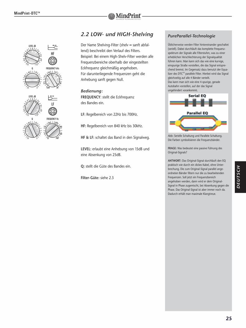
PureParallel-Technologie
Üblicherweise werden Filter hintereinander geschaltet(seriell). Dabei durchläuft das komplette Frequenz-spektrum der Signale alle Filterstufen, was zu einererheblichen Verschlechterung der Signalqualitätführen kann. Man kann sich das wie eine kurvige,einspurige Straße vorstellen, die das Signal entspre-chend bremst. Im Gegensatz dazu benutzt der Equa-lizer des DTCTM parallele Filter. Hierbei wird das Signalgleichzeitig auf alle 4 Bänder verteilt. Das kann man sich wie eine 4-spurige, geradeAutobahn vorstellen, auf der das Signal ungehindert vorankommt.
Abb: Serielle Schaltung und Parallele Schaltung.Die Farben symbolisieren die Frequenzbänder.
FRAGE: Was bedeutet eine passive Führung desOriginal-Signals?
ANTWORT: Das Original-Signal durchläuft den EQpraktisch wie durch ein dickes Kabel, ohne Unter-brechung. Die zum Original-Signal parallel ange-ordneten Bänder filtern nur die zu bearbeitendenFrequenzen. Soll jetzt ein Frequenzbereich angehoben werden, dann wird er dem Original-Signal in Phase zugemischt, bei Absenkung gegen diePhase. Das Original-Signal ist aber immer noch da. Dadurch erhält man maximale Klangtreue.
2.1 Mid-Bell-Filter
Auch die Bezeichnung Bell-Filter (engl. Bell = Glocke) leitet sich von der Form derFrequenzkurve ab. Ein bestimmter Frequenz-bereich wird angehoben oder abgesenkt. Je weiter man sich von der eingestellten Frequenzentfernt, desto geringer wird die Beeinflussung.
Bedienung:FREQUENCY: stellt die Centerfrequenz des Bandes ein.
LF: Regelbereich von 47Hz bis 1600Hz.
HF: Regelbereich von 190Hz bis 13kHz.
LMF & HMF: schaltet das Band in den Signalweg.
LEVEL: erlaubt eine Anhebung von 15dB undeine Absenkung von 25dB.
Q: stellt die Güte des Bandes ein.
Filter-Güte: Der Q-Faktor legt die Filtergüte, dasheisst die Bandbreite der Bearbeitung fest. Dermaximale Q-Faktor von 3 bewirkt eine schmal-bandige Bearbeitung im Bereich von 1/3 Oktave,der kleinste einstellbare Wert von 0,15 entsprichteinem sehr breitbandigen Umfang von 6 Oktaven.
Achtung: Anhebung und Absenkungverhalten sich nicht symmetrisch. Dies ist eine Eigenschaft parallelerSchaltungen. Bei gleicher Einstellungsind Absenkungen schmalbandiger.
Der DTCTM erlaubt eine maximale Gesamt-anhebung von ca. 20 dB. Eine weitere Additionmehrerer überlappender Filter findet nicht statt.Werte, die darüber hinaus gehen, führen zu einer Veränderung der Filterkurvenform. Es ändert sich also nicht mehr der Pegel, sondern der Klang.
26
MindPrint-DTCTM
FRAGE: Das Höhen und das Bass-Band sind alsShelving-Filter ausgelegt, die beiden Mittenbänder alsGlocken-Filter. Eine regelbare Güte wie man sie beiGlockenfiltern findet ist bei Shelving-Filtern unüblich.Wie kann man sich eine "Bandbreite" bei Shelving-Filtern vorstellen?
ANTWORT: Eine Q-Faktor-Regelung von Shelving-Filtern ist relativ selten zu finden obwohl es dieklangliche Flexibilität ungemein erhöht. Hohe Q-Faktoreinstellungen erzeugen nämlich dann beiAnhebungen zunächst eine kleine Absenkung immittleren Frequenzbereich bevor die Kurve zu denRandbereichen hin ansteigt.
Man kann sich das so vorstellen: Will man z.B. dieHöhen über 10 kHz anheben, etwa beim Mastering,kann man die Kurve so gestalten, dass der Frequenz-bereich davor von 8 bis 10 kHz abgesenkt wird. Daraus resultiert ein unübertroffen weicher Klang.Man kann auch den Tiefbass anheben, ohne denmulmigen Klang zwischen 150 und 300 Hertz zubefürchten. Bei Absenkungen kehrt sich dieser Effektum: zuerst Erfolgt eine Anhebung, dann erst eineAbsenkung. Das Gute daran ist, dass dieseCharakteristik stufenlos einstellbar ist. Man gewinnterhebliche Gestaltungsmöglichkeiten hinzu undkommt oft sogar ohne die Benutzung der Mitten-regler aus. Die Anwendungen sind wirklich sehrflexibel und führen zu erstaunlichen Klangresultaten.
27
DE
UT
SC
H
MindPrint-DTCTM
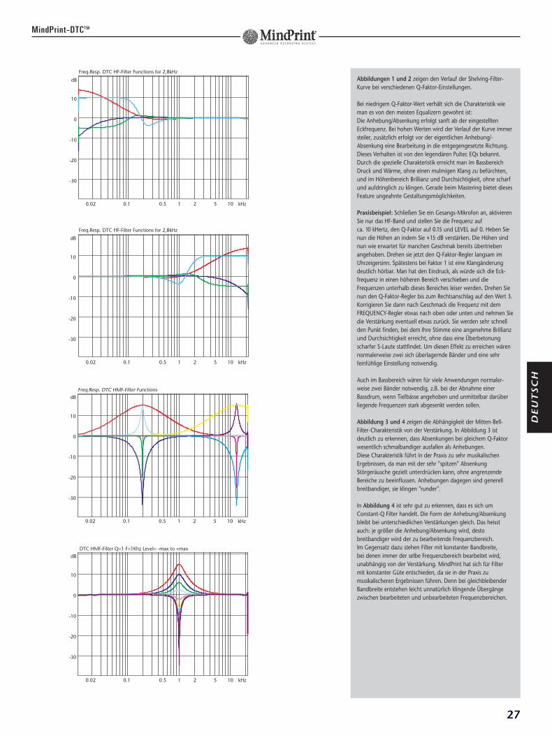
Abbildungen 1 und 2 zeigen den Verlauf der Shelving-Filter-Kurve bei verschiedenen Q-Faktor-Einstellungen.
Bei niedrigem Q-Faktor-Wert verhält sich die Charakteristik wieman es von den meisten Equalizern gewohnt ist: Die Anhebung/Absenkung erfolgt sanft ab der eingestelltenEckfrequenz. Bei hohen Werten wird der Verlauf der Kurve immersteiler, zusätzlich erfolgt vor der eigentlichen Anhebung/-Absenkung eine Bearbeitung in die entgegengesetzte Richtung.Dieses Verhalten ist von den legendären Pultec EQs bekannt.Durch die spezielle Charakteristik erreicht man im BassbereichDruck und Wärme, ohne einen mulmigen Klang zu befürchten,und im Höhenbereich Brillianz und Durchsichtigkeit, ohne scharfund aufdringlich zu klingen. Gerade beim Mastering bietet diesesFeature ungeahnte Gestaltungsmöglichkeiten.
Praxisbeispiel: Schließen Sie ein Gesangs-Mikrofon an, aktivierenSie nur das HF-Band und stellen Sie die Frequenz auf ca. 10 kHertz, den Q-Faktor auf 0.15 und LEVEL auf 0. Heben Sienun die Höhen an indem Sie +15 dB verstärken. Die Höhen sindnun wie erwartet für manchen Geschmak bereits übertriebenangehoben. Drehen sie jetzt den Q-Faktor-Regler langsam imUhrzeigersinn. Spätestens bei Faktor 1 ist eine Klangänderungdeutlich hörbar. Man hat den Eindruck, als würde sich die Eck-frequenz in einen höheren Bereich verschieben und dieFrequenzen unterhalb dieses Bereiches leiser werden. Drehen Sienun den Q-Faktor-Regler bis zum Rechtsanschlag auf den Wert 3.Korrigieren Sie dann nach Geschmack die Frequenz mit demFREQUENCY-Regler etwas nach oben oder unten und nehmen Siedie Verstärkung eventuell etwas zurück. Sie werden sehr schnellden Punkt finden, bei dem Ihre Stimme eine angenehme Brillianzund Durchsichtigkeit erreicht, ohne dass eine Überbetonungscharfer S-Laute stattfindet. Um diesen Effekt zu erreichen wärennormalerweise zwei sich überlagernde Bänder und eine sehrfeinfühlige Einstellung notwendig.
Auch im Bassbereich wären für viele Anwendungen normaler-weise zwei Bänder notwendig, z.B. bei der Abnahme einerBassdrum, wenn Tiefbässe angehoben und unmittelbar darüberliegende Frequenzen stark abgesenkt werden sollen.
Abbildung 3 und 4 zeigen die Abhängigkeit der Mitten-Bell-Filter-Charakteristik von der Verstärkung. In Abbildung 3 istdeutlich zu erkennen, dass Absenkungen bei gleichem Q-Faktorwesentlich schmalbandiger ausfallen als Anhebungen. Diese Charakteristik führt in der Praxis zu sehr musikalischenErgebnissen, da man mit der sehr "spitzen" Absenkung Störgeräusche gezielt unterdrücken kann, ohne angrenzende Bereiche zu beeinflussen. Anhebungen dagegen sind generellbreitbandiger, sie klingen "runder".
In Abbildung 4 ist sehr gut zu erkennen, dass es sich umConstant-Q Filter handelt. Die Form der Anhebung/Absenkungbleibt bei unterschiedlichen Verstärkungen gleich. Das heisstauch: je größer die Anhebung/Absenkung wird, desto breitbandiger wird der zu bearbeitende Frequenzbereich. Im Gegensatz dazu stehen Filter mit konstanter Bandbreite, bei denen immer der selbe Frequenzbereich bearbeitet wird, unabhängig von der Verstärkung. MindPrint hat sich für Filter mit konstanter Güte entschieden, da sie in der Praxis zumusikalischeren Ergebnissen führen. Denn bei gleichbleibenderBandbreite entstehen leicht unnatürlich klingende Übergängezwischen bearbeiteten und unbearbeiteten Frequenzbereichen.
Freq.Resp. DTC HF-Filter Functions for 2,8kHz
0.02 0.1 0.5 1 2 5 10 kHz
dB
10
0
-10
-20
-30
28
MindPrint-DTCTM
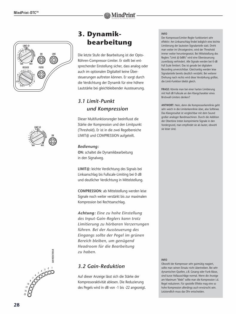
3. Dynamik-bearbeitung
Die letzte Stufe der Bearbeitung ist der Opto-Röhren-Compressor-Limiter. Er stellt bei ent-sprechender Einstellung sicher, dass analog oderauch im optionalen Digitalteil keine Über-steuerungen auftreten können. Er sorgt durchdie Verdichtung der Dynamik für eine höhereLautstärke bei gleichbleibender Aussteuerung.
3.1 Limit-Punkt und Kompression
Dieser Multifunktionsregler beeinflusst die Stärke der Kompression und den Limitpunkt(Threshold). Er ist in die zwei RegelbereicheLIMIT@ und COMPRESSION aufgeteilt.
Bedienung:ON: schaltet die Dynamikbearbeitung in den Signalweg.
LIMIT@: leichte Verdichtung des Signals beiLinksanschlag bis Fullscale-Limiting bei 0 dB und deutlicher Verdichtung in Mittelstellung.
COMPRESSION: ab Mittelstellung werden leiseSignale noch weiter verstärkt bis zur maximalenKompression bei Rechtsanschlag.
Achtung: Eine zu hohe Einstellung des Input-Gain-Reglers kann trotzLimitierung zu hörbaren Verzerrungenführen. Bei der Aussteuerung desEingangs sollte der Pegel im grünenBereich bleiben, um genügend Headroom für die Bearbeitung zu haben.
3.2 Gain-Reduktion
Auf dieser Anzeige lässt sich die Stärke derKompressoraktivität ablesen. Die Reduzierung des Pegels wird in dB von -1 bis -22 angezeigt.
INFODer Kompressor/Limiter-Regler funktioniert sehreffektiv: Am Linksanschlag findet lediglich eine leichteLimitierung der lautesten Signalanteile statt. Drehtman weiter im Uhrzeigersinn, wird der Thresholdimmer weiter heruntergesetzt. Bei Mittelstellung desReglers "Limit @ 0dBfs" wird eine Übersteuerungzuverlässig verhindert. Alle Signale werden bei 0 dBFull Scale limitiert. Das ist gerade bei digitalemRecording unverzichtbar. Gleichzeitig werden leiseSignalanteile bereits deutlich verstärkt. Bei weitererDrehung nach rechts wird diese Verstärkung größer,die Limit-Funktion bleibt gleich.
FRAGE: Könnte man bei einer harten Limitierung mit Null dB Fullscale an den Klangcharakter einesBrickwall-Limiters denken?
ANTWORT: Nein, denn die Kompressorkennlinie gehtsehr weich in die Limiterkennlinie über, also Softknee.Das Klangresultat ist vergleichbar mit dem Soundgroßer analoger Bandmaschinen. Durch die Additionder Obertöne treten komprimierte Signale in denVordergrund, man empfindet sie als lauter, obwohlsie leiser sind.
INFOObwohl der Kompressor sehr gutmütig reagiert,sollte man seinen Einsatz nicht übertreiben. Bei sehrdynamischen Quellen, z.B. Gesang oder Funk-Bässe,sind kurze Vollausschläge normal. Wenn die Anzeigeam Maximum "klebt" sollte man die Kompression i.d.Regel reduzieren. Für spezielle Effekte mag eine sohohe Kompression allerdings auch erwünscht sein.Letztendlich muss das Ohr entscheiden.
29
DE
UT
SC
H
MindPrint-DTCTM
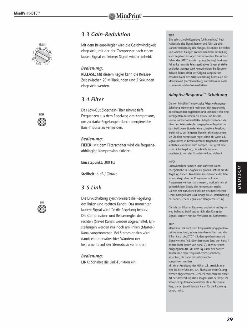
3.3 Gain-Reduktion
Mit dem Release-Regler wird die Geschwindigkeiteingestellt, mit der der Compressor nach einemlauten Signal ein leiseres Signal wieder anhebt.
Bedienung:RELEASE: Mit diesem Regler kann die Release-Zeit zwischen 20 Millisekunden und 2 Sekundeneingestellt werden.
3.4 Filter
Das Low-Cut Sidechain-Filter nimmt tiefeFrequenzen aus dem Regelweg des Kompressors,um zu starke Regelungen durch energiereicheBass-Impulse zu vermeiden.
Bedienung:FILTER: Mit dem Filterschalter wird die frequenz-abhängige Kompression aktiviert.
Einsatzpunkt: 300 Hz
Steilheit: 6 dB / Oktave
3.5 Link
Die Linkschaltung synchronisiert die Regelungdes linken und rechten Kanals. Das momentanlautere Signal wird für die Regelung benutzt. Die Compression- und Releaseregler des rechten (Slave) Kanals werden abgeschaltet, Ein-stellungen werden nur noch am linken (Master-)Kanal vorgenommen. Bei Stereosignalen wirddamit ein unerwünschtes Wandern derInstrumente auf der Stereobasis verhindert.
Bedienung:LINK: Schaltet die Link-Funktion ein.
TIPPEine sehr schnelle Regelung (Linksanschlag) hebtHallanteile des Signals hervor und führt zu einerstarken Verdichtung des Klanges. Besonders bei tiefenund weichen Klängen können bei dieser Einstellungauch Regelverzerrungen hörbar werden. Das ist keinFehler des DTCTM, sondern prinzipbedingt. In diesemFall sollte man die Releasezeit etwas länger einstellenund/oder weniger stark komprimieren. Bei längerenRelease-Zeiten bleibt der Originalklang stärkererhalten. Dank der Adaptivschaltung führt auch derMaximalwert (Rechtsanschlag) normalerweise nichtzu unerwünschten Nebeneffekten.
AdaptiveResponseTM-Schaltung
Die von MindPrint® entwickelte AdaptiveResponse-Schaltung arbeitet mit mehreren, sich gegenseitigbeeinflussenden Regelzeiten und verhindert mit einerintelligenten Automatik für Attack und Releaseunerwünschte Nebeneffekte. Adaptiv verändert dieüber den Release-Regler vorgegebene Regelzeit so,dass bei kurzen Signalen eine schnellere Regelungerzielt wird, bei längeren Signalen eine langsamere. Ein üblicher Kompressor regelt dann ab, wenn z.B.Signalspitzen in bereits dichtem, tragenden Materialauftreten, es kommt zum Pumpen. Hier greift einezusätzliche Regelung, die schnelle Impulse unabhängig von der Grundeinstellung abfängt.
INFOUnerwünschtes Pumpen kann auftreten wennenergiereiche Bass-Signale zu großen Einfluss auf dieRegelung haben. Aus diesem Grund wurde das Filterso ausgelegt, dass der Kompressor auf tiefeFrequenzen weniger stark reagiert, wodurch sich eingehörrichtiger Einsatz der Kompression ergibt. Da hier eine natürliche Funktion des menschlichenOhres nachgebildet wird, bringt diese Filterschaltungbei nahezu jedem Signal eine Klangverbesserung.
Da sich das Filter im Regelweg und nicht im Signal-weg befindet, beinflusst es nicht den Klang desSignals, sondern nur das Verhalten des Kompressors.
TIPPMan kann Link auch zum frequenzabhängigen Kom-primieren nutzen, indem man den rechten und denlinken Kanal des DTCTM mit dem gleichen (mono-)Signal versieht (z.B. über den Insert Send von Kanal 1in den Insert Return von Kanal 2), aber nur einenAusgang benutzt. Mit dem Equalizer des zweitenKanals kann man Frequenzbereiche anheben/-absenken, die dann stärker/schwächer komprimiert werden. Mit einer Anhebung der Höhen z.B. errreicht maneine De-Esserfunktion, d.h. Zischlaute beim Gesangwerden abgeschwächt. Generell muß man bei dieserArt der Anwendung dafür sorgen, dass der Pegel imSteuer- (EQ-) Kanal etwas höher als im Nutzkanalliegt, da der jeweils lautere Kanal für die Regelungbenutzt wird.
30
MindPrint-DTCTM
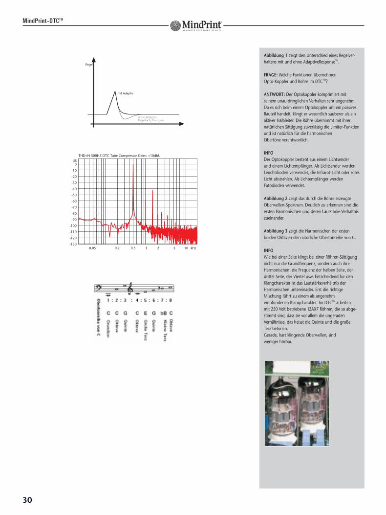
Abbildung 1 zeigt den Unterschied eines Regelver-haltens mit und ohne AdaptiveResponseTM.
FRAGE: Welche Funktionen übernehmen Opto-Koppler und Röhre im DTCTM?
ANTWORT: Der Optokoppler komprimiert mitseinem unaufdringlichen Verhalten sehr angenehm.Da es sich beim einem Optokoppler um ein passivesBauteil handelt, klingt er wesentlich sauberer als einaktiver Halbleiter. Die Röhre übernimmt mit ihrernatürlichen Sättigung zuverlässig die Limiter-Funktionund ist natürlich für die harmonischen Obertöne verantwortlich.
INFODer Optokoppler besteht aus einem Lichtsender und einem Lichtempfänger. Als Lichtsender werdenLeuchtdioden verwendet, die Infrarot-Licht oder rotesLicht abstrahlen. Als Lichtempfänger werdenFotodioden verwendet.
Abbildung 2 zeigt das durch die Röhre erzeugteOberwellen-Spektrum. Deutlich zu erkennen sind dieersten Harmonischen und deren Lautstärke-Verhältniszueinander.
Abbildung 3 zeigt die Harmonischen der erstenbeiden Oktaven der natürliche Obertonreihe von C.
INFOWie bei einer Saite klingt bei einer Röhren-Sättigungnicht nur die Grundfrequenz, sondern auch ihreHarmonischen: die Frequenz der halben Seite, derdrittel Seite, der Viertel usw. Entscheidend für denKlangcharakter ist das Lautstärkeverhältnis derHarmonischen untereinader. Erst die richtigeMischung führt zu einem als angenehmempfundenen Klangcharakter. Im DTCTM arbeiten mit 250 Volt betriebene 12AX7 Röhren, die so abge-stimmt sind, dass sie vor allem die ungeradenVerhältnisse, das heisst die Quinte und die große Terz betonen. Gerade, hart klingende Oberwellen, sind weniger hörbar.
31
DE
UT
SC
H
MindPrint-DTCTM
4. Ausgangssektion
4.1 Master Level
Der Output-Regler bestimmt die Ausgangs-laustärke des DTCTM. Er wirkt sich sowohl auf denanalogen als auch auf den optionalen Digital-ausgang aust.
Anschluss:Der symmetrische XLR-Ausgang dient alsRecording-Out für nachfolgende Aufnahme-systeme, Mischpulte oder externe Wandler. Der unsymmetrische Klinkenausgang ist alsanaloger Monitorausgang gedacht.
ACHTUNG: Der Pegel des unsym-metrischen Klinkenausgangs ist um 2 dB geringer als der des sym-metrischen XLR-Ausgangs. Diese Differenz ist technisch bedingt, für Monitoring-Zweckejedoch unbedeutend.
Bedienung:OUTPUT: Regelt die Ausgangslautstärke imBereich -8 bis +6 dB. Bei 0 herrscht Unity-Gain.
Vorsicht: Der Output-Regler wirkt nachdem Limiter. Werden mit Full-Scalelimitierte Signale noch weiter verstärkt,drohen Übersteuererungen. Ein Über-steuerungsschutz der Digitaloption istdann nicht mehr gewährleistet!
4.2 Bypass
Bedienung:Bypass: Schaltet alle Bearbeitungsstufen des DTCTM
und den Output-Regler aus dem Signalweg.
Vorsicht: Je nach Einstellung derBearbeitungsstufen hat dasbearbeitete Signal zum Original einen hohen Pegelunterschied.
INFOIn Stellung 0 wird die Digitaloption optimal ange-steuert. Limitiert man nun bei 0 dB Fullscale wird dieDynamik des Wandlers voll ausgenutzt. KritischesMaterial sollte allerdings auch bei Fullscale-Limitingmit etwas weniger als 0 dB ausgesteuert werden. Die rote LED sollte auch bei Signal-Spitzen nicht aufleuchten.
TIPPDie Meter lassen sich auf Eingang und Ausgangschalten. Es kann also der Pegel nach dem Vorver-stärker oder am Ausgang des DTCTM angezeigtwerden. Für eine optimale Aussteuerung sind zweiFälle zu berücksichtigen. Je nach dem, ob Sie deneingebauten Kompressor/Limiter benutzen odernicht. Bei Benutzung des Kompressor/Limiters solltenSie zunächst die Aussteuerungsanzeige auf Inputschalten und dann mit dem Eingangs-Gainregler beieiner Probe an einer lauten Stelle des aufzunehmen-den Stücks so aussteuern, dass die ersten gelben LEDsbei Signalspitzen aufleuchten. Dann schalten Sie dieAussteuerungsanzeige auf Output und nehmen diegewünschten klanglichen Einstellungen vor. DerKompressor/Limiter verhindert ab der mittleren Thres-holdstellung zuverlässig Übersteuerungen undberücksichtigt dabei auch evtl. Pegelanhebungen imEqualizer, so dass auch dieser nicht übersteuert wird.
Ohne Benutzung des Kompressors/Limiters schaltenSie die Aussteuerungssanzeige direkt auf Output,nehmen die gewünschten klanglichen Einstellungenvor und korrigieren die Aussteuerung mit dem InputGain Regler. Sie sollten dazu den Output-Regler inder Mittelstellung belassen. Starke Absenkungen imEqualizer sollten Sie durch eine Anhebung mit demOutput Gain Regler ausgleichen, sonst laufen SieGefahr, den Equalizer durch zu hohe Eingangspegelzu übersteuern.
TIPPBypass dient hauptsächlich dem Vergleich desbearbeiteten Signals mit dem Original. Wird derOutput-Regler als Lautstärke-Regler zweckentfremdet,sollte man vor allem bei Absenkungen beachten, dass das Original-Signal einen wesentlich höherenPegel führen kann als die Bearbeitung. Um nachge-schaltete Geräte zu schützen ist es in diesem Fallsinnvoll, die einzelnen Bearbeitungsstufen zum Vergleich auszuschalten.
LINE OUT A
BALANCEDUNBALANCEDMONITOR
max. Eingangspegel: +22 dBuSignaldynamik: 117 dB
Ausgänge:
LINE OUT XLR:Bauart: elektronisch symmtriert
& floatingImpedanz: 220 Ωmax. Ausgangspegel: + 25 dBu
LINE OUT Klinke:Bauart Ausgang: unsymmetriertImpedanz: 220 Ωmax. Ausgangspegel: + 22,5 dBu
INSERT SEND:Bauart: elektronisch symmtriert
& floatingAusgangsimpedanz: 220 Ωmax. Ausgangspegel: + 22 dBu
Frequenzbearbeitung:
LO CUT:Einsatzfrequenz: 22 Hz bis 220 HzSteilheit: 24 dB/ oct.HI CUT:Einsatzfrequenz: 3 kHz bis 30 kHzSteilheit: 12 dB/ oct.LF FILTER:Typ: ShelvingEinsatzfrequenz: 22 Hz - 700 Hz Anhebung: +15 dB Absenkung: -15 dBGüte - Steilheit: Q=0,15 bis Q=3 LMF FILTER:Typ: BellEinsatzfrequenz: 47 Hz - 1600 Hz Anhebung: +15 dB Absenkung: -25 dBGüte - Bandbreite: Q=0,15 – Q=3 HMF FILTER:Typ: BellEinsatzfrequenz: 190 Hz - 13000 Hz Anhebung: +15 dB Absenkung: -25 dBGüte - Bandbreite: Q=0,15 – Q=3
32
MindPrint-DTCTM
5. TechnischeDaten
Klassifikation: MIC/ LINE/ Instrument Pre-amp mit EQ und Röhrenkompressor.
Dieses Gerät ist zweikanalig gebaut. Alle Messdaten beschreiben nur einenKanal. Die Daten des zweiten Kanalskönnen als gleich betrachtet werden. Alle Pegelangaben beziehen sich auf 0 dBu (0,775V RMS ).
Eingänge :
LINE IN:Bauart: elektronisch symmtriert
& floatingImpedanz: 35 kΩEmpfindlichkeit: -12dBU bis +20 dBumax. Eingangspegel: + 25,5 dBuStörspannungsabstand: -106 dB Signaldynamik: 123 dB
MIC. IN:Bauart: Trafo-symmetriert
& flotingFrequenzbandbreite: 5Hz bis 127kHz
+/- 3dB Eingangsimpedanz: 5 kΩEmpfindlichkeit: -68dBu bis +22dBumax. Eingangspegel: + 30 dBu bei –20dBONStörspannungsabstand: -131 dB
INSTRUMENT. IN:Bauart: unsymmetrischImpedanz: 2,2 MΩEmpfindlichkeit: -35dBu bis +3dBumax. Eingangspegel: +7 dBuStörspannungsabstand: -120,5 dB Signaldynamik: 118 dB
INSERT RET.:Bauart: elektronisch symmtriert
& floatingImpedanz: 44 kΩEmpfindlichkeit: 0 dBu
HF FILTER:Typ: ShelvingEinsatzfrequenz: 840 Hz - 30000 Hz Anhebung: +15 dB Absenkung: -15 dBGüte - Steilheit: Q=0,15 bis Q=3
Dynamik-Bearbeitung:
Limit: +12dBFs bis 0dBFs.Attackzeit : 5 ms 50msReleasezeit : 20 ms bis 2000 msFilter: Low-Cut 300 Hz,
6dB pro Oktave Master Sektion:Output Level: - ∞ dB bis +6dBBypass: entfernt EQ,
Compressor/Limiter, Insert und Master Sektion aus dem Signalweg
Allgemeine elektrischeDaten:
max. Stromaufnahme: 190 mA@ 230Vmax. Leistungsaufnahme: 44 VANetzspannungsbereich: +/- 10 %Umgebungstemperaturbereich: - 10 °C bis
+ 60 °C
Allgemeine mechanischeDaten:
Abmessungen: Breite: 482 mm Höhe: 133 mm Tiefe:238 mm
Rackmaße: 19 ", 1 HEEinbautiefe: 222 mm, Bedientiefe: 23 mmGewicht: 6,1 kg
(6,5 kg mit DI- MOD)
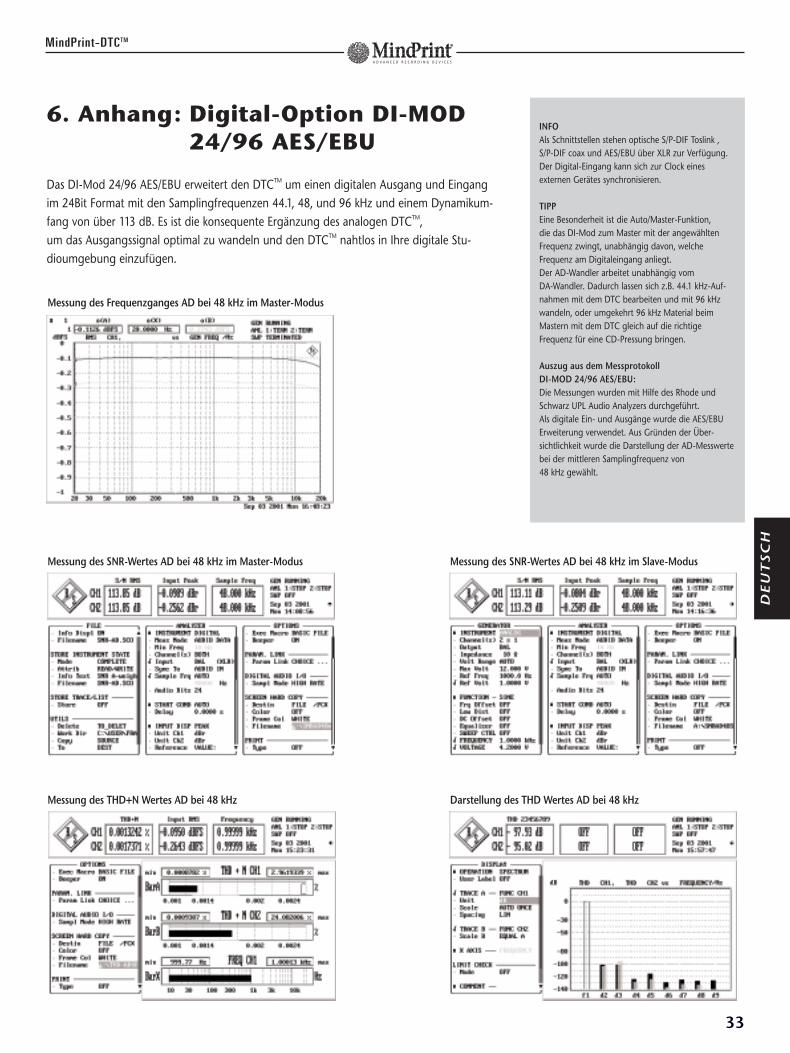
MindPrint-DTCTM
33
6. Anhang: Digital-Option DI-MOD24/96 AES/EBU
Das DI-Mod 24/96 AES/EBU erweitert den DTCTM um einen digitalen Ausgang und Eingang im 24Bit Format mit den Samplingfrequenzen 44.1, 48, und 96 kHz und einem Dynamikum-fang von über 113 dB. Es ist die konsequente Ergänzung des analogen DTCTM, um das Ausgangssignal optimal zu wandeln und den DTCTM nahtlos in Ihre digitale Stu-dioumgebung einzufügen.
INFOAls Schnittstellen stehen optische S/P-DIF Toslink ,S/P-DIF coax und AES/EBU über XLR zur Verfügung.Der Digital-Eingang kann sich zur Clock einesexternen Gerätes synchronisieren.
TIPPEine Besonderheit ist die Auto/Master-Funktion,die das DI-Mod zum Master mit der angewähltenFrequenz zwingt, unabhängig davon, welcheFrequenz am Digitaleingang anliegt. Der AD-Wandler arbeitet unabhängig vom DA-Wandler. Dadurch lassen sich z.B. 44.1 kHz-Auf-nahmen mit dem DTC bearbeiten und mit 96 kHzwandeln, oder umgekehrt 96 kHz Material beimMastern mit dem DTC gleich auf die richtigeFrequenz für eine CD-Pressung bringen.
Auszug aus dem Messprotokoll DI-MOD 24/96 AES/EBU:Die Messungen wurden mit Hilfe des Rhode undSchwarz UPL Audio Analyzers durchgeführt. Als digitale Ein- und Ausgänge wurde die AES/EBUErweiterung verwendet. Aus Gründen der Über-sichtlichkeit wurde die Darstellung der AD-Messwertebei der mittleren Samplingfrequenz von 48 kHz gewählt.
Messung des Frequenzganges AD bei 48 kHz im Master-Modus
Messung des SNR-Wertes AD bei 48 kHz im Master-Modus Messung des SNR-Wertes AD bei 48 kHz im Slave-Modus
Messung des THD+N Wertes AD bei 48 kHz Darstellung des THD Wertes AD bei 48 kHz
DE
UT
SC
H
IMPORTANT SAFETY INSTRUCTIONSBEFORE CONNECTING, READ INSTRUCTIONS
• Read all of these instructions!
• Save these instructions for later use!
• Follow all warnings and instructions marked on the product!
• Do not use this product near water, i.e. bathtub, sink, swimming pool, wet basement, etc.
• Do not place this product on an unstable cart, stand or table. The product may fall, causing
serious damage to the product or to persons!
• Slots and openings in the cabinet and the back or bottom are provided for ventilation; to
ensure reliable operation of the product and to protect it from overheating, these openings
must not be blocked or covered. This product should not be placed in a built-in installation
unless proper ventilation is provided.
• This product should not be placed near a source of heat such as a stove, radiator, or
another heat producing amplifier.
• Use only the supplied power supply or power cord. If you are not sure of the type of power
available, consult your dealer or local power company.
• Do not allow anything to rest on the power cord. Do not locate this product where persons
will walk on the cord.
• Never break off the ground pin on the power supply cord.
• Power supply cords should always be handled carefully. Periodically check cords for cuts or
sign of stress, especially at the plug and the point where the cord exits the unit.
• The power supply cord should be unplugged when the unit is to be unused for long periods
of time.
• If this product is to be mounted in an equipment rack, rear support should be provided.
• This product should be used only with a cart or stand that is recommended by HK AUDIO.
• Never push objects of any kind into this product through cabinet slots as they may touch
dangerous voltage points or short out parts that could result in risk of fire or electric shock.
Never spill liquid of any kind on the product.
• Do not attempt to service this product yourself, as opening or removing covers may expose
you to dangerous voltage points or other risks. Refer all servicing to qualified service
personnel.
• Unplug this product from the wall outlet and refer servicing to qualified service personnel
under the following conditions:
• When the power cord or plug is damaged or frayed.
• If liquid has been spilled into the product.
• If the product has been exposed to rain or water.
• If the product does not operate normally when the operating instructions are followed.
• If the product has been dropped or the cabinet has been damaged.
• If the product exhibits a distinct change in performance, indicating a need of service!
• Adjust only these controls that are covered by the operating instructions since improper
adjustment of other controls may result in damage and will often require extensive work by
a qualified technician to restore the product to normal operation.
• Exposure to extremely high noise levels may cause a permanent hearing loss.
• Individuals vary considerably in susceptibility to noise induced hearig loss, but nearly
everyone will lose some hearing if exposed to sufficiently intense noise for a sufficient time.
The U.S. Government´s Occupational Safety and Health Administration (OSHA) has specified
the following permissible noise level exposures:
Duration Per Day In Hours Sound LeveldBA, Slow Response8 906 924 953 972 100
11/2 1021 105
1/2 1101/4 or less 115
• According to OSHA, any exposure in excess of the above permissible limits could result in
some hearing loss.
• Ear plug protectors in the ear canals or over the ears must be worn when operating this
amplification system in order to prevent a permanent hearing loss if exposure is in excess
of the limits as set forth above. To ensure against potentially dangerous exposure to high
sound pressure levels, it is recommended that all persons exposed to equipment capable of
producing high sound pressure levels such as this amplification system be protected by
hearing protectors while this unit is in operation.
• Fuses: Replace with IEC 127 (5x 20 mms) type and rated fuse for best performance only.
TO PREVENT THE RISK OF FIRE AND SHOCK HAZARD, DO NOT EXPOSE THIS APPLIANCE TOMOISTURE OR RAIN. DO NOT OPEN CASE; NO USER SERVICE-ABLE PARTS INSIDE.REFER SERVICING TO QUALIFIED SERVICE PERSONNEL.
WICHTIGE SICHERHEITSHINWEISE!BITTE VOR GEBRAUCH LESEN UND FÜR SPÄTEREN GEBRAUCH AUFBEWAHREN!
• Das Gerät wurde von HK AUDIO gemäß IEC 9239 gebaut und hat das Werk in sicherheits-
technisch einwandfreiem Zustand verlassen. Um diesen Zustand zu erhalten und einen
gefahrlosen Betrieb sicherzustellen, muss der Anwender die Hinweise und die Warnvermerke
beachten, die in der Bedienungsanleitung enthalten sind. Das Gerät entspricht der Schutz-
klasse I (schutzgeerdet).
• DIE SICHERHEIT, ZUVERLÄSSIGKEIT UND LEISTUNG DES GERÄTES WIRD VON
HK AUDIO NUR DANN GEWÄHRLEISTET WENN:
• Montage, Erweiterung, Neueinstellung, Änderungen oder Reparaturen von HK AUDIO oder
von dazu ermächtigten Personen ausgeführt werden.
• die elektrische Installation des betreffenden Raumes den Anforderungen von IEC (ANSI)-
Festlegungen entspricht.
• das Gerät in Übereinstimmung mit der Gebrauchsanweisung verwendet wird.
WARNUNG:• Wenn Abdeckungen geöffnet oder Gehäuseteile entfernt werden, außer wenn dies von Hand
möglich ist, können Teile freigelegt werden, die Spannung führen.• Wenn ein Öffnen des Gerätes erforderlich ist, muss das Gerät von allen Spannungsquellen
getrennt sein. Berücksichtigen Sie dies vor dem Abgleich, vor einer Wartung, vor einerInstandsetzung und vor einem Austausch von Teilen.
• Ein Abgleich, eine Wartung oder eine Reparatur am geöffneten Gerät unter Spannung darfnur durch eine vom Hersteller autorisierte Fachkraft (nach VBG 4) geschehen, die mit denverbundenen Gefahren vertraut ist.
• Lautsprecher-Ausgänge, die mit dem IEC 417/5036-Zeichen (Abb.1, s.unten) versehen sind,können berührungsgefährliche Spannungen führen. Deshalb vor dem Einschalten des Gerä-tes Verbindung nur mit dem vom Hersteller empfohlenen Anschlusskabel zum Lautsprecherherstellen.
• Alle Stecker an Verbindungskabeln müssen mit dem Gehäuse verschraubt oder verriegeltsein, sofern möglich.
• Es dürfen nur Sicherungen vom angegebenen Typ und der angegebenen Nennstromstärke alsErsatz verwendet werden.
• Eine Verwendung von geflickten Sicherungen oder Kurzschließen des Halters ist unzulässig.• Niemals die Schutzleiterverbindung unterbrechen.• Oberflächen, die mit dem „HOT“-Zeichen (Abb.2, s.unten) versehen sind, Rückwände oder
Abdeckungen mit Kühlschlitzen, Kühlkörper und deren Abdeckungen sowie Röhren undderen Abdeckungen können im Betrieb erhöhte Temperaturen annehmen und sollten deshalbnicht berührt werden.
• Hohe Lautstärkepegel können dauernde Gehörschäden verursachen. Vermeiden Sie deshalbdie direkte Nähe von Lautsprechern, die mit hohen Pegeln betrieben werden. Verwenden Sieeinen Gehörschutz bei dauernder Einwirkung hoher Pegel.
NETZANSCHLUSS:• Das Gerät ist für Dauerbetrieb ausgelegt.• Die eingestellte Betriebsspannung muß mit der örtlichen Netzspannung übereinstimmen.• Der Anschluss an das Stromnetz erfolgt mit dem mitgelieferten Netzteil oder Netzkabel.• Netzteil: Eine beschädigte Anschlussleitung kann nicht ersetzt werden. Das Netzteil darf
nicht mehr betrieben werden.• Vermeiden Sie einen Anschluss an das Stromnetz in Verteilerdosen zusammen mit vielen
anderen Stromverbrauchern.• Die Steckdose für die Stromversorgung muß nahe am Gerät angebracht und leicht
zugänglich sein.
AUFSTELLUNGSORT:• Das Gerät sollte nur auf einer sauberen, waagerechten Arbeitsfläche stehen.• Das Gerät darf während des Betriebs keinen Erschütterungen ausgesetzt sein.• Feuchtigkeit und Staub sind nach Möglichkeit fernzuhalten.• Das Gerät darf nicht in der Nähe von Wasser, Badewanne, Waschbecken, Küchenspüle, Nass-
raum, Swimmingpool oder feuchten Räumen betrieben werden. Keine mit Flüssigkeit gefüll-ten Gegenstände (Vase, Gläser, Flaschen etc.) auf das Gerät stellen.
• Sorgen Sie für ausreichende Belüftung der Geräte.• Eventuelle Ventilationsöffnungen dürfen niemals blockiert oder abgedeckt werden. Das
Gerät muss mindestens 20 cm von Wänden entfernt aufgestellt werden. Das Gerät darf nurdann in ein Rack eingebaut werden, wenn für ausreichende Ventilation gesorgt ist und dieEinbauanweisungen des Herstellers eingehalten werden.
• Vermeiden Sie direkte Sonneneinstrahlung sowie die unmittelbare Nähe von Heizkörpernund Heizstrahlern oder ähnlicher Geräte.
• Wenn das Gerät plötzlich von einem kalten an einen warmen Ort gebracht wird, kann sichim Geräteinnern Kondensfeuchtigkeit bilden. Dies ist insbesondere bei Röhrengeräten zubeachten. Vor dem Einschalten solange warten bis das Gerät Raumtemperatur angenommenhat.
• Zubehör: Das Gerät nicht auf einen instabilen Wagen, Ständer, Dreifuß, Untersatz oder Tischstellen. Wenn das Gerät herunterfällt kann es Personenschäden verursachen und selbstbeschädigt werden. Verwenden Sie das Gerät nur mit einem vom Hersteller empfohlenenoder zusammen mit dem Gerät verkauften Wagen, Rack, Ständer, Dreifuß oder Untersatz. Beider Aufstellung des Gerätes müssen die Anweisungen des Herstellers befolgt und muss dasvom Hersteller empfohlene Aufstellzubehör verwendet werden. Eine Kombination aus Gerätund Gestell muß vorsichtigt bewegt werden. Plötzliches Anhalten, übermäßige Kraftanwen-dung und ungleichmäßige Böden können das Umkippen der Kombination aus Gerät undGestell bewirken.
• Zusatzvorrichtungen: Verwenden Sie niemals Zusatzvorrichtungen, die nicht vom Herstellerempfohlen wurden, weil dadurch Unfälle verursacht werden können
• Zum Schutz des Gerätes bei Gewitter oder wenn es längere Zeit nicht beaufsichtigt oderbenutzt wird, sollte der Netzstecker gezogen werden. Dies verhindert Schäden am Gerätaufgrund von Blitzschlag und Spannungsstößen im Wechselstromnetz.
Abb.1 Abb.2
34
IMPORTANT ADVICE ON SAFETY!PLEASE READ BEFORE USE AND KEEP FOR LATER USE!
• The unit has been built by HK AUDIO in accordance with IEC 9239 and left the factory insafe working order. To maintain this condition and ensure non-risk operation, the user mustfollow the advice and warning comments found in the operating instructions. The unitconforms to Protection Class 1 (protectively earthed).
• HK AUDIO ONLY GUARANTEE THE SAFETY, RELIABILITY AND EFFICIENCY OF THE UNIT IF:• Assembly, extension, re-adjustment, modifications or repairs are carried out by HK AUDIO or
by persons authorized to do so.• The electrical installation of the relevant area complies with the requirements of IEC (ANSI)
specifications.• The unit is used in accordance with the operating instructions.• The unit is regularly checked and tested for electrical safety by a competent technician.
WARNING:• If covers are opened or sections of casing are removed, except where this can be done
manually, live parts can become exposed.• If it is necessary to open the unit this must be isolated from all power sources. Please take
this into account before carrying out adjustments, maintenance, repairs and beforereplacing parts.
• Adjustment, maintenance and repairs carried out when the unit has been opened and is stilllive may only be performed by specialist personnel who are authorized by the manufacturer(in accordance with VBG 4) and who are aware of the associated hazards.
• Loudspeaker outputs which have the IEC 417/5036 symbol (Diagram 1, below) can carryvoltages which are hazardous if they are made contact with. Before the unit is switched on,the loudspeaker should therefore only be connected using the lead recommended by themanufacturer.
• Where possible, all plugs on connection cables must be screwed or locked onto the casing.• Replace with IEC 127 (5x 20 mms) type and rated fuse for best performance only.• It is not permitted to use repaired fuses or to short-circuit the fuse holder.• Never interrupt the protective conductor connection.• Surfaces which are equipped with the „HOT“ mark (Diagram 2, below), rear panels or
covers with cooling slits, cooling bodies and their covers, as well as tubes and their coversare purposely designed to dissipate high temperatures and should therefore not be touched.
• High loudspeaker levels can cause permanent hearing damage. You should therefore avoidthe direct vicinity of loudspeakers operating at high levels. Wear hearing protection ifcontinuously exposed to high levels.
MAINS CONNECTION:• The unit is designed for continuous operation.• The set operating voltage must match the local mains supply voltage.• The unit is connected to the mains via the supplied power unit or power cable.• Power unit: Never use a damaged connection lead. Any damage must be rectified by a
competent technician.• Avoid connection to the mains supply in distributor boxes together with several other
power consumers.• The plug socket for the power supply must be positioned near the unit and must be easily
accessible.
PLACE OF INSTALLATION:• The unit should stand only on a clean, horizontal working surface.• The unit must not be exposed to vibrations during operation.• Keep away from moisture and dust where possible.• Do not place the unit near water, baths, wash basins, kitchen sinks, wet areas, swimming
pools or damp rooms. Do not place objects containing liquid on the unit - vases, glasses,bottles etc.
• Ensure that the unit is well ventilated.• Any ventilation openings must never be blocked or covered. The unit must be positioned at
least 20 cm away from walls. The unit may only be fitted in a rack if adequate ventilation isensured and if the manufacturer’s installation instructions are followed.
• Keep away from direct sunlight and the immediate vicinity of heating elements and radiantheaters or similar devices.
• If the unit is suddenly moved from a cold to a warm location, condensation can form insideit. This must be taken into account particularly in the case of tube units. Before switchingon, wait until the unit has reached room temperature.
• Accessories: Do not place the unit on an unsteady trolley, stand, tripod, base or table. If theunit falls down, it can cause personal injury and itself become damaged. Use the unit onlywith the trolley, rack stand, tripod or base recommended by the manufacturer or purchasedtogether with the unit. When setting the unit up, all the manufacturer’s instructions must befollowed and the setup accessories recommended by the manufacturer must be used. Anycombination of unit and stand must be moved carefully. A sudden stop, excessive use offorce and uneven floors can cause the combination of unit and stand to tip over.
• Additional equipment: Never use additional equipment which has not been recommendedby the manufacturer as this can cause accidents.
• To protect the unit during bad weather or when left unattended for prolonged periods, themains plug should be disconnected. This prevents the unit being damaged by lightning andpower surges in the AC mains supply.
Diagram 1 Diagram 2
CONSEILS DE SECURITE IMPORTANTS!PRIERE DE LIRE AVANT L’EMPLOI ET A CONSERVER POUR UTILISATION ULTERIEURE!
• L’appareil a été conçu par HK AUDIO selon la norme IEC 9239 et a quitté l’entreprise dansun état irréprochable. Afin de conserver cet état et d’assurer un fonctionnement sansdanger de l’appareil nous conseillons à l’utilisateur la lecture des indications de sécuritécontenues dans le mode d’emploi. L’appareil est conforme à la classification I (mise à terrede protection).
• SURETE, FIABILITE ET EFFICACITE DE L’APPAREIL NE SONT GARANTIS PAR HK AUDIO QUE SI:• Montage, extension, nouveau réglage, modification ou réparation sont effectués par
HK AUDIO ou par toute personne autorisée par HK AUDIO.• L’installation électrique de la pièce concernée correspond aux normes IEC (ANSI).• L’utilisation de l’appareil suit le mode d’emploi.
AVERTISSEMENT:• A moins que cela ne soit manuellement possible, tout enlèvement ou ouverture du boîtier
peut entrainer la mise au jour de pieces sous tension.• Si l’ouverture de l’appareil est nécessaire, celui-ci doit être coupé de chaque source de
courant. Ceci est à prendre en considération avant tout ajustement, entretien, réparation ouchangement de pieces.
• Ajustement, entretien ou réparation sur l’appareil ouvert et sous tension ne peuvent êtreéffectués que par un spécialiste autorisé par le fabricant (selon VBG4). Le spécialiste étantconscient des dangers liés à ce genre de réparation.
• Les sorties de baffles qui portent le signe IEC 417/5036 (fig. 1, voir en bas) peuvent êtresous tension dangereuse. Avant de brancher l’appareil utiliser uniquement le câble deraccordement conseillé par le fabricant pour raccorder les baffles.
• Toutes les prises des câbles de raccordement doivent être, si possible, vissées ouverrouillées sur le boîtier.
• Utilisez subsidiairement uniquement des fusibles de type et de puissance de courantnominale donnés.
• L’utilisation de fusibles rafistolés ou court-circuites est inadmissible.• Ne jamais interrompre la connexion du circuit protecteur.• Il est conseillé de ne pas toucher aux surfaces pourvues du signe „HOT“ (fig. 2, voir en
bas), aux parois arrières ou caches munis de fentes d’aération, éléments d’aération et leurscaches ansi qu’aux tubes et leurs caches. Ces éléments pouvant atteindre des températuresélévées pendant l’utilisation de l’appareil.
• Les Niveaux de puissance élévés peuvent entrainer des lésions auditives durables. Evitezdonc la proximité de haut-parleurs utilisés à haute puissance. Lors de haute puissancecontinue utilisez une protection auditive.
BRANCHEMENT SUR LE SECTEUR:• L’appareil est conçu pour une utilisation continue.• La tension de fonctionnement doit concorder avec la tension secteur locale.• Le raccordement au réseau éléctrique s’effectue avec l’adaptateur ou le cordon
d´alimentation livré avec l’appareil.• Adaptateur: Un câble de raccordement abimé ne peut être remplacé. L’adaptateur est
inutilisable.• Evitez un raccordement au réseau par des boîtes de distribution surchargées.• La prise de courant doit être placée à proximité de l’appareil et facile à atteindre.
LIEU D’INSTALLATION:• L’appareil doit être placé sur une surface de travail propre et horizontale.• L’appareil en marche ne doit en aucun cas subir des vibrations.• Evitez dans la mesure du possible poussière et humidité.• L’appareil ne doit pas être placé à proximité d’eau, de baignoire, lavabo, évier, pièce d’eau,
piscine ou dans une pièce humide. Ne placez aucun vase, verre, bouteille ou tout objetrempli de liquide sur l’appareil.
• L’appareil doit être suffisamment aéré.• Ne jamais recouvrir les ouvertures d’aération. L’appareil doit être placé à 20 cm du mur au
minimum. L’appareil peut être monté dans un Rack si une ventilation suffisante est possibleet si les conseils de montage du fabricant sont suivis.
• Evitez les rayons de soleil et la proximité de radiateurs, chauffages etc.• Une condensation d’eau peut se former dans l’appareil si celui-ci est transporté
brusquement d’un endroit froid à un endroit chaud. Ceci est particulièrement importantpour des appareils à tubes. Avant de brancher l’appareil attendre qu’il ait la températureambiante.
• Accessoires: L’appareil ne doit être placé sur un chariot, support, trépied, bâti ou tableinstable. Une chute de l’appareil peut entrainer aussi bien des dommages corporels quetechniques. Utilisez l’appareil uniquement avec un chariot, Rack, support, trépied ou bâticonseillé par le fabricant ou vendu en combinaison avec l’appareil. Les indications dufabricant pour l’installation de l’appareil sont à suivre, et les accessoires d’installationconseillés par le fabricant sont à utiliser. Un ensemble support et appareil doit être déplacéavec précaution. Des mouvements brusques et des revêtements de sol irreguliers peuvententrainer la chute de l´ensemble.
• Equipements supplémentaires: Ne jamais utiliser un équipement supplémentaire n’ayant pasété conseillé par le fabricant, ceci pouvant entrainer des accidents.
• Afin de protéger l’appareil pendant un orage ou s’il ne doit pas être utilisé pendant uncertain temps, il est conseillé d’enlever la prise au secteur. Ceci évite des dommages dûs àla foudre ou à des coups de tension dans le réseau à courant alternatif.
Fig. 1 Fig. 2
35
IMPORTANTI AVVERTIMENTI DI SICUREZZA!Leggere attentamente prima dell’uso e conservare per un utilizzo successivo:• L’apparecchio è stato costruito dalla HK AUDIO secondo la normativa europea IEC 9239 ed
ha lasciato il nostro stabilimento in stato ineccepibile. Per garantire il mantenimento di talestato e un utilizzo assolutamente privo di rischi l’utente è tenuto ad osservare le indicazionie gli avvertimenti di sicurezza contenuti nelle istruzioni per l’uso. L’apparecchio rispecchia illivello di sicurezza I (collegato a terra).
• Sicurezza, affidabilità e prestazioni dell’apparecchio vengono garantiti dalla HK AUDIO soloed esclusivamente se:
• Montaggio, ampliamento, rimessa a punto, modifiche e riparazioni vengono eseguite dallaHK AUDIO stessa o da personale da essa autorizzato.
• Gli impianti elettrici nei locali prescelti per l’uso dell’apparecchio rispondono alle normativestabilite dall’ANSI.
• L’apparecchio viene utilizzato come indicato nel libretto delle istruzioni per l’uso.
Avvertimenti:• In caso di apertura di parti di rivestimento o rimozione di parti dell’involucro, a meno che
non si tratti di pezzi rimovibili semplicemente a mano, possono venire alla luce partidell’apparecchio conduttrici di tensione.
• Se l’apertura dell’apparecchio dovesse risultare necessaria è indispensabile staccareprecedentemente quest’ultimo da tutte le fonti di tensione. Rispettare tale misura diprevenzione anche prima di un allineamento, di operazioni di manutenzione, della messa inesercizio o della sostituzione di componenti all’interno dell’apparecchio.
• Allineamento, operazioni di manutenzione o eventuali riparazioni dell’apparecchio in pre-senza di tensione vanno eseguite esclusivamente da personale specializzato ed autorizzato,in grado di eseguire tali operazioni evitandone i rischi connessi.
• Le uscite degli altoparlanti contrassegnate dai caratteri IEC 417/5036 (vedi illustrazione 1 afondo pag.) possono essere conduttrici di tensione pericolosa con cui evitare il contatto. Perquesto motivo, prima di accendere l’apparecchio, collegare quest’ultimo agli altoparlantiservendosi esclusivamente del cavetto d’allacciamento indicato dal produttore.
• Tutte le spine e i cavi di collegamento devono essere avvitati o fissati all’involucrodell’apparecchio per quanto possibile.
• Tutti i fusibili di sicurezza vanno sostituiti esclusivamente con fusibili del tipo prescritto evalore della corrente nominale indicato.
• L’utilizzo di fusibili di sicurezza non integri e la messa in corto circuito del sostegno dimetallo sono proibite.
• Non interrompere mai il collegamento con il circuito di protezione.• Superfici contrassegnate dalla parola „HOT“ (vedi illustrazione 2 a fondo pag.), cosi come
griglie di aerazione, dispositivi di raffreddamento e i loro rivestimenti di protezione, oppurevalvole e i relativi rivestimenti protettivi possono surriscaldarsi notevolmente durante l’usoe per questo motivo non vanno toccate.
• L’ascolto di suoni ad alto volume può provocare danni permanenti all’udito. Evitate perciòla diretta vicinanza con altoparlanti ad alta emissione di suono e utilizzate cuffie protettivein caso ciò non sia possibile.
Alimentazione:• L’apparecchio è concepito per il funzionamento continuo.• La tensione di esercizio deve corrispondere alla tensione di rete a cui ci si allaccia.• L’allacciamento alla rete elettrica avviene tramite alimentatore o cavetto d’alimentazione
consegnato insieme all’apparecchio.• Alimentatore: un cavo di connessione danneggiato non può essere sostituito. L’alimentatore
non può più essere utilizzato.• Evitate un allacciamento alla rete di corrente utilizzando cassette di distribuzione
sovraccariche.• La spina di corrente deve essere situata nelle vicinanze dell’apparecchio e facilmente
raggiungibile in qualsiasi momento.
Locali di collocamento:• Opportuno collocare l’apparecchio su una superficie pulita e orizzontale.• Non sottoporre l’apparecchio in funzione a scosse e vibrazioni.• Proteggere l’apparecchio per quanto possibile da umidità e polvere.• Non collocare l’apparecchio vicino ad acqua, vasche da bagno, lavandini, lavelli da cucina,
locali umidi o piscine. Non appoggiare recipienti contenenti liquidi - vasi, bicchieri,bottiglie, ecc. - sull’apparecchio.
• Provvedere ad una buone aerazione dell’apparecchio.• Eventuali aperture previste per la ventilazione dell’apparecchio non vanno ne bloccate, ne
mai coperte. L’apparecchio va collocato ad almeno 20 cm di distanza dalle pareti circostantie può essere inserito tra altre componenti di un impianto solo in caso di sufficienteventilazione e qualora le direttive di montaggio del produttore vengano rispettate.
• Evitare di esporre l’apparecchio ai raggi del sole e di collocarlo direttamente nelle vicinanzedi fonti di calore come caloriferi, stufette, ecc.
• Se l’apparecchio viene trasportato rapidamente da un locale freddo ad uno riscaldato puòsuccedere che al suo interno si crei della condensa. Ciò va tenuto in considerazionesoprattutto in caso di apparecchi a valvole. Attendere che l’apparecchio abbia assunto latemperatura ambiente prima di accenderlo.
• Accessori: non collocare l’apparecchio su carrelli, supporti, treppiedi, superfici o tavoliinstabili. Se l’apparecchio dovesse cadere a terra potrebbe causare danni a terzi odanneggiarsi irreparabilmente. Utilizzate per il collocamento dell’apparecchio supporti,treppiedi e superfici che siano consigliate dal produttore o direttamente compresenell’offerta di vendita. Per il collocamento dell’apparecchio attenetevi strettamente alleistruzioni del produttore, utilizzando esclusivamente accessori da esso consigliati. L’appa-recchio in combinazione ad un supporto va spostato con molta attenzione. Movimenti bru-schi o il collocamento su pavimenti non piani possono provocare la caduta dell’apparecchioe del suo supporto.
• Accessori supplementari: non utilizzate mai accessori supplementari che non sianoconsigliati dal produttore, potendo essere ciò causa di incidenti.
• Per proteggere l’apparecchio in caso di temporali o nel caso questo non venisse utilizzatoper diverso tempo si consiglia di staccarne la spina di corrente. In questo modo si evitanodanni all’apparecchio dovuti a colpi di fulmine o ad improvvisi aumenti di tensione nelcircuito di corrente alternata.
Illustrazione 1 Illustrazione 2
¡INDICACIONES DE SEGURIDAD IMPORTANTES!¡LÉANSE ANTES DE UTILIZAR EL APARATO Y GUARDENSE PARA SU USO POSTERIOR!• El aparato ha sido producido por HK AUDIO según el IEC 9239 y salió de la fábrica en un
estado técnicamente perfecto. Para conservar este estado y asegurar un funcionamiento sinpeligros el usuario debe tener en cuenta las indicaciones y advertencias contenidas en lasinstrucciones de manejo. El aparato corresponde a la clase de protección l (toma de tierraprotegida).
• LA SEGURIDAD, LA FIABILIDAD Y EL RENDIMIENTO DEL APARATO SOLO ESTANGARANTIZADOS POR HK AUDIO CUANDO:
• el montaje, la ampliación, el reajuste, los cambios o las reparaciones se realicen porHK AUDIO o por personas autorizadas para ello;
• la instalación eléctrica del recinto en cuestión corresponda a los requisitos de ladeterminación del IEC (ANSI);
• el aparato se use de acuerdo con las indicaciones de uso.
ADVERTENCIA:• Si se destapan protecciones o se retiran piezas de la carcasa, exceptuando si se puede
hacer manualmente, se pueden dejar piezas al descubierto que sean conductoras detensión.
• Si es necesario abrir el aparato, éste tiene que estar aislado de todas las fuentes dealimentación. Esto se debe tener en cuenta antes del ajuste, de un entretenimiento, de unareparación y de una sustitución de las piezas.
• Un ajuste, un entretenimiento o una reparación en el aparato abierto y bajo tensión sólopuede ser llevado a cabo por un especialista autorizado por el productor (según VBG 4) queconozca a fondo los peligros que ello conlleva.
• Las salidas de altavoces que estén provistas de la característica IEC 417/5036 (figura 1,véase abajo) pueden conducir tensiones peligrosas al contacto. Por ello es indispensableque antes de poner en marcha el aparato; la conexión se haya realizado únicamente con elcable de empalmes recomendado por el productor.
• Las clavijas de contacto al final de los cables conectores tienen que estar atornilladas oenclavadas a la carcasa, en tanto que sea posible.
• Los fusibles de repuesto que se utilicen sólo pueden ser del tipo indicado y tener laintensidad nominal indicada.
• El uso de fusibles reparados o la puesta en cortocircuito del soporte es inadmisible.• El empalme del conductor de protección no se puede interrumpir en ningún caso.• Las superficies provistas de la característica "HOT" (figura 2, véase abajo), los paneles de
fondo trasero o las protecciones con ranuras de ventilación, los cuerpos de ventilación y susprotecciones, así como las válvulas electrónicas y sus protecciones pueden alcanzartemperaturas muy altas durante el funcionamiento y por ello no se deberían tocar.
• Niveles elevados de la intensidad de sonido pueden causar continuos daños auditivos; porello debe evitar acercarse demasiado a altavoces que funcionen a altos niveles. En talescasos utilice protecciones auditivas.
ACOMETIDA A LA RED:• El aparato está proyectado para un funcionamiento continuo.• La tensión de funcionamiento ajustada tiene que coincidir con la tensión de la red del lugar.• La conexión a la red eléctrica se efectuará con la fuente de alimentación o con el cable de
red que se entreguen con el aparato.• Fuente de alimentación: una linea de conexión dañada no se puede sustituir. La fuente de
alimentación no puede volver a ponerse en funcionamiento.• Evite una conexión de la red eléctrica a distribuidores con muchas tomas de corriente.• El enchufe para el suministro de corriente tiene que estar cerca del aparato y ser de fácilacceso.
SITUACION:• El aparato debería estar situado en una superficie limpia y totalmente horizontal.• El aparato no puede estar expuesto a ningún tipo de sacudidas durante su funcionamiento.• Se deben evitar la humedad y el polvo.• El aparato no puede ponerse en funcionamiento cerca del agua, la bañera, el lavamanos, la
pila de la cocina, un recinto con tuberías de agua, la piscina o en habitaciones húmedas.Tampoco se pueden poner objetos llenos de líquido - jarrones, vasos, botellas, etc. - encimade él.
• Procure que el aparato tenga suficiente ventilación.• Las aberturas de ventilación existentes no se deben bloquear ni tapar nunca. El aparato
debe estar situado como mínimo a 20 cm de la pared. El aparato sólo se puede montar enun rack, si se ha procurado la suficiente ventilación y se han cumplido las indicaciones demontaje del productor.
• Evite los rayos del sol directos así como la proximidad a radiadores, electro-radiadores oaparatos similares.
• Si el aparato pasa repentinamente de un lugar frío a otro caliente, se puede condensarhumedad en su interior. Esto se debe tener en cuenta sobretodo en los aparatos conválvulas electrónicas. Antes de poner en marcha el aparato se debe esperar hasta que éstehaya adquirido la temperatura ambiental.
• Accesorios: el aparato no se puede colocar encima de carros, estantes, trípodes, soportes omesas inestables. Si el aparato se cae puede causar daños personales y se puede estropear.Coloque el aparato sólo en un carro, rack, estante, trípode o soporte recomendado por elproductor o que se le haya vendido junto con el aparato. En la instalación se deben seguirlas indicaciones del productor así como utilizar los accesorios recomendados por el mismopara colocarlo encima. El conjunto del aparato con el pedestal se debe mover con muchocuidado. Un paro brusco, la aplicación de una fuerza desmesurada o un suelo irregularpuede ocasionar la caida de todo el conjunto.
• Piezas adicionales: no utilice nunca piezas adicionales que no estén recomendadas por elproductor, ya que se podrían provocar accidentes.
• Para protejer el aparato de una tormenta o si no se supervisa ni utiliza durante algúntiempo, se debería desconectar la clavija de la red. Así se evitan daños en el aparato acausa de un rayo y golpes de tensión en la red de corriente alterna.
Figura 1 Figura 236
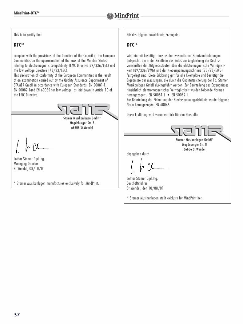
MindPrint-DTCTM
Für das folgend bezeichnete Erzeugnis
DTCTM
wird hiermit bestätigt, dass es den wesentlichen Schutzanforderungenentspricht, die in der Richtlinie des Rates zur Angleichung der Rechts-vorschriften der Mitgliedsstaaten über die elektromagnetische Verträglich-keit (89/336/EWG) und der Niederspannungsrichtlinie (73/23/EWG)festgelegt sind. Diese Erklärung gilt für alle Exemplare und bestätigt dieErgebnisse der Messungen, die durch die Qualitätssicherung der Fa. StamerMusikanlagen GmbH durchgeführt wurden. Zur Beurteilung des Erzeugnisseshinsichtlich elektromagnetischer Verträglichkeit wurden folgende Normenherangezogen: EN 50081-1 • EN 50082-1. Zur Beurteilung der Einhaltung der Niederspannungsrichtlinie wurde folgendeNorm herangezogen: EN 60065
Diese Erklärung wird verantwortlich für den Hersteller
abgegeben durch
Lothar Stamer Dipl.Ing.GeschäftsführerSt.Wendel, den 10/08/01
* Stamer Musikanlagen stellt exklusiv für MindPrint her.
Stamer Musikanlagen GmbH*Magdeburger Str. 866606 St.Wendel
This is to certify that
DTCTM
complies with the provisions of the Directive of the Council of the EuropeanCommunities on the approximation of the laws of the Member Statesrelating to electromagnetic compatibility (EMC Directive 89/336/EEC) andthe low voltage Directive (73/23/EEC).This declaration of conformity of the European Communities is the result of an examination carried out by the Quality Assurance Department ofSTAMER GmbH in accordance with European Standards EN 50081-1, EN 50082-1and EN 60065 for low voltage, as laid down in Article 10 ofthe EMC Directive.
Lothar Stamer Dipl.Ing.Managing DirectorSt.Wendel, 08/10/01
* Stamer Musikanlagen manufactures exclusively for MindPrint.
Stamer Musikanlagen GmbH*Magdeburger Str. 866606 St.Wendel
37

38
MindPrint-DTCTM


MindPrint-DTCTM
www.mindprint.com
MUSIC & SALES GmbH • Postfach 1509 • 66595 St. WendelTel. 0 68 51 - 90 50 • Fax 0 68 51 - 90 5100
E-mail: [email protected]
D-0
611
01/0
2