sciamachy level 0 to 1b processing input / output data...
TRANSCRIPT
SCIAMACHY
Level 0 to 1b Processing
Input / Output Data Definition
ENV-TN-DLR-SCIA-0005 Issue 7
14. July 2009
Deutsches Zentrum für Luft- und Raumfahrt e.V. - DLR Deutsches Fernerkundungsdatenzentrum - DFD
Oberpfaffenhofen Germany
SCIAMACHY Level 0 to 1b Processing I/O DD ENV-TN-DLR-SCIA-0005 Issue 7 14. July 2009 - 2 -
Distribution
Name Affiliation Copies Name Affiliation CopiesS. Slijkhuis MF-AP 1 T. Fehr ESRIN 1 A. von Bargen MF-AP 1 P. Lecomte ESRIN 1 B. Aberle MF-AP 1 J. Frerick ESTEC-PLSO 1 K. Kretschel MF-AP 1 A. Friker DLR-Bonn 1 M. Bollner DFD-PG 1 C. Chlebeck DLR-Bonn 1 SOS Team MF/IFE 2
Total number of copies: 13
Signatures
Name Affiliation Function Date compiled W. Balzer MF-AP SCIAMACHY Project Engineer 21.07.05 changed S. Slijkhuis MF-AP SCIAMACHY Project Scientist 14.07.09 approved G. Lichten-
berg MF-AP ENVISAT
Project Manager
14.07.09
SCIAMACHY Level 0 to 1b Processing I/O DD ENV-TN-DLR-SCIA-0005
Issue 6/A 14. July 2009 - 3 -
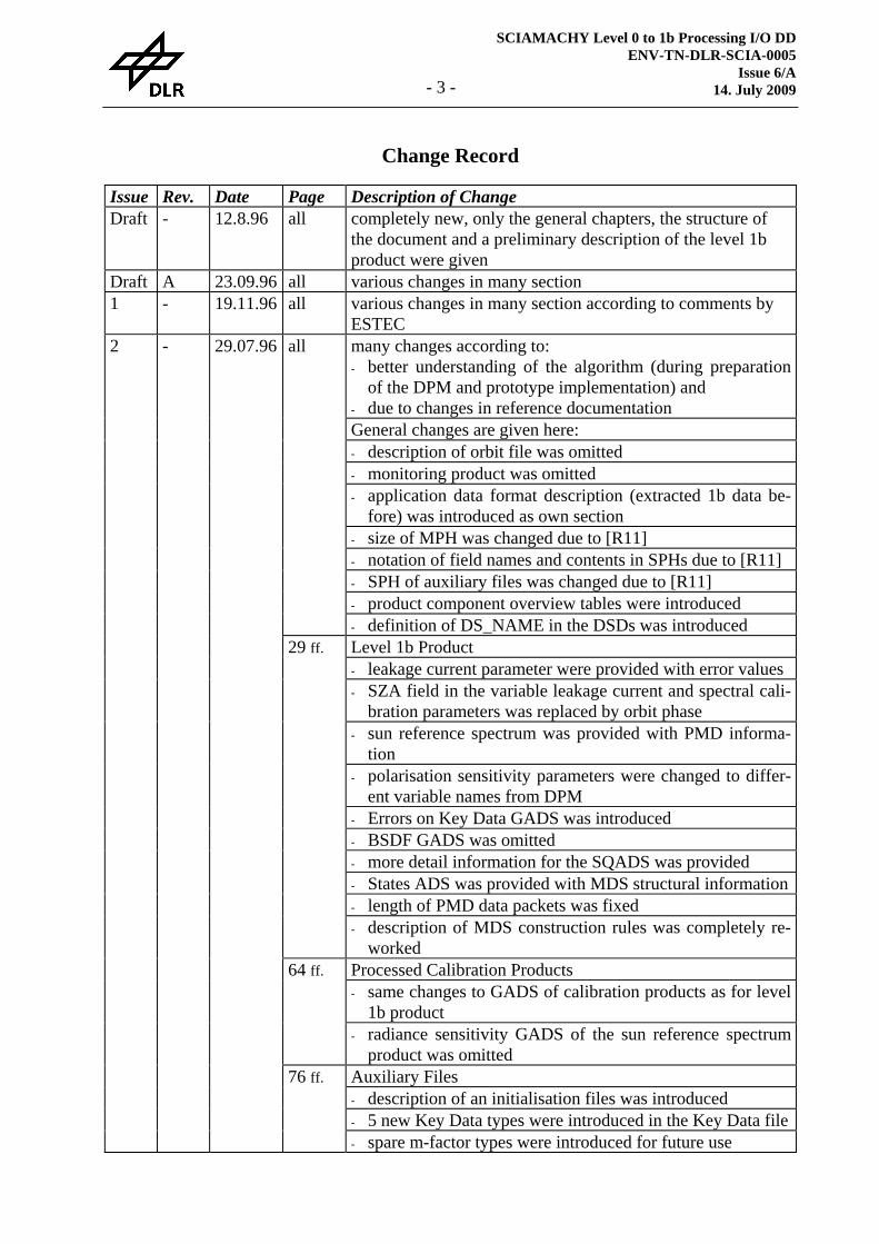
Change Record
Issue Rev. Date Page Description of Change Draft - 12.8.96 all completely new, only the general chapters, the structure of
the document and a preliminary description of the level 1b product were given
Draft A 23.09.96 all various changes in many section 1 - 19.11.96 all various changes in many section according to comments by
ESTEC many changes according to: - better understanding of the algorithm (during preparation
of the DPM and prototype implementation) and - due to changes in reference documentation General changes are given here: - description of orbit file was omitted - monitoring product was omitted - application data format description (extracted 1b data be-
fore) was introduced as own section - size of MPH was changed due to [R11] - notation of field names and contents in SPHs due to [R11] - SPH of auxiliary files was changed due to [R11] - product component overview tables were introduced
all
- definition of DS_NAME in the DSDs was introduced Level 1b Product - leakage current parameter were provided with error values - SZA field in the variable leakage current and spectral cali-
bration parameters was replaced by orbit phase - sun reference spectrum was provided with PMD informa-
tion - polarisation sensitivity parameters were changed to differ-
ent variable names from DPM - Errors on Key Data GADS was introduced - BSDF GADS was omitted - more detail information for the SQADS was provided - States ADS was provided with MDS structural information- length of PMD data packets was fixed
29 ff.
- description of MDS construction rules was completely re-worked
Processed Calibration Products - same changes to GADS of calibration products as for level
1b product
64 ff.
- radiance sensitivity GADS of the sun reference spectrum product was omitted
Auxiliary Files - description of an initialisation files was introduced - 5 new Key Data types were introduced in the Key Data file
2 - 29.07.96
76 ff.
- spare m-factor types were introduced for future use
SCIAMACHY Level 0 to 1b Processing I/O DD ENV-TN-DLR-SCIA-0005 Issue 7 14. July 2009 - 4 -
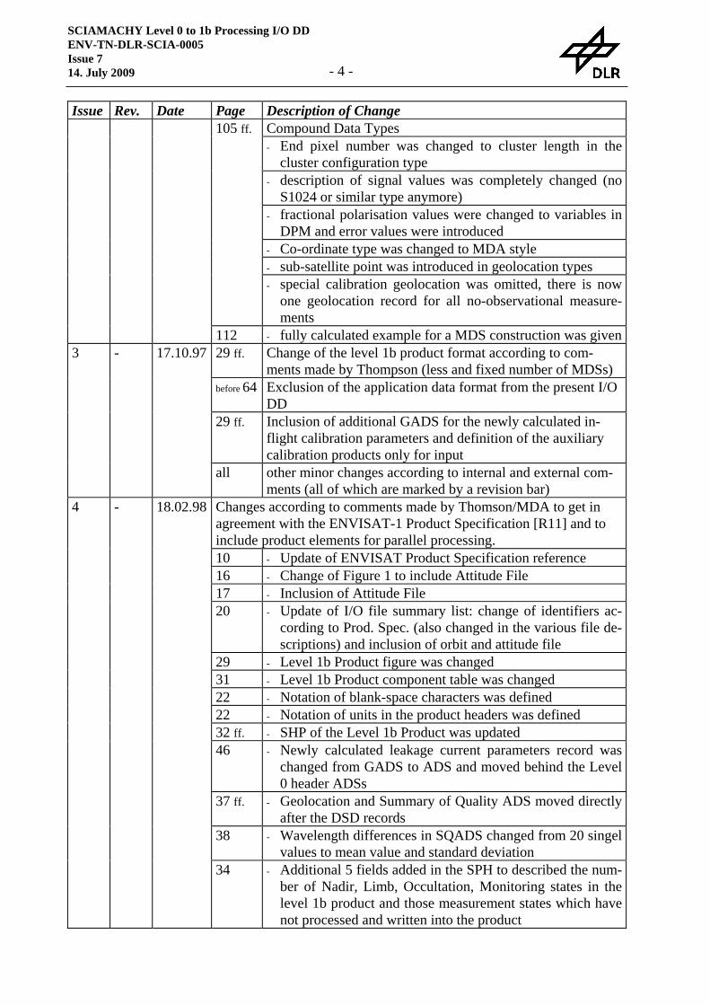
Issue Rev. Date Page Description of Change Compound Data Types - End pixel number was changed to cluster length in the
cluster configuration type - description of signal values was completely changed (no
S1024 or similar type anymore) - fractional polarisation values were changed to variables in
DPM and error values were introduced - Co-ordinate type was changed to MDA style - sub-satellite point was introduced in geolocation types
105 ff.
- special calibration geolocation was omitted, there is now one geolocation record for all no-observational measure-ments
112 - fully calculated example for a MDS construction was given29 ff. Change of the level 1b product format according to com-
ments made by Thompson (less and fixed number of MDSs) before 64 Exclusion of the application data format from the present I/O
DD 29 ff. Inclusion of additional GADS for the newly calculated in-
flight calibration parameters and definition of the auxiliary calibration products only for input
3 - 17.10.97
all other minor changes according to internal and external com-ments (all of which are marked by a revision bar)
Changes according to comments made by Thomson/MDA to get in agreement with the ENVISAT-1 Product Specification [R11] and to include product elements for parallel processing. 10 - Update of ENVISAT Product Specification reference 16 - Change of Figure 1 to include Attitude File 17 - Inclusion of Attitude File 20 - Update of I/O file summary list: change of identifiers ac-
cording to Prod. Spec. (also changed in the various file de-scriptions) and inclusion of orbit and attitude file
29 - Level 1b Product figure was changed 31 - Level 1b Product component table was changed 22 - Notation of blank-space characters was defined 22 - Notation of units in the product headers was defined 32 ff. - SHP of the Level 1b Product was updated 46 - Newly calculated leakage current parameters record was
changed from GADS to ADS and moved behind the Level 0 header ADSs
37 ff. - Geolocation and Summary of Quality ADS moved directly after the DSD records
38 - Wavelength differences in SQADS changed from 20 singel values to mean value and standard deviation
4 - 18.02.98
34 - Additional 5 fields added in the SPH to described the num-ber of Nadir, Limb, Occultation, Monitoring states in the level 1b product and those measurement states which have not processed and written into the product
SCIAMACHY Level 0 to 1b Processing I/O DD ENV-TN-DLR-SCIA-0005
Issue 6/A 14. July 2009 - 5 -
Issue Rev. Date Page Description of Change 44 - Reason code for the attachment flag was added in the
States ADS 44 - Relative offset field in the States ADS was omitted 51, 53 - Type of the Quality indicator in the MDSR was changed
from 'sl' to 'sc' 71 - Initialisation File, External State Parameters, State number,
number of elements was corrected from 2 to 1 84, 85 - Dimension KeyData parameter 25. and 26. have been re-
duced from '2' to '1' 22, 95 - Notation of geographical co-ordinates was changed from
ISO 6703 to ISO 6709 52 - Monitoring example added for the MDSR construction,
including fully calculated table 17 - Comment about in-flight calibration parameter files in the
'Processing Overview' section was updated 46, 47 - New ADSs for PPG/Etalon parameters, spectral calibration
parameters and the sun reference spectrum have been added
Additional changes: 38 - In SQADS the rainbow flag was added and the number of
spare flags was reduced to 10 41, 47, 67
- The average mirror positions were added to the sun refer-ence GADSs (level 1b product and auxiliary file) and ADS (level 1b product)
18, 42, 68, 71
- Fixed grid for the polarisation and radiance sensitivity GADSs were introduced
48, 51 - The quality flags in the level 1b product MDSR were changed to saturation and sun glint / rainbow flags and re-duced in size
48, 49, 51
- The frequency of the integrated PMDs was increased to 32 Hz due to H/W change
49, 51, 94
- The fractional polarisation values were changed to include also the U parameter for the overlapping regions
71 - A processing category indicator was introduced the exter-nal parameter component of the initialisation file
82 - The straylight parameter of the Key Data file was changed to have 4 dimensions
83, 86 - A remark about unused Key Data parameters was added 89 - 91 - The m-factor parameters were put on a wavelength grid 46 - Mean noise record was added to the newly calculated leak-
age current parameter ADS 38 - Mean difference of leakage current per channel was also
given for the PMDs 40, 46, 60
- Bad pixel mask was added to the PPG/Etalon parameters
4 A 18.03.98
61 - Data volume of PPG/Etalon auxiliary file was changed
SCIAMACHY Level 0 to 1b Processing I/O DD ENV-TN-DLR-SCIA-0005 Issue 7 14. July 2009 - 6 -
Issue Rev. Date Page Description of Change 47 - Comment about wavelength error was added to the newly
calculated spectral calibration parameters 71 - A state set-up integration time was added to the external
state parameters (spare was reduced) 86 - Data volume of Key Data file was changed 91 - Data volume of m-factor file was changed 10 - Update of reference documents (CFI and PGICD) 35 - 37 - Clear ordering of the level 1b product DS_NAMES was
added 70 - DS_NAMES for the initialisation file was added 88 ff. - Clear ordering of the m-factor DS_NAMES was added 83 - Blocking shift parameter for the SLS spectral lines added
in the Key Data file 85 - Contamination shift parameter for the Fraunhofer lines
added in the Key Data file 44 - Indices to the variable fraction of the leakage current and
the spectral calibration parameters were replaced by an or-bit phase of the state
17 - Attitude file format is now available 20 - Identifier of initialisation file fixed 23 - ISO identifier for geographical co-ordinates fixed
4 B 27.03.98
42 - Missing remark about radiance sensitivity added 22 - The unit BU⋅s was added 23 - Combined data structure concerning GeoCal was fixed 37 - The name of the spare DSD record was deleted 37 - The SQADS component was corrected (field 6); comment
about the meaning of the flags was added 38 - The meaning of the LADS component was explained for
measurement states other than nadir 44 - The States ADS was updated 49 - Formulae for product size calculation were updated for
other measurements than nadir, Lhead value was fixed 69 - Identifier for initialisation file was fixed 72 - Update for variable nature of the grids 85 - Memory effect is different for the channels, was fixed 94 - Cluster data type field added
4 C 27.08.98
97 - Combined data structure L0Hdr described 5 21.07.00 page page numbers refer to issue 4/C 40 - Addition of a precise wavelength array as a spectral GADS 40 - Modification of PPG/Etalon GADS 46 - Modification of PPG/Etalon ADS 41 - Modification of Sun Mean Reference GADS 47 - Modification of Sun Mean Reference ADS 38 - Addition of the Static Instrument Parameter GADS 95 - Modification of PolV compound data type (addition of
GDF parameters
SCIAMACHY Level 0 to 1b Processing I/O DD ENV-TN-DLR-SCIA-0005
Issue 6/A 14. July 2009 - 7 -
Issue Rev. Date Page Description of Change 37 - Modification of SQADS (addition of SAA region and hot
pixel flag) 96 - Addition of Doppler shift in Limb geolocation compound
data type 44 - Moving of straylight scaling factor from State ADS to
MDS 71 - Spectral template WLS now on keydata file, new PPG_0
template added 72 - Measurement category added to the division of states into
the various MDSs, please note moon scanning has been moved to the monitoring MDS
46 - Addition of the Average Dark Measurement ADS 46 - Moved solar straylight quantities from Leakage ADS to
Average Dark Measurement ADS 52,54 - Inserted Red Grass flag in MDS records 41,42 - Modified/new Polarisation Sensitivity and Radiance Sensi-
tivity GADS 43 - New Slit Function and Small Aperture Slit Function GADS 94 - Compound data types ESig and ESigc for Epitaxx detector
signals now equal to Reticon detector types RSig, RSigc. 56ff - Modified Calibration files according to new GADS's 69ff - Added Processing Categories GADS, new content of field
4 in Spectrum Templates GADS 74ff - Updated Parameters on Keydata file 88ff - Addition of new monitoring factor for ND filter 6 06.09.05 page page numbers refer to issue 5 11, 18,
21 - Reference to attitude (AOCS) file
34 - SPH field 11: init file version & decontamination flag 43 - More precise definition of orbit phase 45,55 - Units on the SMR (G)ADS 45,55 - New Identifiers on the SMR (G)ADS 55 - Uncalibrated solar ADS 73 - Sun reference file has one GADS (corrected description) 78 - Size of Static Parameter GADS increased to 20 kB 82ff - Key data parameters updated 106 - Non-linearity in EPITAXX detector signal 6/A 04.04.06 page page numbers refer to issue 5 11 - Reference to DPM 47 - Radiance sensitiv. GADS Nadir (corrected cut/paste error) 73 - Sun reference file: replaced figure 7 14.07.09 page Page numbers refer to this issue 11, 38 - New reference to OCRs 38 - Include LIMB_MESOSPHERE in Limb MDS
SCIAMACHY Level 0 to 1b Processing I/O DD ENV-TN-DLR-SCIA-0005 Issue 7 14. July 2009 - 8 -
Table of Content
1 Introduction ....................................................................................................................... 10 1.1 Purpose and Scope ............................................................................................................ 10 1.2 Documents ........................................................................................................................ 11 1.3 Abbreviations and Acronyms ........................................................................................... 12 1.4 Document Overview ......................................................................................................... 14
2 General Assumptions ........................................................................................................ 15 2.1 Mission Scenarios, Timelines and Instrument States ....................................................... 15 2.2 Philosophy of Level 1b Product Definition ...................................................................... 16 2.3 Processing Overview ........................................................................................................ 17 2.4 Summary of I/O Files........................................................................................................ 21
3 Detailed I/O Data Formats ............................................................................................... 22 3.1 Approach for file definition .............................................................................................. 22 3.2 Products............................................................................................................................. 26
3.2.1 Level 0 Product ......................................................................................................... 26 3.2.2 Level 1b Product ....................................................................................................... 29
3.3 Processed Calibration Files............................................................................................... 65 3.3.1 Leakage Current Parameters ..................................................................................... 65 3.3.2 PPG/Etalon Parameters ............................................................................................. 68 3.3.3 Spectral Calibration Parameters................................................................................ 71 3.3.4 Sun Reference Spectrum........................................................................................... 74
3.4 Auxiliary Data Files .......................................................................................................... 77 3.4.1 Initialisation File ....................................................................................................... 77 3.4.2 Key Data Files........................................................................................................... 82 3.4.3 m-Factor File............................................................................................................. 98
4 Generic Data Representations........................................................................................ 104 4.1 Basic Data Types ............................................................................................................ 104 4.2 Compound Data Types.................................................................................................... 105
5 Reference Timeline and State Example......................................................................... 110

SCIAMACHY Level 0 to 1b Processing I/O DD ENV-TN-DLR-SCIA-0005
Issue 6/A 14. July 2009 - 9 -
List of Figures
Figure 1: SCIAMACHY Level 0 to 1b Processing Overview...................................................... 17 Figure 2: Level 0 Data Source Packet Types ................................................................................ 26 Figure 3: Schematic Structure of the Level 1b Product ................................................................ 30 Figure 5: Schematic Structure of the Leakage Current Parameters .............................................. 65 Figure 6: Schematic Structure of the PPG/Etalon Parameters ...................................................... 68 Figure 7: Schematic Structure of the Spectral Calibration Parameters......................................... 71 Figure 8: Schematic Structure of the Sun Reference Spectrum File............................................. 74
SCIAMACHY Level 0 to 1b Processing I/O DD ENV-TN-DLR-SCIA-0005 Issue 7 14. July 2009 - 10 -
1 Introduction
1.1 Purpose and Scope
SCIAMACHY is a joint project of Germany, The Netherlands and Belgium for atmospheric measurements. SCIAMACHY has been selected by the European Space Agency (ESA) for in-clusion in the list of instruments for Earth observation research for the ENVISAT-1 polar plat-form, to be launched in 1999. The SCIAMACHY programme is currently in progress under the supervision of the SCIAMACHY science team (SSAG), headed by the Principal Investigators Professor J. P. Burrows (University of Bremen, Germany), Dr. A. Goede (SRON, The Nether-lands) and Dr. C. Muller (BISA, Belgium).
The German Remote Sensing Data Centre (DFD) plays a major role in the design, implementa-tion and operation of the SCIAMACHY ground processors (SGPs) which are part of the ENVI-SAT payload data segment (PDS), as described in [A1]. The present document is part of the technical documentation provided by DFD for the specification of the algorithm for the near real-time (NRT) SCIAMACHY ground processors in specific for the level 0 to 1b processing (SGP_01). The statement of work (SoW) [A2] was formulated by ESTEC and is the main appli-cable technical input for the present project.
The present document provides a complete list of input/output data as required or generated by the processor. In particular detailed formats for the ancillary input data (especially instrument characterisation data), all types of calibration data and possible external data is given.
SCIAMACHY Level 0 to 1b Processing I/O DD ENV-TN-DLR-SCIA-0005
Issue 6/A 14. July 2009 - 11 -
1.2 Documents
Following documents are applicable for this technical note:
[A1] ENVISAT-1 Ground Segment Concept, ESA/PB-EO(94)75, Issue 5, 20 September 1994
[A2] Algorithm Definition and Software Prototyping for SCIAMACHY Ground Processing up to Level 2, PO-SW-ESA-GS-0294, Issue 2, 8.9.95
[A3] ESA Software Engineering Standards, ESA PSS-05-0, Issue 2, Feb. 1991 The standards defined in this document are tailored by Appendix 3 of [A2]
The following documents are referenced:
[R1] SCIAMACHY Instrument Requirements Document, PO-RS-DAR-EP-0001, Issue 3 Rev. 1, 12.12.95
[R2] SCIAMACHY Operations Concept: I. Mission Scenarios, PO-TN-DLR-SH-0001/1, Is-sue 2, Rev. 0, 31.5.96
[R3] SCIAMACHY Operations Concept: II. Timeline Generation Rules and Reference Time-lines, PO-TN-DLR-SH-0001/2, Issue 1, Rev. 0, 31.10.95
[R4] SCIAMACHY Operations Concept: III. Instrument States, PO-TN-DLR-SH-0001/3, Issue 2, Rev. 0, 25.7.96 (plus Annex from 29.10.96)
[R5] Guidelines for the Specification of Ground Processing Algorithms, PO-RS-ESA-GS-0252, Issue 1, 23.3.95
[R6] ENVISAT-1 Product Format Guidelines, PO-TN-ESA-GS-0242, Issue 5.0, 10.11.95
[R7] ENVISAT-1 Product Definition Guidelines, PO-TN-ESA-GS-0231
[R8] ENVISAT-1 Product Processing Guidelines, PO-TN-ESA-GS-0347, Issue 1.2, 8.5.96
[R9] Definition of Instrument Characterisation Data Base, PO-ID-DOR-SY-0037, Issue 1, 11.5.94
[R10] SCIAMACHY Calibration Plan, PL-SCIA-1000TP/022, Issue 2, 22.1.96
[R11] ENVISAT-1 Products Specification, PO-RS-MDA-GS-2009, Issue 3 Rev. C, 19.6.97
[R12] Payload to Ground Segment Interface Control Document, Volume 14: Measurement Data Definition and Format Description for SCIAMACHY, PO-ID-DOR-SY-0032, Issue 3, 14.1.97
[R13] SCIAMACHY Calibration Key Data, TN-SCIA-0000TP/128, Issue 0.6, 1.11.96
[R14] SCIAMACHY Product Definition, ENV-PD-DLR-SCIA-0001, Issue 1, 15.3.95
[R15] SCIAMACHY Level 0 to 1b Processing, Detailed Processing Model / Parameter Data List, ENV-TN-DLR-SCIA-0006, Issue 4/B, 09.11.2005
[R16] Re-engineering of Mission Analysis software for ENVISAT-1, PPF_POINTING soft-ware User Manual, PO-IS-DMS-GS-0559, Issue 5.4, 17.05.05
[R17] SCIAMACHY OCR Implementation, http://atmos.caf.dlr.de/projects/scops/

SCIAMACHY Level 0 to 1b Processing I/O DD ENV-TN-DLR-SCIA-0005 Issue 7 14. July 2009 - 12 -
1.3 Abbreviations and Acronyms
A list of abbreviations and acronyms which are used throughout this document is given below: ADS Annotation Data Set ADSR Annotation Data Set Record AO Announcement of Opportunity ASCII American Standard Code for Information Interchange ASM Azimuth Scan Mirror BCPS Broadcast Pulse Signal BSDF Bi-directional Scattering Distribution Function BU Binary Unit CFI Customer Furnished Items DARA Deutsche Agentur für Raumfahrtangelegenheiten DFD Deutsches Fernerkundungsdatenzentrum DLR Deutsches Zentrum für Luft- und Raumfahrt e.V. DOAS Differential Optical Absorption Spectroscopy D-PAC German Processing and Archiving Centre DS Data Set DSD Data Set Description DSR Data Set Record ENVISAT Environmental Satellite ESA European Space Agency ESM Elevation Scan Mirror ESTEC European Space Centre of Technology FOS Flight Operation Segment FPN Fixed Pattern Noise GADS Global Annotation Data Set GOME Global Ozone Monitoring Experiment HK House Keeping IECF Instrument Engineering Calibration Facility IFE Institut für Fernerkundung der Universität Bremen IFOV Instantaneous Field of View I/O DD Input/Output Data Definition ISP Instrument Science Packet LBR Low Bit Rate LC Leakage Current MB Megabyte MDS Measurement Data Set MDSR Measurement Data Set Record MPH Main Product Header N/A not applicable ND Neutral Density NRT Near Real Time PAC Processing and Archiving Centre PCA Polarisation Correction Algorithm PCD Product Confidence Data PDHS Payload Data Handling Segment PDS Payload Data Segment
SCIAMACHY Level 0 to 1b Processing I/O DD ENV-TN-DLR-SCIA-0005
Issue 6/A 14. July 2009 - 13 -
PET Pixel Exposure Time PMD Polarisation Measurement Device PMTC Power, Mechanics and Thermal Control Unit PPG Pixel-to-Pixel Gain PQF Product Quality Facility SBT Satellite Binary Time SCIAMACHY Scanning Imaging Absorption Spectrometer for Atmospheric Chartography SDPU Signal Data Processing Unit SLS Spectral Light Source SGP SCIAMACHY Ground Processor SGP_01 SCIAMACHY Ground Processor for Level 0 to 1b Processing SOS SCIAMACHY Operations Support SoW Statement of Work SPH Specific Product Header SRON Space Research Organisation of The Netherlands SSAG SCIAMACHY Scientific Advisory Group SZA Solar Zenith Angle TPD Technisch Physische Dienst UTC Universal Time Co-ordinate WLS White Light Source

SCIAMACHY Level 0 to 1b Processing I/O DD ENV-TN-DLR-SCIA-0005 Issue 7 14. July 2009 - 14 -
1.4 Document Overview
The present document is divided into the following sections:
• General Assumptions − Measurement Scenarios, Timelines and Instrument States − Philosophy of Level 1b Product Definition − Processing Overview − Summary of I/O Files
• Detailed I/O Data Formats − Approach for file definition − Products
- Level 0 Product - Level 1b Product
− Processed Calibration Files - Leakage Current Parameters - PPG/Etalon Parameters - Spectral Calibration Parameters - Sun Reference Spectrum
− Auxiliary Data Files - Initialisation File - Key Data Files - m-Factor File
• Generic Data Representations − Basic Data Types − Compound Data Types
• Reference Timeline and State Examples

SCIAMACHY Level 0 to 1b Processing I/O DD ENV-TN-DLR-SCIA-0005
Issue 6/A 14. July 2009 - 15 -
2 General Assumptions
2.1 Mission Scenarios, Timelines and Instrument States
The operation concept of SCIAMACHY is based on a hierarchy of Mission Scenarios, Timelines and States. A detailed description of the SCIAMACHY operations concept is given in [R2], [R3] and [R4].
The mission scenarios describe categories of measurements to be performed and how the various categories are related to each other. The timelines represent the implementation of the mission scenarios in the sense that they give a detailed outline of the sequence of individual measure-ments. Timelines can be generated once scientific and technical mission planning rules have been established. The states are the lowest level in the hierarchy; each state represents a single measurement type with a specific set of parameters.
The mission scenarios of SCIAMACHY depend on the time frame of the mission. Since the tar-get lifetime of ENVISAT and its payload is 5 years, it is likely that these scenarios will change. During the commissioning phase in the first 6 months of operation after launch, the sequence of measurements will differ from that in the routine operations phase. Tasks such as instrument validation and in-flight testing must be accomplished in the commissioning phase, while in the routine phase a more regular continuous operation pattern will be implemented. A high-level SCIAMACHY operations plan will be formulated to outline the overall mission goals over the complete 5 year time frame. Since seasonal variations of atmospheric parameters will dictate modifications to some of the observation settings, the scenarios will also follow a yearly pattern. Finally, with the moon being visible to SCIAMACHY for only a small fraction of its orbit around the Earth, the mission scenarios must be synchronised with the lunar cycle.
A fixed number of SCIAMACHY timelines will be stored on-board; there will be the opportu-nity for updating timelines according to established and configuration-controlled procedures. Consequently, in order to facilitate daily operations, it is required to develop timeline schemes, which cover most of the envisaged instrument activities (mission scenarios). Since the ENVI-SAT launch is still about 2.5 years in the future (at the time of writing), only initial ideas on SCIAMACHY time-lining are currently available. However, these ideas do include the scientific and technical principles to be followed when generating timelines. Thus one can generate refer-ence timelines, which can be considered as examples for the sequence of SCIAMACHY activi-ties; the final timelines for on-board storage will evolve from these reference timelines. One of these reference timelines is described in section 5, where it was used to calculate the parameters and sizes of the level 1b product, described in section 3.2.2.
The states are classified according to measurement categories depending on the type of observa-tion e.g. nadir, limb, sun occultation, spectral lamp source, etc. Level 0 to 1b processing picks up the measurements of a complete state of a certain measurement category and routes them through the various processing elements of the level 0 to 1b processor to fill a number of Meas-urement Data Sets (MDS) and Annotation Data Sets (ADS) for the different groups of measure-ment categories. The hierarchy of the SCIAMACHY operational concept above the level of these instrument states is (in principle) invisible to a level 1b data user.
SCIAMACHY Level 0 to 1b Processing I/O DD ENV-TN-DLR-SCIA-0005 Issue 7 14. July 2009 - 16 -
2.2 Philosophy of Level 1b Product Definition
The following requirements are driving factors for the design of the level 1b product format, as they have been for the design of the GOME level 1 product:
• Storage space should be saved in the archive and on distribution media
• Most of the information included in the level 0 data should be retained in the level 1b product
• Error values should be given for the earth-shine spectrum and the sun reference spectrum in terms of a relative pixel-to-pixel or noise error and an absolute error on the calibrated radi-ance
There are basically two options available to fulfil these requirements: full application of all cali-bration parameters or no application of any parameters. The first option requires the following record for each detector pixel read-out: the radiance, the noise error and the absolute error on the radiance given as floats and a flag given as unsigned character. This yields a size of 13 Bytes per detector pixel and measurement. This approach still requires an application programme, because the wavelength has to be calculated from the corresponding coefficients. Otherwise the size of the record including wavelength would be 17 Bytes. The second option just requires the binary signal read-out (24 bit as a maximum, 16 bits for clusters which are not co-added), an unsigned character (8 bit) for the correction of the memory effect (RETICON arrays only) and an un-signed character for the straylight (8 bit). This yields 3, 4 or 5 Bytes depending on detector mate-rial and co-adding. This means that level 1b products using the full application of all calibration parameters require between 3 or 4 times more space on storage and distribution media than products which require the use of an application programme.
It may also be note that most of the potential users of level 1b data are developers of new re-trieval algorithms. These type of users are very interested in the details of the actual level 0 to 1b processing and even want to test various approaches which require the knowledge of level 0 data (e.g. DOAS processing without application of the polarisation correction and to do the retrieval of the polarisation during level 1b to 2 processing), but this data is not available to the general SCIAMACHY data user.
These requirements imply a format where no calibration data is actually applied to the spectrum data. To get level 1b data which might be used for further (e.g. level 1b to 2) processing an addi-tional processing step must be performed to do the application of the calibration data to the sig-nal data and to calculate the associated errors.
SCIAMACHY Level 0 to 1b Processing I/O DD ENV-TN-DLR-SCIA-0005
Issue 6/A 14. July 2009 - 17 -
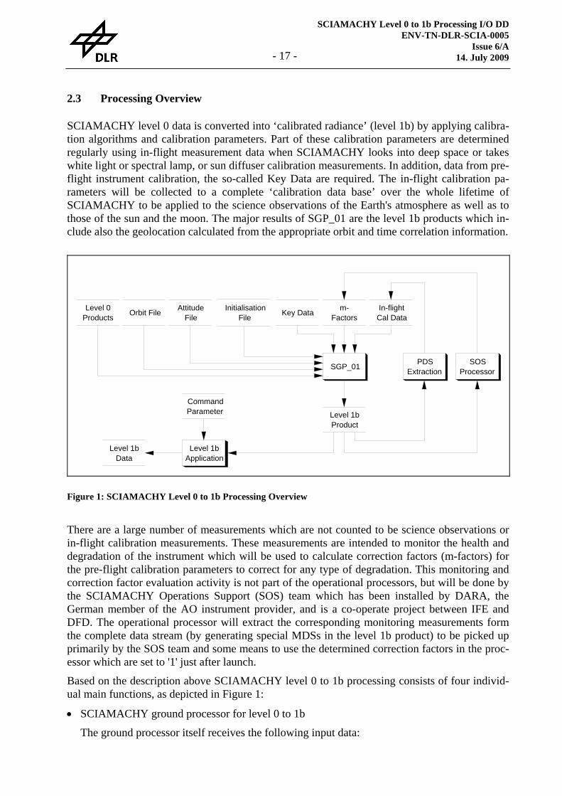
2.3 Processing Overview
SCIAMACHY level 0 data is converted into ‘calibrated radiance’ (level 1b) by applying calibra-tion algorithms and calibration parameters. Part of these calibration parameters are determined regularly using in-flight measurement data when SCIAMACHY looks into deep space or takes white light or spectral lamp, or sun diffuser calibration measurements. In addition, data from pre-flight instrument calibration, the so-called Key Data are required. The in-flight calibration pa-rameters will be collected to a complete ‘calibration data base’ over the whole lifetime of SCIAMACHY to be applied to the science observations of the Earth's atmosphere as well as to those of the sun and the moon. The major results of SGP_01 are the level 1b products which in-clude also the geolocation calculated from the appropriate orbit and time correlation information.
There are a large number of measurements which are not counted to be science observations or in-flight calibration measurements. These measurements are intended to monitor the health and degradation of the instrument which will be used to calculate correction factors (m-factors) for the pre-flight calibration parameters to correct for any type of degradation. This monitoring and correction factor evaluation activity is not part of the operational processors, but will be done by the SCIAMACHY Operations Support (SOS) team which has been installed by DARA, the German member of the AO instrument provider, and is a co-operate project between IFE and DFD. The operational processor will extract the corresponding monitoring measurements form the complete data stream (by generating special MDSs in the level 1b product) to be picked up primarily by the SOS team and some means to use the determined correction factors in the proc-essor which are set to '1' just after launch.
Based on the description above SCIAMACHY level 0 to 1b processing consists of four individ-ual main functions, as depicted in Figure 1:
• SCIAMACHY ground processor for level 0 to 1b
The ground processor itself receives the following input data:
Level 0Products
InitialisationFile Key Data m-
FactorsIn-flightCal Data
SGP_01
Level 1bProduct
AttitudeFile
SOSProcessor
Level 1bApplication
Level 1bData
PDSExtraction
CommandParameter
Orbit File
Figure 1: SCIAMACHY Level 0 to 1b Processing Overview
SCIAMACHY Level 0 to 1b Processing I/O DD ENV-TN-DLR-SCIA-0005 Issue 7 14. July 2009 - 18 -
− SCIAMACHY level 0 products There is just one level 0 product on input. Depending on the consolidation status of this level 0 product the consolidation status of the resulting level 1b product will be accord-ingly.
− Orbit files For NRT processing the predicted state vector in the MPH of the level 0 product has to be applied for the geolocation of the measurements, because no better orbital information is available by that time. During off-line processing the different orbit products are available and will be provided by the processing environment. Whenever orbit files are available, they shall be used instead of the predicted state vector in the level 0 product.
It is not required to describe the format of orbit files in the present I/O DD. On one hand these files are described somewhere else in the PDS documentation and on the other hand they are not explicitly read by SGP_01, but the CFI orbit propagation routines which re-quire just the filename of these files.
− Attitude File This file is assumed to be available for each orbit and contains the AOCS parameters and information about the attitude of the ENVISAT-1 spacecraft (roll, pitch and yaw). If this file is available to SGP_01 the information therein shall be extracted and provided as AOCS parameters, mis-pointing angles and rate to the target calculation of the geolocation module. If the file is not available, the AOCS parameters need to be calculated and the mis-pointing information has to be set to zero.
It is not required to describe the format of attitude file in the present I/O DD, because it is handled automatically by the orbit propagation CFI [R16].
− A Key Data file The Key Data comprises the complete set of pre-flight calibration data which is provided by the instrument provider (TPD), in particular the following information is included:
- Bi-directional scattering distribution function of the sun diffuser - Straylight characteristics - Polarisation sensitivity parameters - Radiance sensitivity parameters - Errors on all Key Data
− An m-factor file Due to the degradation of the instrument during its stay in orbit the pre-flight calibration data would have to be changed. Instead of actually changing the pre-flight data the calibra-tion plan [R10] foresees the usage of correction factors, the so-called m-factors, which are collected in this file. See the description of the SOS processor below.
− In-flight Calibration Data files For the operation of SGP_01 this type of auxiliary products is essential. In general the in-flight calibration data is determined during operation of the processor, but only if the cor-responding calibration measurements are included in the set of level 0 data to be proc-essed. These newly calculated in-flight calibration parameters are stored in a special set of ADSs from which they are picked up by PDS and/or IECF and used for the generation of new auxiliary products, as described in section 3.3 on page 65. For the current processing the ‘historic’ in-flight calibration data from the auxiliary product files on input are used. The following parameters are included in these files (one file for each parameter type):
SCIAMACHY Level 0 to 1b Processing I/O DD ENV-TN-DLR-SCIA-0005
Issue 6/A 14. July 2009 - 19 -
- Leakage Current Parameters - Pixel-to-pixel gain and Etalon Parameters - Spectral Calibration Parameters - Sun Reference Spectrum
− An initialisation file This file includes a large number of parameters which control nearly every module of SGP_01. Usage of such an initialisation file increases the maintainability of the processor, as these parameters may also be included as constants directly into the code. Some very important elements of this files are the following:
- Templates of solar and/or earth-shine spectra used for providing spectral calibration offsets
- Table of set-up time and configuration per state - Polarisation and Radiance Sensitivity Grids
The SGP_01 processor generates the following output: − Level 1b product − Each run of SGP_01 generates just one level 1b product. Depending on the consolidation
status of the level 0 product on input (consolidated or unconsolidated) the generated prod-uct has the corresponding type. Whenever in-flight calibration measurements were present in the level 0 data new in-flight calibration parameters will have been processed. This new calibration data has to be inserted into the level 1b product to be extracted by PDS for sub-sequent runs of SGP_01.
• Level 1b application programme
The level 1b application programme requires the following input data: − Level 1b product; the level 1b data product is in principle the only source of data to gener-
ate level 1b data. All pieces of information which are required to do the application of cali-bration parameters and the calculation of the associated errors is available in this product.
− Command parameters; the application programme is able to extract the complete set of in-formation which is included in the level 1b product, if no command parameters are given a default application e.g. which is required for the following level 1b to 2 NRT processing is done. The command parameters may be used to tailor the application as follows: - display general product information (no data extracted) - display state information only (no data extracted) - display geolocation information only (no data extracted) - extract calibration data only (no data extracted) - extract a certain type of states only (e.g. only nadir states for NRT processing) - extract selected clusters or wavelength regions only - extract ground scenes of a certain period (in terms number of scene or time frame) - apply only selected calibration parameters only
The level 1b application programme generates the following output: − Level 1b application data
depending on the command parameters, as described before, the level 1b application data may have a lot of various appearances useful for specific purposes.
• In-flight calibration data base
One set of level 0 data on input of a certain work order may not include all in-flight calibra-tion measurements which are required for the processing. Therefore, ‘historic’ in-flight cali-

SCIAMACHY Level 0 to 1b Processing I/O DD ENV-TN-DLR-SCIA-0005 Issue 7 14. July 2009 - 20 -
bration parameters calculate during former work orders have to be applied and collected into a ‘calibration data base’ to be applied to the science observations.
• SOS processor
As explained before, there are some measurements which will monitor the health and degra-dation of the instrument and eventually will be used to calculate correction factors (m-factors) for the pre-flight calibration parameters to correct for any type of degradation. This monitor-ing and correction factor evaluation activity is not part of the operational processors, but will be done by the SCIAMACHY Operations Support (SOS) team. The operational processor will produce special MDSs in the level 1b products which contain the corresponding monitor-ing measurements. These special MDSs may be used by the SOS team for the generation of the correction factors.
SCIAMACHY Level 0 to 1b Processing I/O DD ENV-TN-DLR-SCIA-0005
Issue 6/A 14. July 2009 - 21 -
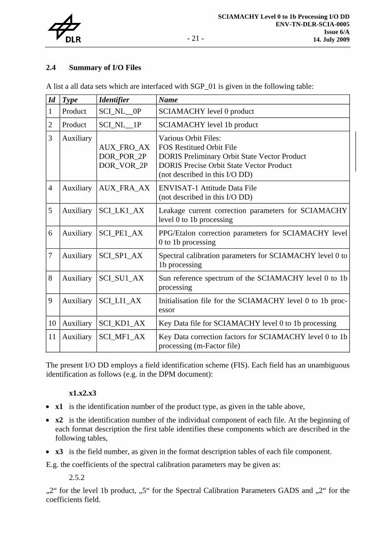
2.4 Summary of I/O Files
A list a all data sets which are interfaced with SGP_01 is given in the following table:
Id Type Identifier Name 1 Product SCI_NL__0P SCIAMACHY level 0 product
2 Product SCI_NL__1P SCIAMACHY level 1b product
3 Auxiliary AUX_FRO_AX DOR_POR_2P DOR_VOR_2P
Various Orbit Files: FOS Restitued Orbit File DORIS Preliminary Orbit State Vector Product DORIS Precise Orbit State Vector Product (not described in this I/O DD)
4 Auxiliary AUX_FRA_AX ENVISAT-1 Attitude Data File (not described in this I/O DD)
5 Auxiliary SCI_LK1_AX Leakage current correction parameters for SCIAMACHY level 0 to 1b processing
6 Auxiliary SCI_PE1_AX PPG/Etalon correction parameters for SCIAMACHY level 0 to 1b processing
7 Auxiliary SCI_SP1_AX Spectral calibration parameters for SCIAMACHY level 0 to 1b processing
8 Auxiliary SCI_SU1_AX Sun reference spectrum of the SCIAMACHY level 0 to 1b processing
9 Auxiliary SCI_LI1_AX Initialisation file for the SCIAMACHY level 0 to 1b proc-essor
10 Auxiliary SCI_KD1_AX Key Data file for SCIAMACHY level 0 to 1b processing
11 Auxiliary SCI_MF1_AX Key Data correction factors for SCIAMACHY level 0 to 1b processing (m-Factor file)
The present I/O DD employs a field identification scheme (FIS). Each field has an unambiguous identification as follows (e.g. in the DPM document):
x1.x2.x3
• x1 is the identification number of the product type, as given in the table above,
• x2 is the identification number of the individual component of each file. At the beginning of each format description the first table identifies these components which are described in the following tables,
• x3 is the field number, as given in the format description tables of each file component.
E.g. the coefficients of the spectral calibration parameters may be given as:
2.5.2
„2“ for the level 1b product, „5“ for the Spectral Calibration Parameters GADS and „2“ for the coefficients field.
SCIAMACHY Level 0 to 1b Processing I/O DD ENV-TN-DLR-SCIA-0005 Issue 7 14. July 2009 - 22 -
3 Detailed I/O Data Formats
3.1 Approach for file definition
For each file described in this document, the information is provided following a standardised template. The file description is broken down into the following categories: identifier, name, type, description, format, sizing, data volume, throughput and remarks. In this section each cate-gory is defined and the different descriptors used within the categories are presented.
Identifier
An identifier has been defined for each kind of file used and/or generated at the ground segment. This identifier will be used for referring to specific kind of files and for referring to the associ-ated file format. The identifiers are listed in the summary table of the previous section.
Name
This section contains a short descriptive name of the file.
Type
The file type defines the general relation of the file with the ground processor. The following types are defined: Input: The file contains additional data coming from the FOS or other ESA entities.
This type is not present in the present specification. Product: The file is either the primary data coming from the Space Segment or an output
of a ground processor, to be delivered to the end users. Auxiliary: The file is an input to the ground processor containing data coming neither
from the space segment nor from the ground processor. Data of this type may originate from on-ground characterisation or may be determined analytically. For the generic environment these type of files are handled also like products.
There is a special type of auxiliary file which is an intermediate input/output of the ground processor. It is the result of the processing of special calibration measurements. This file is used by the ground processor for further processing towards the generation of user products. For the generic environment these type of files are handled like products.
Besides this general classification it is noted in Italic whether the file is used as input, output or both at the interface of the processor.
Description
This section provides details about the contents and purpose of the file.
Format
The level 0 product file is composed of source packets. The format of source packets was de-fined by the instrument provider. The format of the level 1b product and all other files in this specification have been defined according to the guidelines of [R6] and the approach described in the following paragraphs:
SCIAMACHY Level 0 to 1b Processing I/O DD ENV-TN-DLR-SCIA-0005
Issue 6/A 14. July 2009 - 23 -
• A file is divided into four main parts: a general header (MPH), a specific header (SPH), data set descriptors (DSD) followed by specific data sets (DS) of the corresponding input/output file. Each of these parts has a specific structure defined in the following sections.
• The detailed format is given in form of tables containing a field number, comment, unit, data type, number of elements (#) and size column.
• Note that in the data definitions in the present document, the notation '∅' is used to indicate the inclusion of an ASCII blank-space character.
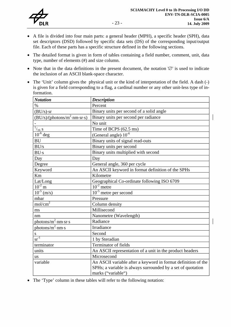
• The ‘Unit’ column gives the physical unit or the kind of interpretation of the field. A dash (-) is given for a field corresponding to a flag, a cardinal number or any other unit-less type of in-formation. Notation Description % Percent (BU/s)⋅sr Binary units per second of a solid angle (BU/s)/(photons/m2⋅nm⋅sr⋅s) Binary units per second per radiance - No unit 1/16 s Time of BCPS (62.5 ms) 10-6 deg (General angle)⋅10-6 BU Binary units of signal read-outs BU/s Binary units per second BU⋅s Binary units multiplied with second Day Day Degree General angle, 360 per cycle Keyword An ASCII keyword in format definition of the SPHs Km Kilometre Lat/Long Geographical Co-ordinate following ISO 6709 10-2 m 10-2 metre 10-5 (m/s) 10-5 metre per second mbar Pressure mol/cm2 Column density ms Millisecond nm Nanometre (Wavelength) photons/m2⋅nm⋅sr⋅s Radiance photons/m2⋅nm⋅s Irradiance s Second sr-1 1 by Steradian terminator Terminator of fields units An ASCII representation of a unit in the product headers us Microsecond variable An ASCII variable after a keyword in format definition of the
SPHs; a variable is always surrounded by a set of quotation marks (“variable“)
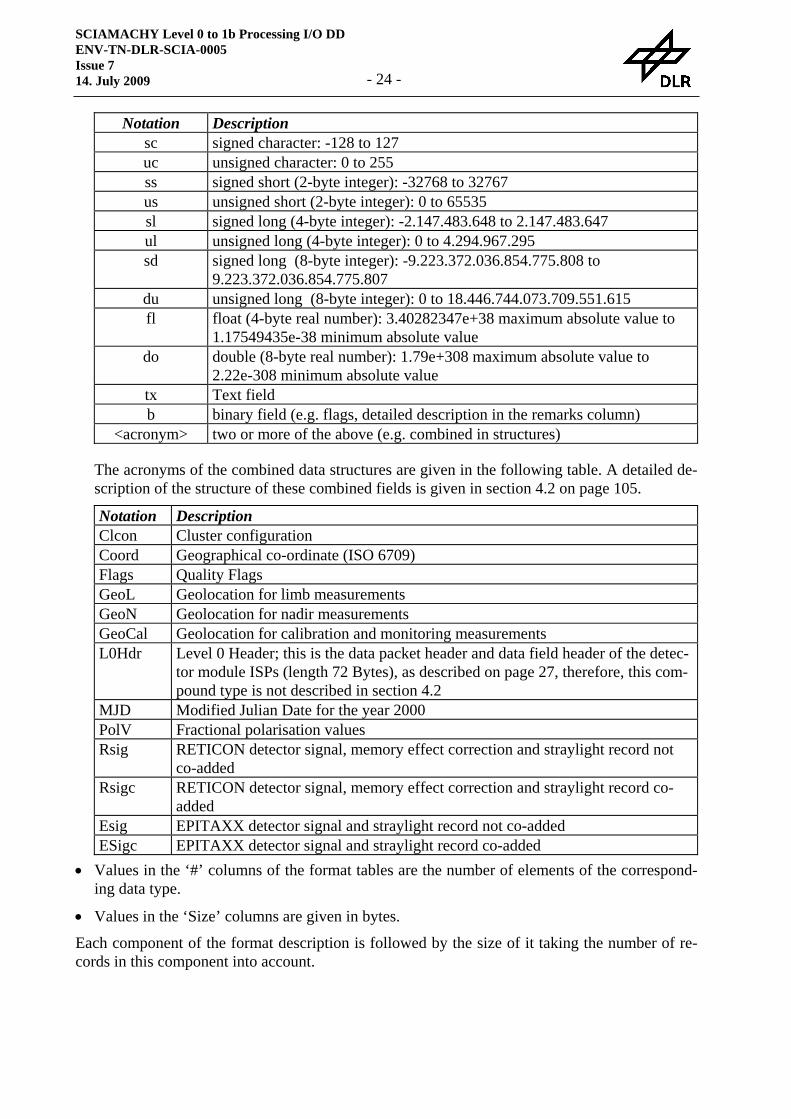
• The ‘Type’ column in these tables will refer to the following notation:
SCIAMACHY Level 0 to 1b Processing I/O DD ENV-TN-DLR-SCIA-0005 Issue 7 14. July 2009 - 24 -
Notation Description sc signed character: -128 to 127 uc unsigned character: 0 to 255 ss signed short (2-byte integer): -32768 to 32767 us unsigned short (2-byte integer): 0 to 65535 sl signed long (4-byte integer): -2.147.483.648 to 2.147.483.647 ul unsigned long (4-byte integer): 0 to 4.294.967.295 sd signed long (8-byte integer): -9.223.372.036.854.775.808 to
9.223.372.036.854.775.807 du unsigned long (8-byte integer): 0 to 18.446.744.073.709.551.615 fl float (4-byte real number): 3.40282347e+38 maximum absolute value to
1.17549435e-38 minimum absolute value do double (8-byte real number): 1.79e+308 maximum absolute value to
2.22e-308 minimum absolute value tx Text field b binary field (e.g. flags, detailed description in the remarks column)
<acronym> two or more of the above (e.g. combined in structures)
The acronyms of the combined data structures are given in the following table. A detailed de-scription of the structure of these combined fields is given in section 4.2 on page 105.
Notation Description Clcon Cluster configuration Coord Geographical co-ordinate (ISO 6709) Flags Quality Flags GeoL Geolocation for limb measurements GeoN Geolocation for nadir measurements GeoCal Geolocation for calibration and monitoring measurements L0Hdr Level 0 Header; this is the data packet header and data field header of the detec-
tor module ISPs (length 72 Bytes), as described on page 27, therefore, this com-pound type is not described in section 4.2
MJD Modified Julian Date for the year 2000 PolV Fractional polarisation values Rsig RETICON detector signal, memory effect correction and straylight record not
co-added Rsigc RETICON detector signal, memory effect correction and straylight record co-
added Esig EPITAXX detector signal and straylight record not co-added ESigc EPITAXX detector signal and straylight record co-added
• Values in the ‘#’ columns of the format tables are the number of elements of the correspond-ing data type.
• Values in the ‘Size’ columns are given in bytes.
Each component of the format description is followed by the size of it taking the number of re-cords in this component into account.

SCIAMACHY Level 0 to 1b Processing I/O DD ENV-TN-DLR-SCIA-0005
Issue 6/A 14. July 2009 - 25 -
Sizing
The granule which makes up a certain interface file is defined.
Data Volume
The size for a typical reference data set as a whole is given.
Throughput
The number of data sets per time frame is given.
Remarks
Any remarks which are not obvious from the descriptions above are given here.
SCIAMACHY Level 0 to 1b Processing I/O DD ENV-TN-DLR-SCIA-0005 Issue 7 14. July 2009 - 26 -
3.2 Products
3.2.1 Level 0 Product
Identifier
SCI_NL__0P
Name
SCIAMACHY level 0 product
Type
Product (Input)
Description
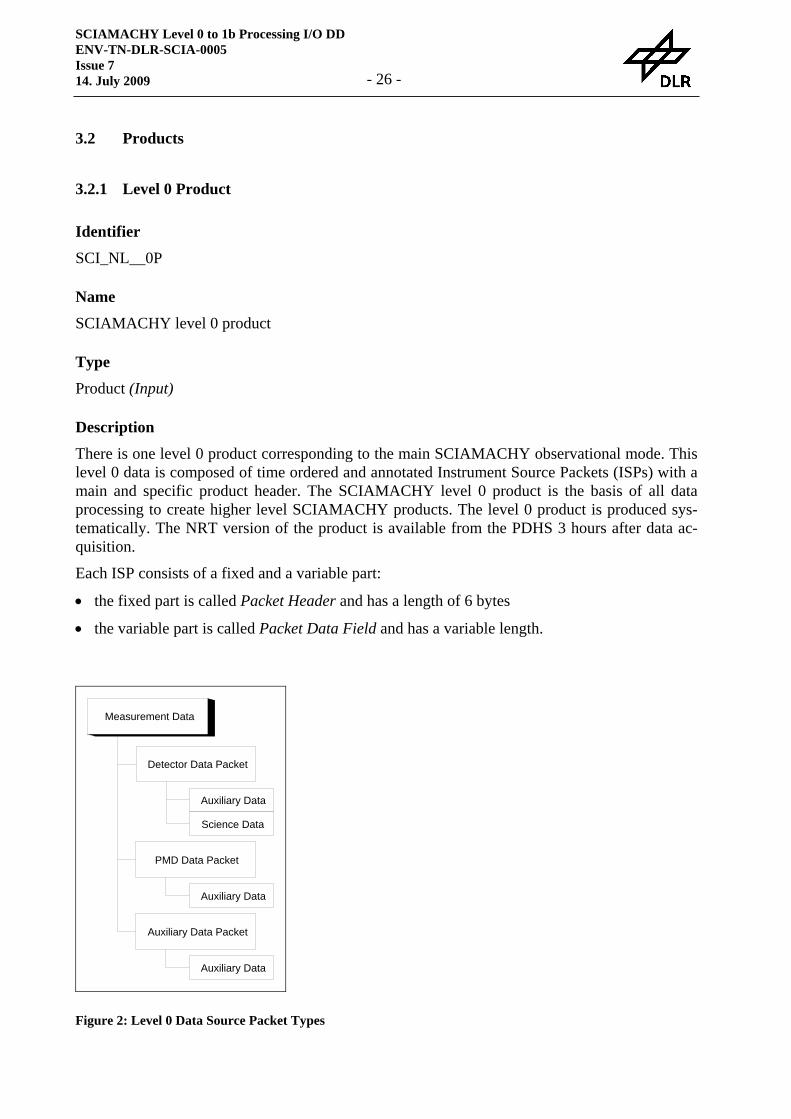
There is one level 0 product corresponding to the main SCIAMACHY observational mode. This level 0 data is composed of time ordered and annotated Instrument Source Packets (ISPs) with a main and specific product header. The SCIAMACHY level 0 product is the basis of all data processing to create higher level SCIAMACHY products. The level 0 product is produced sys-tematically. The NRT version of the product is available from the PDHS 3 hours after data ac-quisition.
Each ISP consists of a fixed and a variable part:
• the fixed part is called Packet Header and has a length of 6 bytes
• the variable part is called Packet Data Field and has a variable length.
Measurement Data
Detector Data Packet
PMD Data Packet
Auxiliary Data Packet
Auxiliary Data
Auxiliary Data
Auxiliary Data
Science Data
Figure 2: Level 0 Data Source Packet Types

SCIAMACHY Level 0 to 1b Processing I/O DD ENV-TN-DLR-SCIA-0005
Issue 6/A 14. July 2009 - 27 -
The Data Field itself is divided into:
• Data Field Header
• Source Data
The first 16 bits of the data field header contain the data field header length to identify the begin of the source data.
The SCIAMACHY instrument generates three different types of ISPs:
The packets can be distinguished by the PACKET parameter in Data Field Header.
• A Detector Data Packet consists of: − a packet header (6 Bytes) − a data field header of fixed length; this data field header has a length of 66 Bytes and will
be copied together with the packet to the MDSRs of the level 1b product − a variable number of detector channel data blocks
A channel data block consists of:
- a channel identification - a channel data header of fixed length - a variable number of pixel data blocks
A pixel data block consists of:
− a cluster identification − a counter of pixel data blocks − cluster definition (start pixel, length, co-adding factor) − pixel data of the pixels belonging to the cluster
• A PMD Data Packet consists of: − a packet header − a data field header of fixed length − 200 PMD data blocks (40 Hz readouts collected in 5 seconds)
A PMD data block consists of:
- measurement data from 7 PMDs; two values with different gain for each PMD • An Auxiliary Data Packet consists of:
− a packet header − a data field header of fixed length − 5 PMTC auxiliary data frames (collected in 5 seconds)
A PMTC auxiliary data frame consists of:
- 16 scanner position data blocks (16 Hz readouts collected in 1 second) - a temperature control HK data block

SCIAMACHY Level 0 to 1b Processing I/O DD ENV-TN-DLR-SCIA-0005 Issue 7 14. July 2009 - 28 -
Format
The detailed format of the ISPs is given in [R12]. The MPH, SPH and DSD is described in [R11].
Sizing
The sizing of a unconsolidated level 0 product is determined by the down link acquisition times which cover approximately one orbit. After level 0 consolidation processing the boundaries of a level 0 product are determined by the satellite crossing times of the ascending node. One con-solidated level 0 product covers exactly one orbit.
Data Volume
Approximately 320 MB per orbit
Throughput
SCIAMACHY is intended for continuous measuring. This implies approximately 14.3 orbits and level 0 products per day.
Remarks
N/A
SCIAMACHY Level 0 to 1b Processing I/O DD ENV-TN-DLR-SCIA-0005
Issue 6/A 14. July 2009 - 29 -
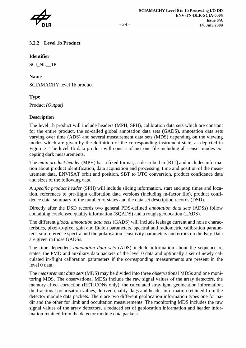
3.2.2 Level 1b Product
Identifier
SCI_NL__1P
Name
SCIAMACHY level 1b product
Type
Product (Output)
Description
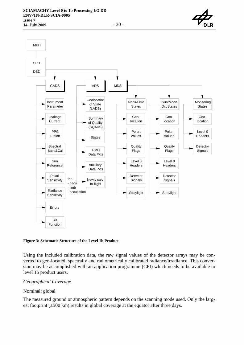
The level 1b product will include headers (MPH, SPH), calibration data sets which are constant for the entire product, the so-called global annotation data sets (GADS), annotation data sets varying over time (ADS) and several measurement data sets (MDS) depending on the viewing modes which are given by the definition of the corresponding instrument state, as depicted in Figure 3. The level 1b data product will consist of just one file including all sensor modes ex-cepting dark measurements.
The main product header (MPH) has a fixed format, as described in [R11] and includes informa-tion about product identification, data acquisition and processing, time and position of the meas-urement data, ENVISAT orbit and position, SBT to UTC conversion, product confidence data and sizes of the following data.
A specific product header (SPH) will include slicing information, start and stop times and loca-tion, references to pre-flight calibration data versions (including m-factor file), product confi-dence data, summary of the number of states and the data set description records (DSD).
Directly after the DSD records two general PDS-defined annotation data sets (ADSs) follow containing condensed quality information (SQADS) and a rough geolocation (LADS).
The different global annotation data sets (GADS) will include leakage current and noise charac-teristics, pixel-to-pixel gain and Etalon parameters, spectral and radiometric calibration parame-ters, sun reference spectra and the polarisation sensitivity parameters and errors on the Key Data are given in those GADSs.
The time dependent annotation data sets (ADS) include information about the sequence of states, the PMD and auxiliary data packets of the level 0 data and optionally a set of newly cal-culated in-flight calibration parameters if the corresponding measurements are present in the level 0 data.
The measurement data sets (MDS) may be divided into three observational MDSs and one moni-toring MDS. The observational MDSs include the raw signal values of the array detectors, the memory effect correction (RETICONs only), the calculated straylight, geolocation information, the fractional polarisation values, derived quality flags and header information retained from the detector module data packets. There are two different geolocation information types one for na-dir and the other for limb and occultation measurements. The monitoring MDS includes the raw signal values of the array detectors, a reduced set of geolocation information and header infor-mation retained from the detector module data packets.
SCIAMACHY Level 0 to 1b Processing I/O DD ENV-TN-DLR-SCIA-0005 Issue 7 14. July 2009 - 30 -
Using the included calibration data, the raw signal values of the detector arrays may be con-verted to geo-located, spectrally and radiometrically calibrated radiance/irradiance. This conver-sion may be accomplished with an application programme (CFI) which needs to be available to level 1b product users.
Geographical Coverage
Nominal: global
The measured ground or atmospheric pattern depends on the scanning mode used. Only the larg-est footprint (±500 km) results in global coverage at the equator after three days.
MPH
SPH
DSD
GADS ADS MDS
LeakageCurrent
PPGEtalon
SpectralBase&Cal
SunReference
Errors
Polari.Sensitivity
RadianceSensitivity
States
PMDData Pkts
AuxiliaryData Pkts
Nadir/LimbStates
DetectorSignals
Sun/MoonOccStates
DetectorSignals
Geo-location
Straylight
Polari.Values
Level 0Headers
QualityFlags
MonitoringStates
InstrumentParameter
Geo-location
Geolocationof State(LADS)
Summaryof Quality(SQADS)
Straylight
Polari.Values
Level 0Headers
QualityFlags
DetectorSignals
Geo-location
Level 0Headers
for:- nadir- limb- occultation
Newly calcIn-flight
SlitFunction
Figure 3: Schematic Structure of the Level 1b Product

SCIAMACHY Level 0 to 1b Processing I/O DD ENV-TN-DLR-SCIA-0005
Issue 6/A 14. July 2009 - 31 -
Radiometric Resolution
16 bit is the resolution of the read-outs of the detector arrays. Due to the co-adding scheme im-plemented in the SDPU of the instrument the sum of several read-outs of the co-added clusters is given in 24 bits.
Spectral Resolution
240 – 400 nm: ~0.25 nm (channel 1 and 2) 400 – 1000 nm: ~0.5 nm (channel 3 to 5) 1000 – 1700 nm: ~1.5 nm (channel 6) 1940 – 2040 nm: ~0.22 nm (channel 7) 2265 – 2380 nm: ~0.22 nm (channel 8)
Spatial Resolution
SCIAMACHY has a number of possible scanning modes both for nadir and limb viewing, as described in [R1]; spatial resolutions may be very different. For nadir, the along-track length of the ground pixels is given by the fixed Instantaneous Field Of View (IFOV) of 1.8°, which yields approximately 25 km on the Earth's surface. For limb scanning, it seems to be reasonable to measure the same volume of the atmosphere as that for subsequent nadir measurements by se-lecting an appropriate azimuth position and swath width of the limb scanning mirror.
Absolute Radiometric Accuracy
approximately 3% (depending on the accuracy of the pre-flight instrument response function)
Relative Radiometric Accuracy
<1%
Spectral Accuracy
10-6 0.01 – 0.04 detector elements, corresponding to 0.002 – 0.06 nm
Spatial Accuracy
The spatial accuracy depends on the accuracy of the ENVISAT orbit restitution. The following figures are stated in the general parts of [R12] for nadir measurements:
Restituted Orbit: 60 m along-track, 15 m across-track
Predicted Orbit: 920 m along-track, 15 m across-track (whenever the restituted orbit or even bet-ter orbit files are not available)
For limb measurements the attitude control system of the satellite is more important for the spa-tial accuracy of the measurement. Due to this control system the tangent height may not be cal-culated better than ± 6 km according to a viewing stability of ± 0.1° into limb direction.
SCIAMACHY Level 0 to 1b Processing I/O DD ENV-TN-DLR-SCIA-0005 Issue 7 14. July 2009 - 32 -
Format
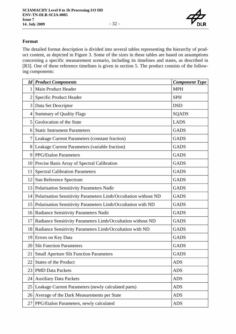
The detailed format description is divided into several tables representing the hierarchy of prod-uct content, as depicted in Figure 3. Some of the sizes in these tables are based on assumptions concerning a specific measurement scenario, including its timelines and states, as described in [R3]. One of these reference timelines is given in section 5. The product consists of the follow-ing components:
Id Product Components Component Type1 Main Product Header MPH
2 Specific Product Header SPH
3 Data Set Descriptor DSD
4 Summary of Quality Flags SQADS
5 Geolocation of the State LADS
6 Static Instrument Parameters GADS
7 Leakage Current Parameters (constant fraction) GADS
8 Leakage Current Parameters (variable fraction) GADS
9 PPG/Etalon Parameters GADS
10 Precise Basis Array of Spectral Calibration GADS
11 Spectral Calibration Parameters GADS
12 Sun Reference Spectrum GADS
13 Polarisation Sensitivity Parameters Nadir GADS
14 Polarisation Sensitivity Parameters Limb/Occultation without ND GADS
15 Polarisation Sensitivity Parameters Limb/Occultation with ND GADS
16 Radiance Sensitivity Parameters Nadir GADS
17 Radiance Sensitivity Parameters Limb/Occultation without ND GADS
18 Radiance Sensitivity Parameters Limb/Occultation with ND GADS
19 Errors on Key Data GADS
20 Slit Function Parameters GADS
21 Small Aperture Slit Function Parameters GADS
22 States of the Product ADS
23 PMD Data Packets ADS
24 Auxiliary Data Packets ADS
25 Leakage Current Parameters (newly calculated parts) ADS
26 Average of the Dark Measurements per State ADS
27 PPG/Etalon Parameters, newly calculated ADS
SCIAMACHY Level 0 to 1b Processing I/O DD ENV-TN-DLR-SCIA-0005
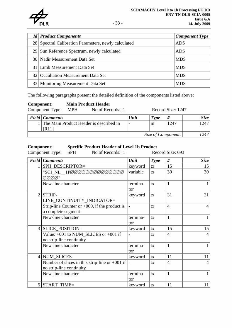
Issue 6/A 14. July 2009 - 33 -
Id Product Components Component Type28 Spectral Calibration Parameters, newly calculated ADS
29 Sun Reference Spectrum, newly calculated ADS
30 Nadir Measurement Data Set MDS
31 Limb Measurement Data Set MDS
32 Occultation Measurement Data Set MDS
33 Monitoring Measurement Data Set MDS
The following paragraphs present the detailed definition of the components listed above:
Component: Main Product Header Component Type: MPH No of Records: 1 Record Size: 1247 Field Comments Unit Type # Size
1 The Main Product Header is described in [R11]
- m 1247 1247
Size of Component: 1247
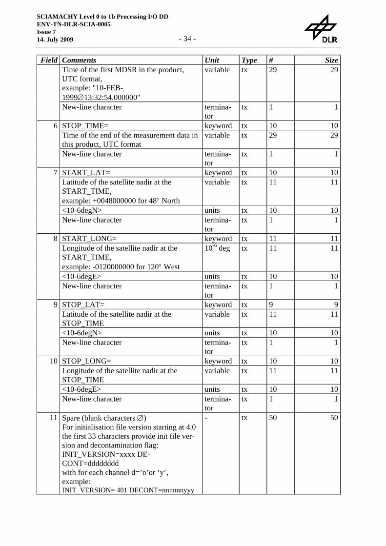
Component: Specific Product Header of Level 1b Product Component Type: SPH No of Records: 1 Record Size: 693 Field Comments Unit Type # Size
SPH_DESCRIPTOR= keyword tx 15 15"SCI_NL__1P∅∅∅∅∅∅∅∅∅∅∅∅∅∅∅∅∅∅"
variable tx 30 301
New-line character termina-tor
tx 1 1
STRIP-LINE_CONTINUITY_INDICATOR=
keyword tx 31 31
Strip-line Counter or +000, if the product is a complete segment
- tx 4 4
2
New-line character termina-tor
tx 1 1
SLICE_POSITION= keyword tx 15 15Value: +001 to NUM_SLICES or +001 if no strip-line continuity
- tx 4 43
New-line character termina-tor
tx 1 1
NUM_SLICES keyword tx 11 11Number of slices in this strip-line or +001 if no strip-line continuity
- tx 4 44
New-line character termina-tor
tx 1 1
5 START_TIME= keyword tx 11 11
SCIAMACHY Level 0 to 1b Processing I/O DD ENV-TN-DLR-SCIA-0005 Issue 7 14. July 2009 - 34 -
Field Comments Unit Type # SizeTime of the first MDSR in the product, UTC format, example: "10-FEB-1999∅13:32:54.000000"
variable tx 29 29
New-line character termina-tor
tx 1 1
STOP_TIME= keyword tx 10 10Time of the end of the measurement data in this product, UTC format
variable tx 29 296
New-line character termina-tor
tx 1 1
START_LAT= keyword tx 10 10Latitude of the satellite nadir at the START_TIME, example: +0048000000 for 48° North
variable tx 11 11
<10-6degN> units tx 10 10
7
New-line character termina-tor
tx 1 1
START_LONG= keyword tx 11 11Longitude of the satellite nadir at the START_TIME, example: -0120000000 for 120° West
10-6 deg tx 11 11
<10-6degE> units tx 10 10
8
New-line character termina-tor
tx 1 1
STOP_LAT= keyword tx 9 9Latitude of the satellite nadir at the STOP_TIME
variable tx 11 11
<10-6degN> units tx 10 10
9
New-line character termina-tor
tx 1 1
STOP_LONG= keyword tx 10 10Longitude of the satellite nadir at the STOP_TIME
variable tx 11 11
<10-6degE> units tx 10 10
10
New-line character termina-tor
tx 1 1
11 Spare (blank characters ∅) For initialisation file version starting at 4.0 the first 33 characters provide init file ver-sion and decontamination flag: INIT_VERSION=xxxx DE-CONT=dddddddd with for each channel d=’n’or ‘y’, example: INIT_VERSION= 401 DECONT=nnnnnnyyy
- tx 50 50
SCIAMACHY Level 0 to 1b Processing I/O DD ENV-TN-DLR-SCIA-0005
Issue 6/A 14. July 2009 - 35 -
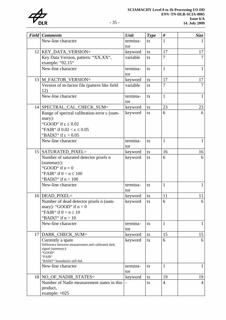
Field Comments Unit Type # SizeNew-line character termina-
tor tx 1 1
KEY_DATA_VERSION= keyword tx 17 17Key Data Version, pattern: “XX.XX“, example: “02.15“
variable tx 7 712
New-line character termina-tor
tx 1 1
M_FACTOR_VERSION= keyword tx 17 17Version of m-factor file (pattern like field 12)
variable tx 7 713
New-line character termina-tor
tx 1 1
SPECTRAL_CAL_CHECK_SUM= keyword tx 23 23Range of spectral calibration error ε (sum-mary): “GOOD“ if ε ≤ 0.02 “FAIR“ if 0.02 < ε ≤ 0.05 “BAD∅“ if ε > 0.05
keyword tx 6 614
New-line character termina-tor
tx 1 1
SATURATED_PIXEL= keyword tx 16 16Number of saturated detector pixels n (summary): “GOOD“ if n = 0 “FAIR“ if 0 < n ≤ 100 “BAD∅“ if n > 100
keyword tx 6 615
New-line character termina-tor
tx 1 1
DEAD_PIXEL= keyword tx 11 11Number of dead detector pixels n (sum-mary): “GOOD“ if n = 0 “FAIR“ if 0 < n ≤ 10 “BAD∅“ if n > 10
keyword tx 6 616
New-line character termina-tor
tx 1 1
DARK_CHECK_SUM= keyword tx 15 15Currently a spare Difference between measurement and calibrated dark signal (summary): “GOOD“ “FAIR“ “BAD∅“ boundaries still tbd.
keyword tx 6 617
New-line character termina-tor
tx 1 1
NO_OF_NADIR_STATES= keyword tx 19 1918 Number of Nadir measurement states in this product, example: +025
- tx 4 4
SCIAMACHY Level 0 to 1b Processing I/O DD ENV-TN-DLR-SCIA-0005 Issue 7 14. July 2009 - 36 -
Field Comments Unit Type # SizeNew-line character termina-
tor tx 1 1
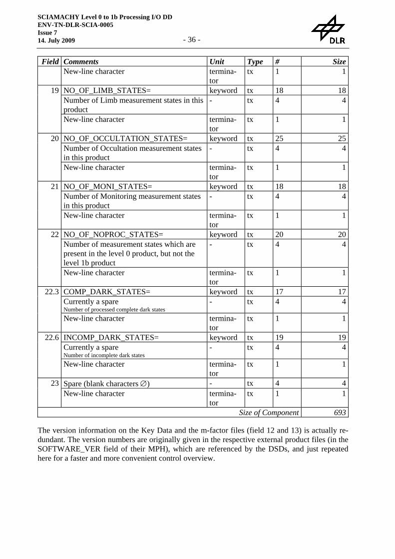
NO_OF_LIMB_STATES= keyword tx 18 18Number of Limb measurement states in this product
- tx 4 419
New-line character termina-tor
tx 1 1
NO_OF_OCCULTATION_STATES= keyword tx 25 25Number of Occultation measurement states in this product
- tx 4 420
New-line character termina-tor
tx 1 1
NO_OF_MONI_STATES= keyword tx 18 18Number of Monitoring measurement states in this product
- tx 4 421
New-line character termina-tor
tx 1 1
NO_OF_NOPROC_STATES= keyword tx 20 20Number of measurement states which are present in the level 0 product, but not the level 1b product
- tx 4 422
New-line character termina-tor
tx 1 1
COMP_DARK_STATES= keyword tx 17 17Currently a spare Number of processed complete dark states
- tx 4 422.3
New-line character termina-tor
tx 1 1
INCOMP_DARK_STATES= keyword tx 19 19Currently a spare Number of incomplete dark states
- tx 4 422.6
New-line character termina-tor
tx 1 1
Spare (blank characters ∅) - tx 4 423 New-line character termina-
tor tx 1 1
Size of Component 693
The version information on the Key Data and the m-factor files (field 12 and 13) is actually re-dundant. The version numbers are originally given in the respective external product files (in the SOFTWARE_VER field of their MPH), which are referenced by the DSDs, and just repeated here for a faster and more convenient control overview.
SCIAMACHY Level 0 to 1b Processing I/O DD ENV-TN-DLR-SCIA-0005
Issue 6/A 14. July 2009 - 37 -
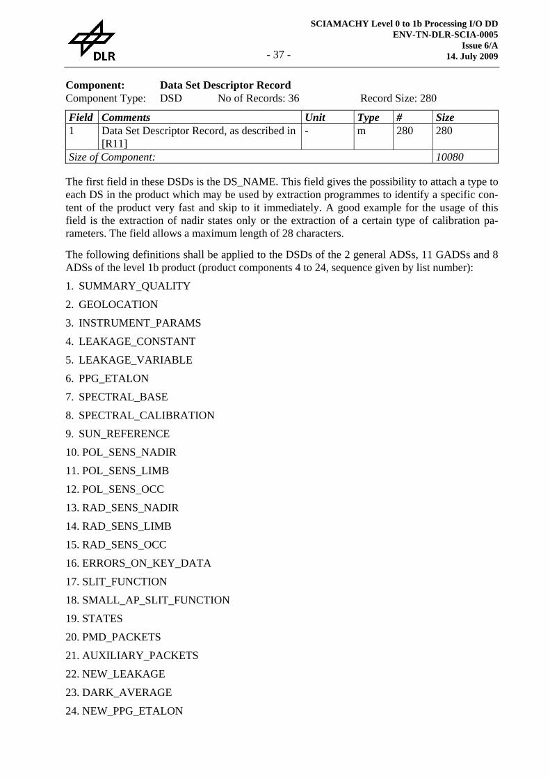
Component: Data Set Descriptor Record Component Type: DSD No of Records: 36 Record Size: 280 Field Comments Unit Type # Size 1 Data Set Descriptor Record, as described in
[R11] - m 280 280
Size of Component: 10080
The first field in these DSDs is the DS_NAME. This field gives the possibility to attach a type to each DS in the product which may be used by extraction programmes to identify a specific con-tent of the product very fast and skip to it immediately. A good example for the usage of this field is the extraction of nadir states only or the extraction of a certain type of calibration pa-rameters. The field allows a maximum length of 28 characters.
The following definitions shall be applied to the DSDs of the 2 general ADSs, 11 GADSs and 8 ADSs of the level 1b product (product components 4 to 24, sequence given by list number):
1. SUMMARY_QUALITY
2. GEOLOCATION
3. INSTRUMENT_PARAMS
4. LEAKAGE_CONSTANT
5. LEAKAGE_VARIABLE
6. PPG_ETALON
7. SPECTRAL_BASE
8. SPECTRAL_CALIBRATION
9. SUN_REFERENCE
10. POL_SENS_NADIR
11. POL_SENS_LIMB
12. POL_SENS_OCC
13. RAD_SENS_NADIR
14. RAD_SENS_LIMB
15. RAD_SENS_OCC
16. ERRORS_ON_KEY_DATA
17. SLIT_FUNCTION
18. SMALL_AP_SLIT_FUNCTION
19. STATES
20. PMD_PACKETS
21. AUXILIARY_PACKETS
22. NEW_LEAKAGE
23. DARK_AVERAGE
24. NEW_PPG_ETALON
SCIAMACHY Level 0 to 1b Processing I/O DD ENV-TN-DLR-SCIA-0005 Issue 7 14. July 2009 - 38 -
25. NEW_SPECTRAL_CALIBRATION
26. NEW_SUN_REFERENCE
The annotation data sets whose names are starting with "NEW_" are not necessarily part of the product, because they are only present when the corresponding in-flight calibration measure-ments have been processed. In case they are not present the FILENAME field of the DSD record shall be filled with "NOT USED".
The following data set names shall be used for the 4 MDSs:
27. NADIR
28. LIMB
29. OCCULTATION
30. MONITORING
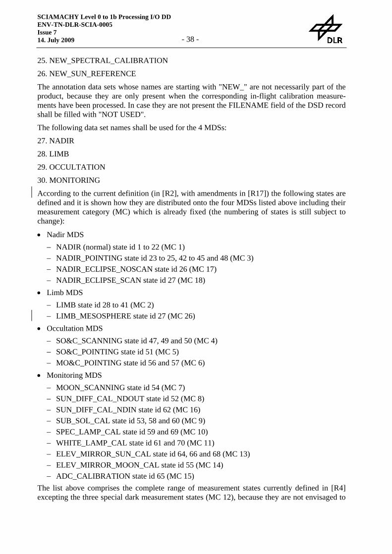
According to the current definition (in [R2], with amendments in [R17]) the following states are defined and it is shown how they are distributed onto the four MDSs listed above including their measurement category (MC) which is already fixed (the numbering of states is still subject to change):
• Nadir MDS − NADIR (normal) state id 1 to 22 (MC 1) − NADIR_POINTING state id 23 to 25, 42 to 45 and 48 (MC 3) − NADIR_ECLIPSE_NOSCAN state id 26 (MC 17) − NADIR_ECLIPSE_SCAN state id 27 (MC 18)
• Limb MDS − LIMB state id 28 to 41 (MC 2) − LIMB_MESOSPHERE state id 27 (MC 26)
• Occultation MDS − SO&C_SCANNING state id 47, 49 and 50 (MC 4) − SO&C_POINTING state id 51 (MC 5) − MO&C_POINTING state id 56 and 57 (MC 6)
• Monitoring MDS − MOON_SCANNING state id 54 (MC 7) − SUN_DIFF_CAL_NDOUT state id 52 (MC 8) − SUN_DIFF_CAL_NDIN state id 62 (MC 16) − SUB_SOL_CAL state id 53, 58 and 60 (MC 9) − SPEC_LAMP_CAL state id 59 and 69 (MC 10) − WHITE_LAMP_CAL state id 61 and 70 (MC 11) − ELEV_MIRROR_SUN_CAL state id 64, 66 and 68 (MC 13) − ELEV_MIRROR_MOON_CAL state id 55 (MC 14) − ADC_CALIBRATION state id 65 (MC 15)
The list above comprises the complete range of measurement states currently defined in [R4] excepting the three special dark measurement states (MC 12), because they are not envisaged to
SCIAMACHY Level 0 to 1b Processing I/O DD ENV-TN-DLR-SCIA-0005
Issue 6/A 14. July 2009 - 39 -
provide more information for any type of scientific or monitoring application on top of the exist-ing leakage current GADSs in the product.
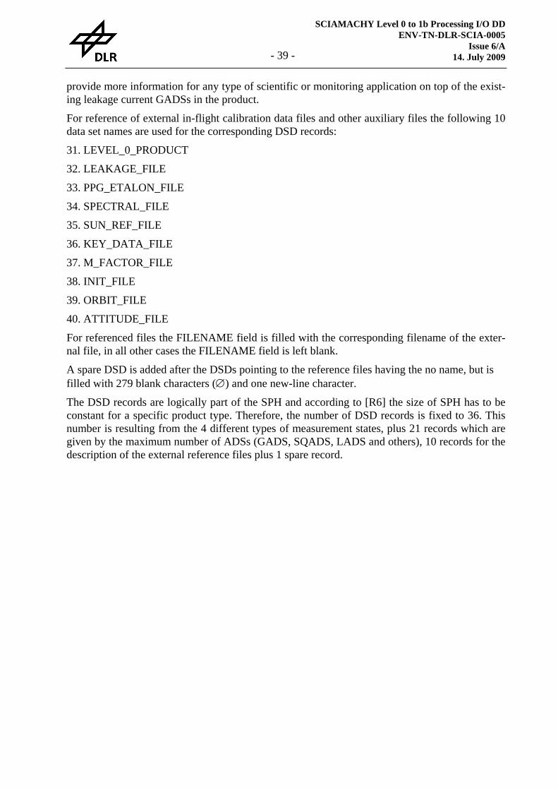
For reference of external in-flight calibration data files and other auxiliary files the following 10 data set names are used for the corresponding DSD records:
31. LEVEL_0_PRODUCT
32. LEAKAGE_FILE
33. PPG_ETALON_FILE
34. SPECTRAL_FILE
35. SUN_REF_FILE
36. KEY_DATA_FILE
37. M_FACTOR_FILE
38. INIT_FILE
39. ORBIT_FILE
40. ATTITUDE_FILE
For referenced files the FILENAME field is filled with the corresponding filename of the exter-nal file, in all other cases the FILENAME field is left blank.
A spare DSD is added after the DSDs pointing to the reference files having the no name, but is filled with 279 blank characters (∅) and one new-line character.
The DSD records are logically part of the SPH and according to [R6] the size of SPH has to be constant for a specific product type. Therefore, the number of DSD records is fixed to 36. This number is resulting from the 4 different types of measurement states, plus 21 records which are given by the maximum number of ADSs (GADS, SQADS, LADS and others), 10 records for the description of the external reference files plus 1 spare record.
SCIAMACHY Level 0 to 1b Processing I/O DD ENV-TN-DLR-SCIA-0005 Issue 7 14. July 2009 - 40 -
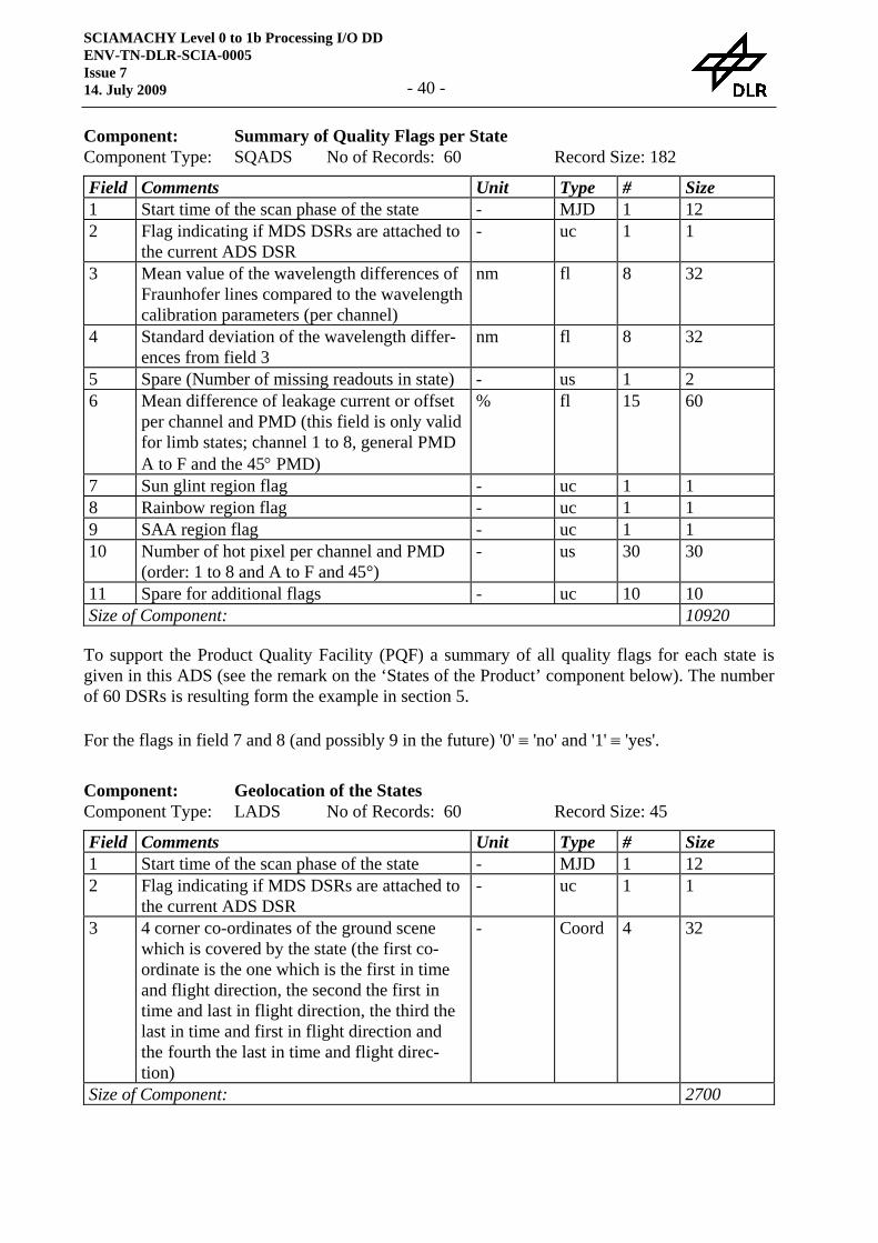
Component: Summary of Quality Flags per State Component Type: SQADS No of Records: 60 Record Size: 182 Field Comments Unit Type # Size 1 Start time of the scan phase of the state - MJD 1 12 2 Flag indicating if MDS DSRs are attached to
the current ADS DSR - uc 1 1
3 Mean value of the wavelength differences of Fraunhofer lines compared to the wavelength calibration parameters (per channel)
nm fl 8 32
4 Standard deviation of the wavelength differ-ences from field 3
nm fl 8 32
5 Spare (Number of missing readouts in state) - us 1 2 6 Mean difference of leakage current or offset
per channel and PMD (this field is only valid for limb states; channel 1 to 8, general PMD A to F and the 45° PMD)
% fl 15 60
7 Sun glint region flag - uc 1 1 8 Rainbow region flag - uc 1 1 9 SAA region flag - uc 1 1 10 Number of hot pixel per channel and PMD
(order: 1 to 8 and A to F and 45°) - us 30 30
11 Spare for additional flags - uc 10 10 Size of Component: 10920
To support the Product Quality Facility (PQF) a summary of all quality flags for each state is given in this ADS (see the remark on the ‘States of the Product’ component below). The number of 60 DSRs is resulting form the example in section 5.
For the flags in field 7 and 8 (and possibly 9 in the future) '0' ≡ 'no' and '1' ≡ 'yes'.
Component: Geolocation of the States Component Type: LADS No of Records: 60 Record Size: 45 Field Comments Unit Type # Size 1 Start time of the scan phase of the state - MJD 1 12 2 Flag indicating if MDS DSRs are attached to
the current ADS DSR - uc 1 1
3 4 corner co-ordinates of the ground scene which is covered by the state (the first co-ordinate is the one which is the first in time and flight direction, the second the first in time and last in flight direction, the third the last in time and first in flight direction and the fourth the last in time and flight direc-tion)
- Coord 4 32
Size of Component: 2700

SCIAMACHY Level 0 to 1b Processing I/O DD ENV-TN-DLR-SCIA-0005
Issue 6/A 14. July 2009 - 41 -
To support the extraction of SCIAMACHY data according to a given geolocation this ADS gives the geolocation (4 corner co-ordinates) of the scene on ground which is covered by each states (see the remark on the ‘States of the Product’ component below). The number of 60 DSRs is resulting form the example in section 5.
For Limb and occultation measurements the co-ordinates are representing the tangent ground points of the beginning and the end of the state and for all other measurements (calibration and monitoring) these co-ordinates shall be filled with the sub-satellite point at the beginning and the end of the state. In theses cases the first and the second as well as the third and fourth co-ordinates have the same values.
SCIAMACHY Level 0 to 1b Processing I/O DD ENV-TN-DLR-SCIA-0005 Issue 7 14. July 2009 - 42 -
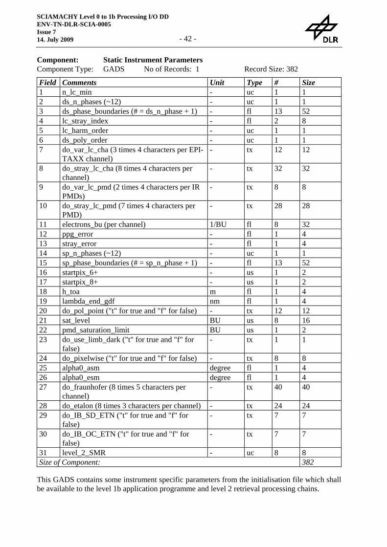
Component: Static Instrument Parameters Component Type: GADS No of Records: 1 Record Size: 382 Field Comments Unit Type # Size 1 n_lc_min - uc 1 1 2 ds_n_phases (~12) - uc 1 1 3 ds_phase_boundaries (# = ds_n_phase + 1) - fl 13 52 4 lc_stray_index - fl 2 8 5 lc_harm_order - uc 1 1 6 ds_poly_order - uc 1 1 7 do_var_lc_cha (3 times 4 characters per EPI-
TAXX channel) - tx 12 12
8 do_stray_lc_cha (8 times 4 characters per channel)
- tx 32 32
9 do_var_lc_pmd (2 times 4 characters per IR PMDs)
- tx 8 8
10 do_stray_lc_pmd (7 times 4 characters per PMD)
- tx 28 28
11 electrons_bu (per channel) 1/BU fl 8 32 12 ppg_error - fl 1 4 13 stray_error - fl 1 4 14 sp_n_phases (~12) - uc 1 1 15 sp_phase_boundaries (# = sp_n_phase + 1) - fl 13 52 16 startpix_6+ - us 1 2 17 startpix_8+ - us 1 2 18 h_toa m fl 1 4 19 lambda_end_gdf nm fl 1 4 20 do_pol_point ("t" for true and "f" for false) - tx 12 12 21 sat_level BU us 8 16 22 pmd_saturation_limit BU us 1 2 23 do_use_limb_dark ("t" for true and "f" for
false) - tx 1 1
24 do_pixelwise ("t" for true and "f" for false) - tx 8 8 25 alpha0_asm degree fl 1 4 26 alpha0_esm degree fl 1 4 27 do_fraunhofer (8 times 5 characters per
channel) - tx 40 40
28 do_etalon (8 times 3 characters per channel) - tx 24 24 29 do_IB_SD_ETN ("t" for true and "f" for
false) - tx 7 7
30 do_IB_OC_ETN ("t" for true and "f" for false)
- tx 7 7
31 level_2_SMR - uc 8 8 Size of Component: 382
This GADS contains some instrument specific parameters from the initialisation file which shall be available to the level 1b application programme and level 2 retrieval processing chains.
SCIAMACHY Level 0 to 1b Processing I/O DD ENV-TN-DLR-SCIA-0005
Issue 6/A 14. July 2009 - 43 -
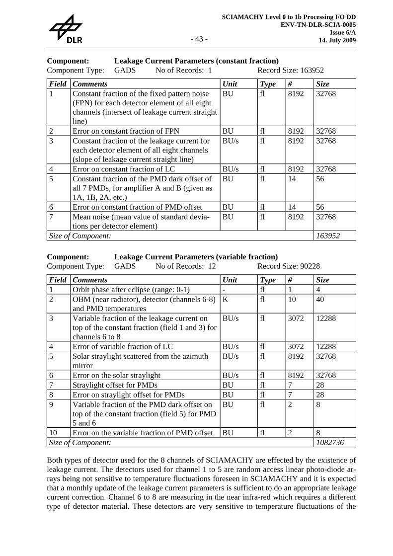
Component: Leakage Current Parameters (constant fraction) Component Type: GADS No of Records: 1 Record Size: 163952 Field Comments Unit Type # Size 1 Constant fraction of the fixed pattern noise
(FPN) for each detector element of all eight channels (intersect of leakage current straight line)
BU fl 8192 32768
2 Error on constant fraction of FPN BU fl 8192 32768 3 Constant fraction of the leakage current for
each detector element of all eight channels (slope of leakage current straight line)
BU/s fl 8192 32768
4 Error on constant fraction of LC BU/s fl 8192 32768 5 Constant fraction of the PMD dark offset of
all 7 PMDs, for amplifier A and B (given as 1A, 1B, 2A, etc.)
BU fl 14 56
6 Error on constant fraction of PMD offset BU fl 14 56 7 Mean noise (mean value of standard devia-
tions per detector element) BU fl 8192 32768
Size of Component: 163952
Component: Leakage Current Parameters (variable fraction) Component Type: GADS No of Records: 12 Record Size: 90228 Field Comments Unit Type # Size 1 Orbit phase after eclipse (range: 0-1) - fl 1 4 2 OBM (near radiator), detector (channels 6-8)
and PMD temperatures K fl 10 40
3 Variable fraction of the leakage current on top of the constant fraction (field 1 and 3) for channels 6 to 8
BU/s fl 3072 12288
4 Error of variable fraction of LC BU/s fl 3072 12288 5 Solar straylight scattered from the azimuth
mirror BU/s fl 8192 32768
6 Error on the solar straylight BU/s fl 8192 32768 7 Straylight offset for PMDs BU fl 7 28 8 Error on straylight offset for PMDs BU fl 7 28 9 Variable fraction of the PMD dark offset on
top of the constant fraction (field 5) for PMD 5 and 6
BU fl 2 8
10 Error on the variable fraction of PMD offset BU fl 2 8 Size of Component: 1082736
Both types of detector used for the 8 channels of SCIAMACHY are effected by the existence of leakage current. The detectors used for channel 1 to 5 are random access linear photo-diode ar-rays being not sensitive to temperature fluctuations foreseen in SCIAMACHY and it is expected that a monthly update of the leakage current parameters is sufficient to do an appropriate leakage current correction. Channel 6 to 8 are measuring in the near infra-red which requires a different type of detector material. These detectors are very sensitive to temperature fluctuations of the
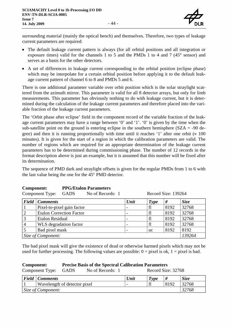
SCIAMACHY Level 0 to 1b Processing I/O DD ENV-TN-DLR-SCIA-0005 Issue 7 14. July 2009 - 44 -
surrounding material (mainly the optical bench) and themselves. Therefore, two types of leakage current parameters are required:
• The default leakage current pattern is always (for all orbital positions and all integration or exposure times) valid for the channels 1 to 5 and the PMDs 1 to 4 and 7 (45° sensor) and serves as a basis for the other detectors.
• A set of differences in leakage current corresponding to the orbital position (eclipse phase) which may be interpolate for a certain orbital position before applying it to the default leak-age current pattern of channel 6 to 8 and PMDs 5 and 6.
There is one additional parameter variable over orbit position which is the solar straylight scat-tered from the azimuth mirror. This parameter is valid for all 8 detector arrays, but only for limb measurements. This parameter has obviously nothing to do with leakage current, but it is deter-mined during the calculation of the leakage current parameters and therefore placed into the vari-able fraction of the leakage current parameters.
The ‘Orbit phase after eclipse’ field in the component record of the variable fraction of the leak-age current parameters may have a range between ‘0’ and ‘1’. ‘0’ is given by the time when the sub-satellite point on the ground is entering eclipse in the southern hemisphere (SZA = -90 de-gree) and then it is running proportionally with time until it reaches ‘1’ after one orbit (≈ 100 minutes). It is given for the start of a region in which the calibration parameters are valid. The number of regions which are required for an appropriate determination of the leakage current parameters has to be determined during commissioning phase. The number of 12 records in the format description above is just an example, but it is assumed that this number will be fixed after its determination.
The sequence of PMD dark and straylight offsets is given for the regular PMDs from 1 to 6 with the last value being the one for the 45° PMD detector.
Component: PPG/Etalon Parameters Component Type: GADS No of Records: 1 Record Size: 139264 Field Comments Unit Type # Size 1 Pixel-to-pixel gain factor - fl 8192 32768 2 Etalon Correction Factor - fl 8192 32768 3 Etalon Residual - fl 8192 32768 4 WLS degradation factor - fl 8192 32768 5 Bad pixel mask - uc 8192 8192 Size of Component: 139264
The bad pixel mask will give the existence of dead or otherwise harmed pixels which may not be used for further processing. The following values are possible: 0 = pixel is ok, 1 = pixel is bad.
Component: Precise Basis of the Spectral Calibration Parameters Component Type: GADS No of Records: 1 Record Size: 32768 Field Comments Unit Type # Size 1 Wavelength of detector pixel - fl 8192 32768 Size of Component: 32768
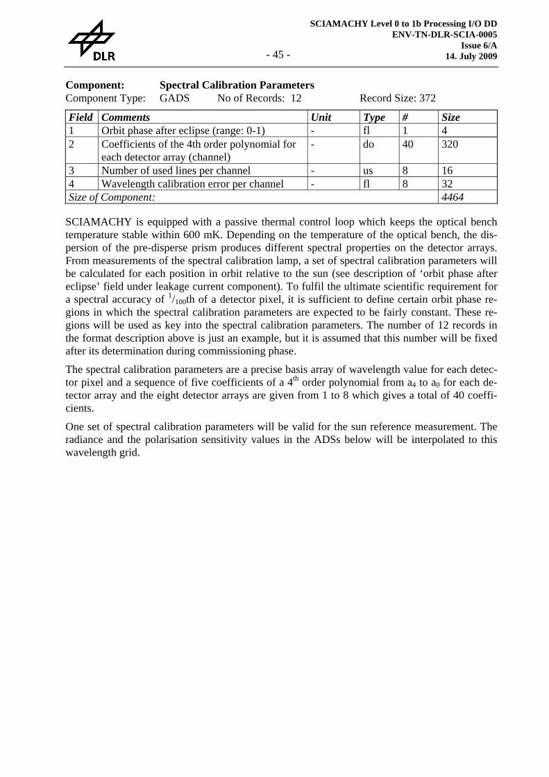
SCIAMACHY Level 0 to 1b Processing I/O DD ENV-TN-DLR-SCIA-0005
Issue 6/A 14. July 2009 - 45 -
Component: Spectral Calibration Parameters Component Type: GADS No of Records: 12 Record Size: 372 Field Comments Unit Type # Size 1 Orbit phase after eclipse (range: 0-1) - fl 1 4 2 Coefficients of the 4th order polynomial for
each detector array (channel) - do 40 320
3 Number of used lines per channel - us 8 16 4 Wavelength calibration error per channel - fl 8 32 Size of Component: 4464
SCIAMACHY is equipped with a passive thermal control loop which keeps the optical bench temperature stable within 600 mK. Depending on the temperature of the optical bench, the dis-persion of the pre-disperse prism produces different spectral properties on the detector arrays. From measurements of the spectral calibration lamp, a set of spectral calibration parameters will be calculated for each position in orbit relative to the sun (see description of ‘orbit phase after eclipse’ field under leakage current component). To fulfil the ultimate scientific requirement for a spectral accuracy of 1/100th of a detector pixel, it is sufficient to define certain orbit phase re-gions in which the spectral calibration parameters are expected to be fairly constant. These re-gions will be used as key into the spectral calibration parameters. The number of 12 records in the format description above is just an example, but it is assumed that this number will be fixed after its determination during commissioning phase.
The spectral calibration parameters are a precise basis array of wavelength value for each detec-tor pixel and a sequence of five coefficients of a 4th order polynomial from a4 to a0 for each de-tector array and the eight detector arrays are given from 1 to 8 which gives a total of 40 coeffi-cients.
One set of spectral calibration parameters will be valid for the sun reference measurement. The radiance and the polarisation sensitivity values in the ADSs below will be interpolated to this wavelength grid.
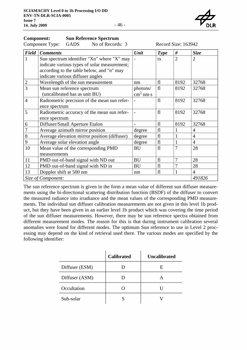
SCIAMACHY Level 0 to 1b Processing I/O DD ENV-TN-DLR-SCIA-0005 Issue 7 14. July 2009 - 46 -
Component: Sun Reference Spectrum Component Type: GADS No of Records: 3 Record Size: 163942 Field Comments Unit Type # Size 1 Sun spectrum identifier "Xn" where "X" may
indicate various types of solar measurement; according to the table below, and "n" may indicate various diffuser angles
- tx 2 2
2 Wavelength of the sun measurement nm fl 8192 32768 3 Mean sun reference spectrum
(uncalibrated has as unit BU) photons/ cm2⋅nm⋅s
fl 8192 32768
4 Radiometric precision of the mean sun refer-ence spectrum
- fl 8192 32768
5 Radiometric accuracy of the mean sun refer-ence spectrum
- fl 8192 32768
6 Diffuser/Small Aperture Etalon - fl 8192 32768 7 Average azimuth mirror position degree fl 1 4 8 Average elevation mirror position (diffuser) degree fl 1 4 9 Average solar elevation angle degree fl 1 4 10 Mean value of the corresponding PMD
measurements BU fl 7 28
11 PMD out-of-band signal with ND out BU fl 7 28 12 PMD out-of-band signal with ND in BU fl 7 28 13 Doppler shift at 500 nm nm fl 1 4 Size of Component: 491826
The sun reference spectrum is given in the form a mean value of different sun diffuser measure-ments using the bi-directional scattering distribution function (BSDF) of the diffuser to convert the measured radiance into irradiance and the mean values of the corresponding PMD measure-ments. The individual sun diffuser calibration measurements are not given in this level 1b prod-uct, but they have been given in an earlier level 1b product which was covering the time period of the sun diffuser measurements. However, there may be sun reference spectra obtained from different measurement modes. The reason for this is that during instrument calibration several anomalies were found for different modes. The optimum Sun reference to use in Level 2 proc-essing may depend on the kind of retrieval used there. The various modes are specified by the following identifier:
Calibrated Uncalibrated
Diffuser (ESM) D E
Diffuser (ASM) D A
Occultation O U
Sub-solar S V
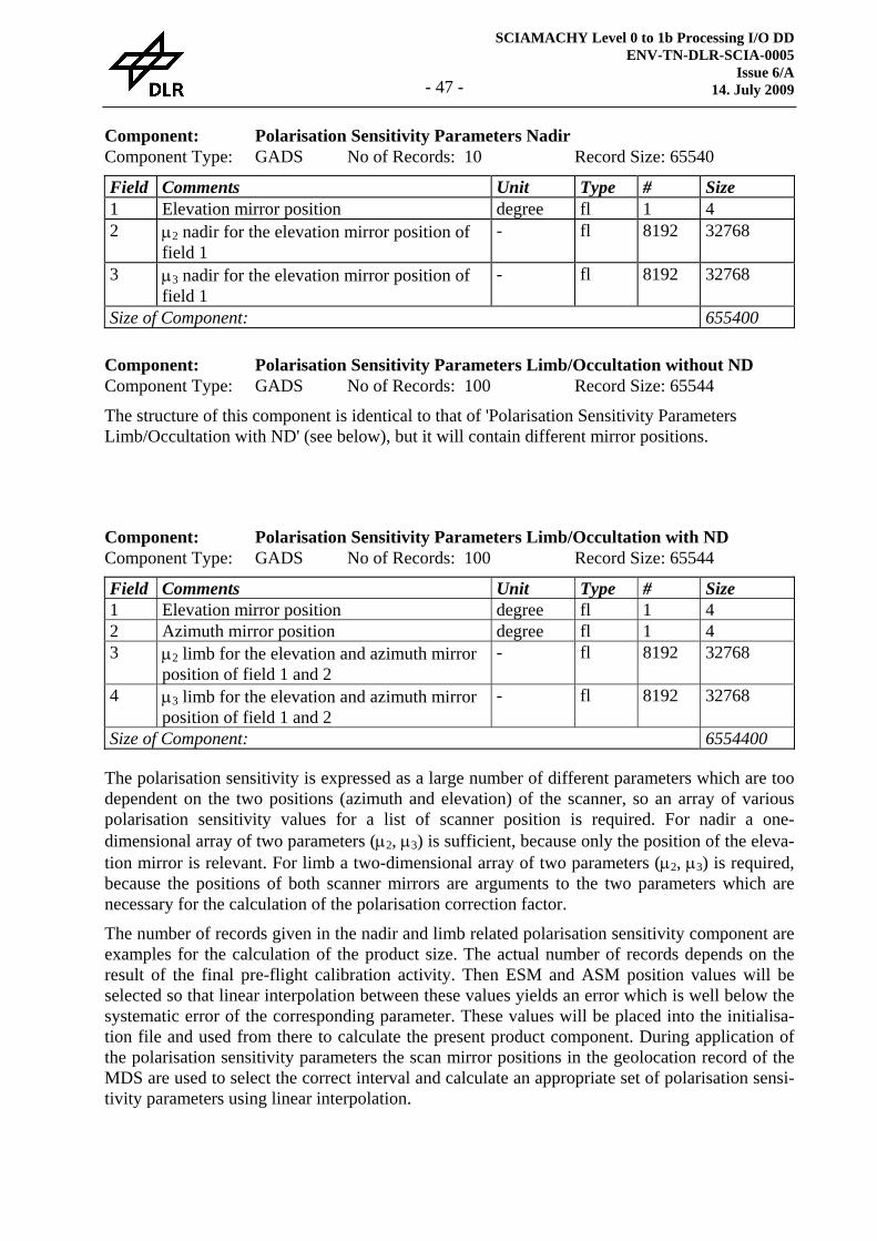
SCIAMACHY Level 0 to 1b Processing I/O DD ENV-TN-DLR-SCIA-0005
Issue 6/A 14. July 2009 - 47 -
Component: Polarisation Sensitivity Parameters Nadir Component Type: GADS No of Records: 10 Record Size: 65540 Field Comments Unit Type # Size 1 Elevation mirror position degree fl 1 4 2 μ2 nadir for the elevation mirror position of
field 1 - fl 8192 32768
3 μ3 nadir for the elevation mirror position of field 1
- fl 8192 32768
Size of Component: 655400
Component: Polarisation Sensitivity Parameters Limb/Occultation without ND Component Type: GADS No of Records: 100 Record Size: 65544
The structure of this component is identical to that of 'Polarisation Sensitivity Parameters Limb/Occultation with ND' (see below), but it will contain different mirror positions.
Component: Polarisation Sensitivity Parameters Limb/Occultation with ND Component Type: GADS No of Records: 100 Record Size: 65544 Field Comments Unit Type # Size 1 Elevation mirror position degree fl 1 4 2 Azimuth mirror position degree fl 1 4 3 μ2 limb for the elevation and azimuth mirror
position of field 1 and 2 - fl 8192 32768
4 μ3 limb for the elevation and azimuth mirror position of field 1 and 2
- fl 8192 32768
Size of Component: 6554400
The polarisation sensitivity is expressed as a large number of different parameters which are too dependent on the two positions (azimuth and elevation) of the scanner, so an array of various polarisation sensitivity values for a list of scanner position is required. For nadir a one-dimensional array of two parameters (μ2, μ3) is sufficient, because only the position of the eleva-tion mirror is relevant. For limb a two-dimensional array of two parameters (μ2, μ3) is required, because the positions of both scanner mirrors are arguments to the two parameters which are necessary for the calculation of the polarisation correction factor.
The number of records given in the nadir and limb related polarisation sensitivity component are examples for the calculation of the product size. The actual number of records depends on the result of the final pre-flight calibration activity. Then ESM and ASM position values will be selected so that linear interpolation between these values yields an error which is well below the systematic error of the corresponding parameter. These values will be placed into the initialisa-tion file and used from there to calculate the present product component. During application of the polarisation sensitivity parameters the scan mirror positions in the geolocation record of the MDS are used to select the correct interval and calculate an appropriate set of polarisation sensi-tivity parameters using linear interpolation.
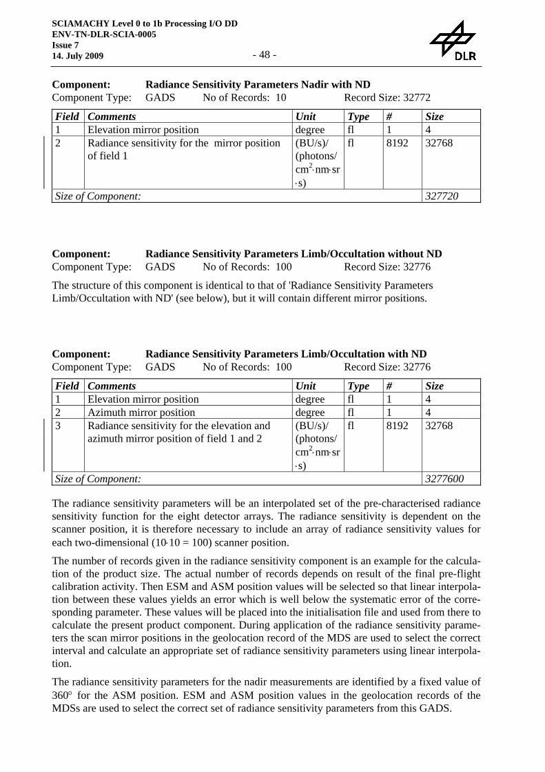
SCIAMACHY Level 0 to 1b Processing I/O DD ENV-TN-DLR-SCIA-0005 Issue 7 14. July 2009 - 48 -
Component: Radiance Sensitivity Parameters Nadir with ND Component Type: GADS No of Records: 10 Record Size: 32772 Field Comments Unit Type # Size 1 Elevation mirror position degree fl 1 4 2 Radiance sensitivity for the mirror position
of field 1 (BU/s)/ (photons/cm2⋅nm⋅sr⋅s)
fl 8192 32768
Size of Component: 327720
Component: Radiance Sensitivity Parameters Limb/Occultation without ND Component Type: GADS No of Records: 100 Record Size: 32776
The structure of this component is identical to that of 'Radiance Sensitivity Parameters Limb/Occultation with ND' (see below), but it will contain different mirror positions.
Component: Radiance Sensitivity Parameters Limb/Occultation with ND Component Type: GADS No of Records: 100 Record Size: 32776 Field Comments Unit Type # Size 1 Elevation mirror position degree fl 1 4 2 Azimuth mirror position degree fl 1 4 3 Radiance sensitivity for the elevation and
azimuth mirror position of field 1 and 2 (BU/s)/ (photons/cm2⋅nm⋅sr⋅s)
fl 8192 32768
Size of Component: 3277600
The radiance sensitivity parameters will be an interpolated set of the pre-characterised radiance sensitivity function for the eight detector arrays. The radiance sensitivity is dependent on the scanner position, it is therefore necessary to include an array of radiance sensitivity values for each two-dimensional (10⋅10 = 100) scanner position.
The number of records given in the radiance sensitivity component is an example for the calcula-tion of the product size. The actual number of records depends on result of the final pre-flight calibration activity. Then ESM and ASM position values will be selected so that linear interpola-tion between these values yields an error which is well below the systematic error of the corre-sponding parameter. These values will be placed into the initialisation file and used from there to calculate the present product component. During application of the radiance sensitivity parame-ters the scan mirror positions in the geolocation record of the MDS are used to select the correct interval and calculate an appropriate set of radiance sensitivity parameters using linear interpola-tion.
The radiance sensitivity parameters for the nadir measurements are identified by a fixed value of 360° for the ASM position. ESM and ASM position values in the geolocation records of the MDSs are used to select the correct set of radiance sensitivity parameters from this GADS.
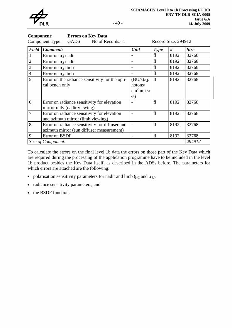
SCIAMACHY Level 0 to 1b Processing I/O DD ENV-TN-DLR-SCIA-0005
Issue 6/A 14. July 2009 - 49 -
Component: Errors on Key Data Component Type: GADS No of Records: 1 Record Size: 294912 Field Comments Unit Type # Size 1 Error on μ2 nadir - fl 8192 32768 2 Error on μ3 nadir - fl 8192 32768 3 Error on μ2 limb - fl 8192 32768 4 Error on μ3 limb - fl 8192 32768 5 Error on the radiance sensitivity for the opti-
cal bench only (BU/s)/(photons/ cm2⋅nm⋅sr⋅s)
fl 8192 32768
6 Error on radiance sensitivity for elevation mirror only (nadir viewing)
- fl 8192 32768
7 Error on radiance sensitivity for elevation and azimuth mirror (limb viewing)
- fl 8192 32768
8 Error on radiance sensitivity for diffuser and azimuth mirror (sun diffuser measurement)
- fl 8192 32768
9 Error on BSDF - fl 8192 32768 Size of Component: 294912
To calculate the errors on the final level 1b data the errors on those part of the Key Data which are required during the processing of the application programme have to be included in the level 1b product besides the Key Data itself, as described in the ADSs before. The parameters for which errors are attached are the following:
• polarisation sensitivity parameters for nadir and limb (μ2 and μ3),
• radiance sensitivity parameters, and
• the BSDF function.
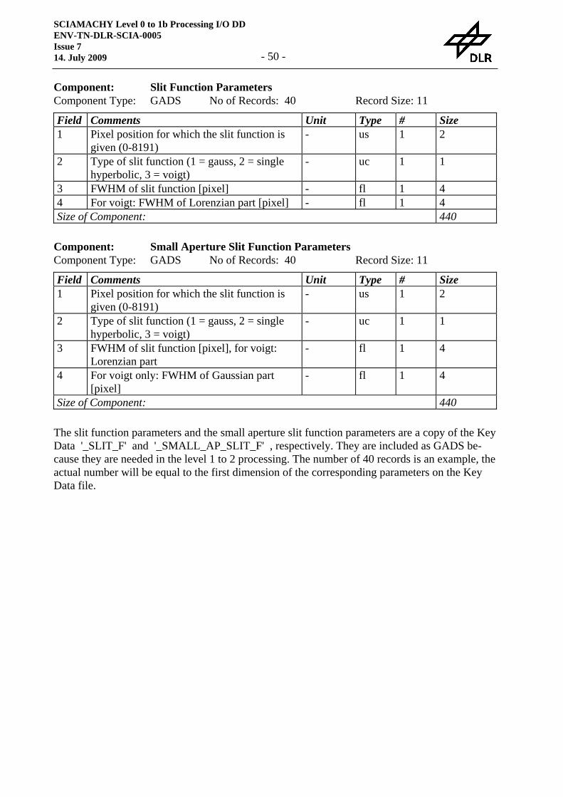
SCIAMACHY Level 0 to 1b Processing I/O DD ENV-TN-DLR-SCIA-0005 Issue 7 14. July 2009 - 50 -
Component: Slit Function Parameters Component Type: GADS No of Records: 40 Record Size: 11 Field Comments Unit Type # Size 1 Pixel position for which the slit function is
given (0-8191) - us 1 2
2 Type of slit function (1 = gauss, 2 = single hyperbolic, 3 = voigt)
- uc 1 1
3 FWHM of slit function [pixel] - fl 1 4 4 For voigt: FWHM of Lorenzian part [pixel] - fl 1 4 Size of Component: 440
Component: Small Aperture Slit Function Parameters Component Type: GADS No of Records: 40 Record Size: 11 Field Comments Unit Type # Size 1 Pixel position for which the slit function is
given (0-8191) - us 1 2
2 Type of slit function (1 = gauss, 2 = single hyperbolic, 3 = voigt)
- uc 1 1
3 FWHM of slit function [pixel], for voigt: Lorenzian part
- fl 1 4
4 For voigt only: FWHM of Gaussian part [pixel]
- fl 1 4
Size of Component: 440
The slit function parameters and the small aperture slit function parameters are a copy of the Key Data '_SLIT_F' and '_SMALL_AP_SLIT_F' , respectively. They are included as GADS be-cause they are needed in the level 1 to 2 processing. The number of 40 records is an example, the actual number will be equal to the first dimension of the corresponding parameters on the Key Data file.
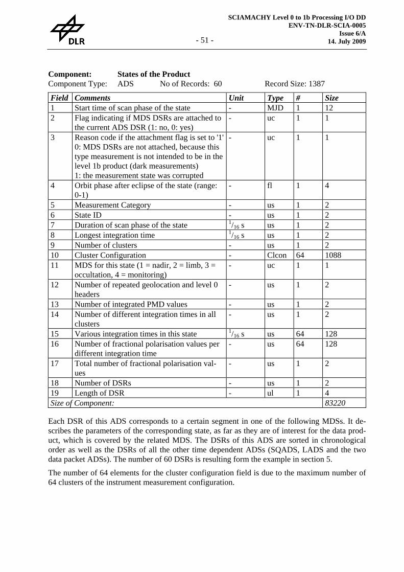
SCIAMACHY Level 0 to 1b Processing I/O DD ENV-TN-DLR-SCIA-0005
Issue 6/A 14. July 2009 - 51 -
Component: States of the Product Component Type: ADS No of Records: 60 Record Size: 1387
Field Comments Unit Type # Size 1 Start time of scan phase of the state - MJD 1 12 2 Flag indicating if MDS DSRs are attached to
the current ADS DSR (1: no, 0: yes) - uc 1 1
3 Reason code if the attachment flag is set to '1'0: MDS DSRs are not attached, because this type measurement is not intended to be in the level 1b product (dark measurements) 1: the measurement state was corrupted
- uc 1 1
4 Orbit phase after eclipse of the state (range: 0-1)
- fl 1 4
5 Measurement Category - us 1 2 6 State ID - us 1 2 7 Duration of scan phase of the state 1/16 s us 1 2 8 Longest integration time 1/16 s us 1 2 9 Number of clusters - us 1 2 10 Cluster Configuration - Clcon 64 1088 11 MDS for this state (1 = nadir, 2 = limb, 3 =
occultation, 4 = monitoring) - uc 1 1
12 Number of repeated geolocation and level 0 headers
- us 1 2
13 Number of integrated PMD values - us 1 2 14 Number of different integration times in all
clusters - us 1 2
15 Various integration times in this state 1/16 s us 64 128 16 Number of fractional polarisation values per
different integration time - us 64 128
17 Total number of fractional polarisation val-ues
- us 1 2
18 Number of DSRs - us 1 2 19 Length of DSR - ul 1 4 Size of Component: 83220
Each DSR of this ADS corresponds to a certain segment in one of the following MDSs. It de-scribes the parameters of the corresponding state, as far as they are of interest for the data prod-uct, which is covered by the related MDS. The DSRs of this ADS are sorted in chronological order as well as the DSRs of all the other time dependent ADSs (SQADS, LADS and the two data packet ADSs). The number of 60 DSRs is resulting form the example in section 5.
The number of 64 elements for the cluster configuration field is due to the maximum number of 64 clusters of the instrument measurement configuration.
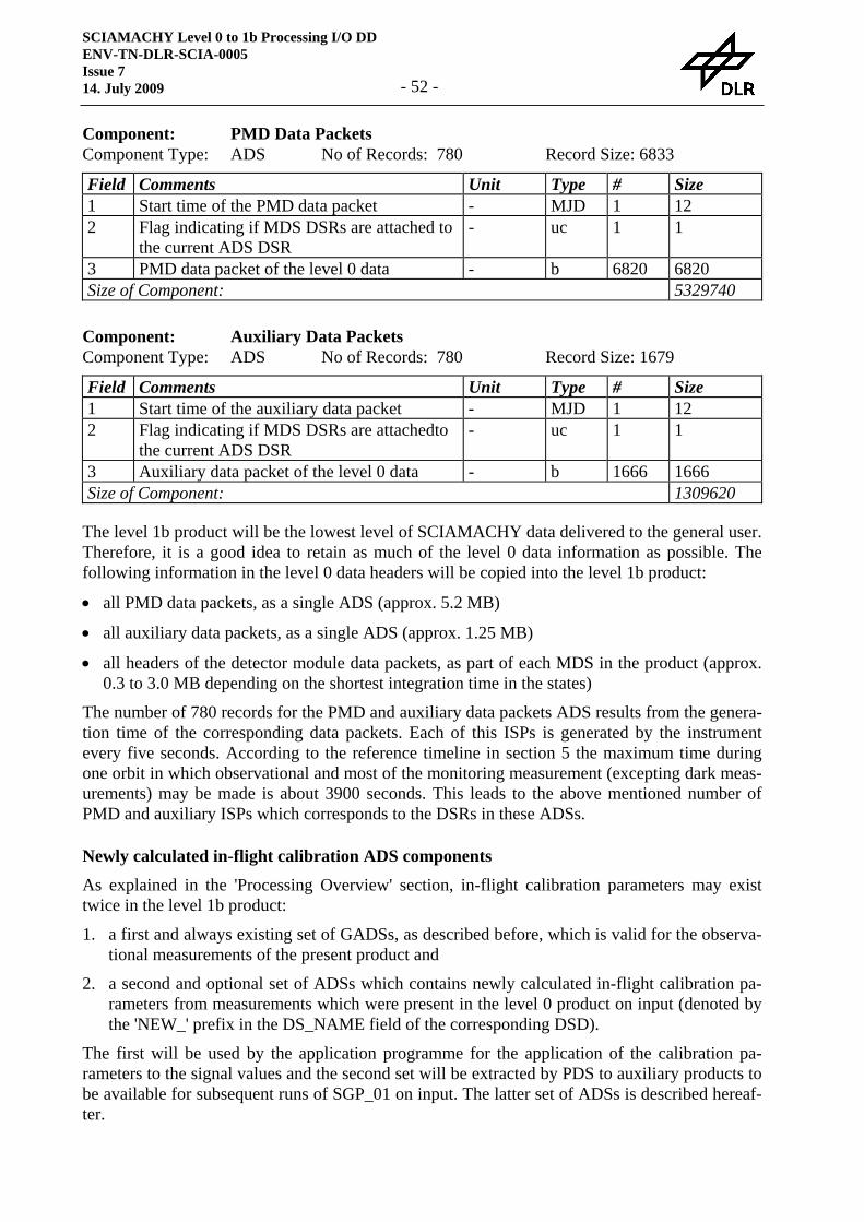
SCIAMACHY Level 0 to 1b Processing I/O DD ENV-TN-DLR-SCIA-0005 Issue 7 14. July 2009 - 52 -
Component: PMD Data Packets Component Type: ADS No of Records: 780 Record Size: 6833 Field Comments Unit Type # Size 1 Start time of the PMD data packet - MJD 1 12 2 Flag indicating if MDS DSRs are attached to
the current ADS DSR - uc 1 1
3 PMD data packet of the level 0 data - b 6820 6820 Size of Component: 5329740
Component: Auxiliary Data Packets Component Type: ADS No of Records: 780 Record Size: 1679 Field Comments Unit Type # Size 1 Start time of the auxiliary data packet - MJD 1 12 2 Flag indicating if MDS DSRs are attachedto
the current ADS DSR - uc 1 1
3 Auxiliary data packet of the level 0 data - b 1666 1666 Size of Component: 1309620
The level 1b product will be the lowest level of SCIAMACHY data delivered to the general user. Therefore, it is a good idea to retain as much of the level 0 data information as possible. The following information in the level 0 data headers will be copied into the level 1b product:
• all PMD data packets, as a single ADS (approx. 5.2 MB)
• all auxiliary data packets, as a single ADS (approx. 1.25 MB)
• all headers of the detector module data packets, as part of each MDS in the product (approx. 0.3 to 3.0 MB depending on the shortest integration time in the states)
The number of 780 records for the PMD and auxiliary data packets ADS results from the genera-tion time of the corresponding data packets. Each of this ISPs is generated by the instrument every five seconds. According to the reference timeline in section 5 the maximum time during one orbit in which observational and most of the monitoring measurement (excepting dark meas-urements) may be made is about 3900 seconds. This leads to the above mentioned number of PMD and auxiliary ISPs which corresponds to the DSRs in these ADSs.
Newly calculated in-flight calibration ADS components
As explained in the 'Processing Overview' section, in-flight calibration parameters may exist twice in the level 1b product:
1. a first and always existing set of GADSs, as described before, which is valid for the observa-tional measurements of the present product and
2. a second and optional set of ADSs which contains newly calculated in-flight calibration pa-rameters from measurements which were present in the level 0 product on input (denoted by the 'NEW_' prefix in the DS_NAME field of the corresponding DSD).
The first will be used by the application programme for the application of the calibration pa-rameters to the signal values and the second set will be extracted by PDS to auxiliary products to be available for subsequent runs of SGP_01 on input. The latter set of ADSs is described hereaf-ter.
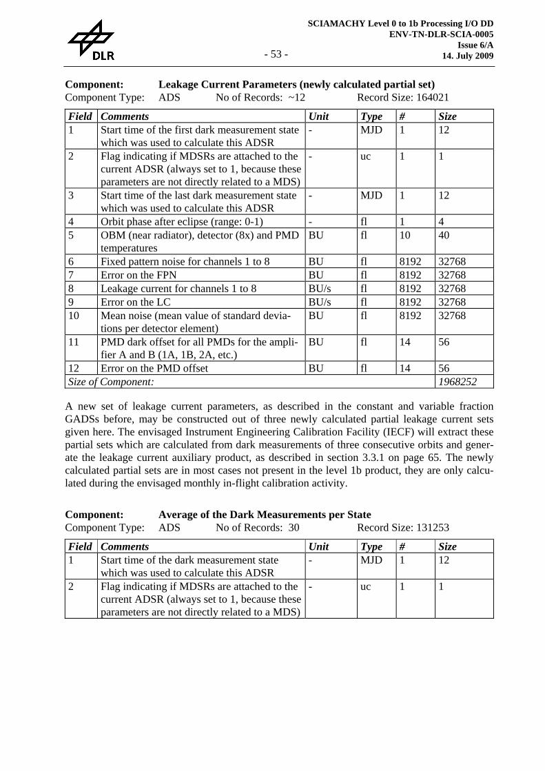
SCIAMACHY Level 0 to 1b Processing I/O DD ENV-TN-DLR-SCIA-0005
Issue 6/A 14. July 2009 - 53 -
Component: Leakage Current Parameters (newly calculated partial set) Component Type: ADS No of Records: ~12 Record Size: 164021 Field Comments Unit Type # Size 1 Start time of the first dark measurement state
which was used to calculate this ADSR - MJD 1 12
2 Flag indicating if MDSRs are attached to the current ADSR (always set to 1, because these parameters are not directly related to a MDS)
- uc 1 1
3 Start time of the last dark measurement state which was used to calculate this ADSR
- MJD 1 12
4 Orbit phase after eclipse (range: 0-1) - fl 1 4 5 OBM (near radiator), detector (8x) and PMD
temperatures BU fl 10 40
6 Fixed pattern noise for channels 1 to 8 BU fl 8192 32768 7 Error on the FPN BU fl 8192 32768 8 Leakage current for channels 1 to 8 BU/s fl 8192 32768 9 Error on the LC BU/s fl 8192 32768 10 Mean noise (mean value of standard devia-
tions per detector element) BU fl 8192 32768
11 PMD dark offset for all PMDs for the ampli-fier A and B (1A, 1B, 2A, etc.)
BU fl 14 56
12 Error on the PMD offset BU fl 14 56 Size of Component: 1968252
A new set of leakage current parameters, as described in the constant and variable fraction GADSs before, may be constructed out of three newly calculated partial leakage current sets given here. The envisaged Instrument Engineering Calibration Facility (IECF) will extract these partial sets which are calculated from dark measurements of three consecutive orbits and gener-ate the leakage current auxiliary product, as described in section 3.3.1 on page 65. The newly calculated partial sets are in most cases not present in the level 1b product, they are only calcu-lated during the envisaged monthly in-flight calibration activity.
Component: Average of the Dark Measurements per State Component Type: ADS No of Records: 30 Record Size: 131253 Field Comments Unit Type # Size 1 Start time of the dark measurement state
which was used to calculate this ADSR - MJD 1 12
2 Flag indicating if MDSRs are attached to the current ADSR (always set to 1, because these parameters are not directly related to a MDS)
- uc 1 1
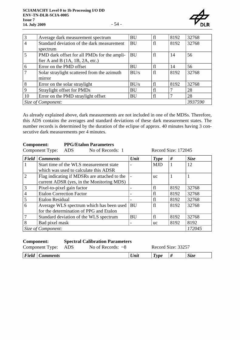
SCIAMACHY Level 0 to 1b Processing I/O DD ENV-TN-DLR-SCIA-0005 Issue 7 14. July 2009 - 54 -
3 Average dark measurement spectrum BU fl 8192 32768 4 Standard deviation of the dark measurement
spectrum BU fl 8192 32768
5 PMD dark offset for all PMDs for the ampli-fier A and B (1A, 1B, 2A, etc.)
BU fl 14 56
6 Error on the PMD offset BU fl 14 56 7 Solar straylight scattered from the azimuth
mirror BU/s fl 8192 32768
8 Error on the solar straylight BU/s fl 8192 32768 9 Straylight offset for PMDs BU fl 7 28 10 Error on the PMD straylight offset BU fl 7 28 Size of Component: 3937590
As already explained above, dark measurements are not included in one of the MDSs. Therefore, this ADS contains the averages and standard deviations of these dark measurement states. The number records is determined by the duration of the eclipse of approx. 40 minutes having 3 con-secutive dark measurements per 4 minutes.
Component: PPG/Etalon Parameters Component Type: ADS No of Records: 1 Record Size: 172045 Field Comments Unit Type # Size 1 Start time of the WLS measurement state
which was used to calculate this ADSR - MJD 1 12
2 Flag indicating if MDSRs are attached to the current ADSR (yes, in the Monitoring MDS)
- uc 1 1
3 Pixel-to-pixel gain factor - fl 8192 32768 4 Etalon Correction Factor - fl 8192 32768 5 Etalon Residual - fl 8192 32768 6 Average WLS spectrum which has been used
for the determination of PPG and Etalon BU fl 8192 32768
7 Standard deviation of the WLS spectrum BU fl 8192 32768 8 Bad pixel mask - uc 8192 8192 Size of Component: 172045
Component: Spectral Calibration Parameters Component Type: ADS No of Records: ~8 Record Size: 33257 Field Comments Unit Type # Size
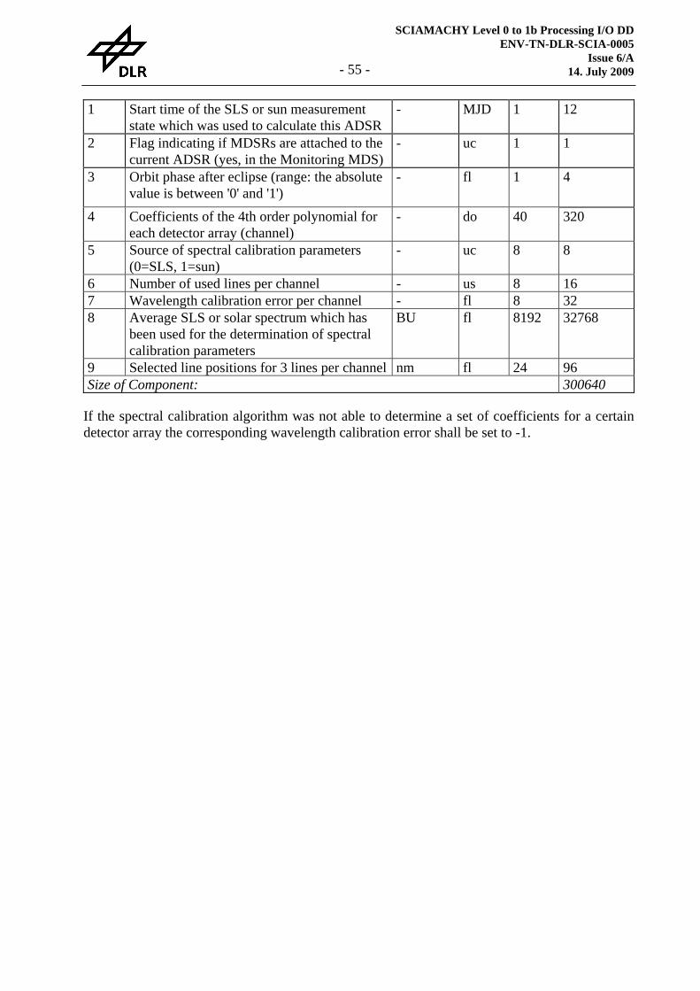
SCIAMACHY Level 0 to 1b Processing I/O DD ENV-TN-DLR-SCIA-0005
Issue 6/A 14. July 2009 - 55 -
1 Start time of the SLS or sun measurement state which was used to calculate this ADSR
- MJD 1 12
2 Flag indicating if MDSRs are attached to the current ADSR (yes, in the Monitoring MDS)
- uc 1 1
3 Orbit phase after eclipse (range: the absolute value is between '0' and '1')
- fl 1 4
4 Coefficients of the 4th order polynomial for each detector array (channel)
- do 40 320
5 Source of spectral calibration parameters (0=SLS, 1=sun)
- uc 8 8
6 Number of used lines per channel - us 8 16 7 Wavelength calibration error per channel - fl 8 32 8 Average SLS or solar spectrum which has
been used for the determination of spectral calibration parameters
BU fl 8192 32768
9 Selected line positions for 3 lines per channel nm fl 24 96 Size of Component: 300640
If the spectral calibration algorithm was not able to determine a set of coefficients for a certain detector array the corresponding wavelength calibration error shall be set to -1.
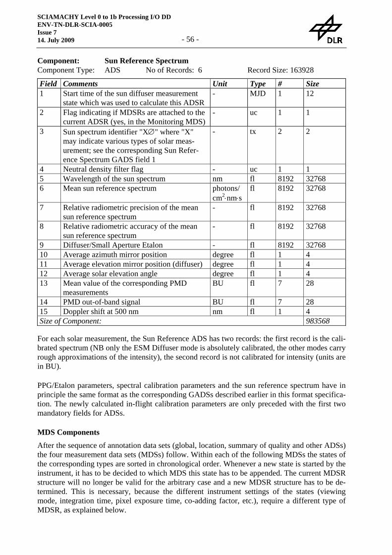
SCIAMACHY Level 0 to 1b Processing I/O DD ENV-TN-DLR-SCIA-0005 Issue 7 14. July 2009 - 56 -
Component: Sun Reference Spectrum Component Type: ADS No of Records: 6 Record Size: 163928 Field Comments Unit Type # Size 1 Start time of the sun diffuser measurement
state which was used to calculate this ADSR - MJD 1 12
2 Flag indicating if MDSRs are attached to the current ADSR (yes, in the Monitoring MDS)
- uc 1 1
3 Sun spectrum identifier "X∅" where "X" may indicate various types of solar meas-urement; see the corresponding Sun Refer-ence Spectrum GADS field 1
- tx 2 2
4 Neutral density filter flag - uc 1 1 5 Wavelength of the sun spectrum nm fl 8192 32768 6 Mean sun reference spectrum photons/
cm2⋅nm⋅s fl 8192 32768
7 Relative radiometric precision of the mean sun reference spectrum
- fl 8192 32768
8 Relative radiometric accuracy of the mean sun reference spectrum
- fl 8192 32768
9 Diffuser/Small Aperture Etalon - fl 8192 32768 10 Average azimuth mirror position degree fl 1 4 11 Average elevation mirror position (diffuser) degree fl 1 4 12 Average solar elevation angle degree fl 1 4 13 Mean value of the corresponding PMD
measurements BU fl 7 28
14 PMD out-of-band signal BU fl 7 28 15 Doppler shift at 500 nm nm fl 1 4 Size of Component: 983568
For each solar measurement, the Sun Reference ADS has two records: the first record is the cali-brated spectrum (NB only the ESM Diffuser mode is absolutely calibrated, the other modes carry rough approximations of the intensity), the second record is not calibrated for intensity (units are in BU).
PPG/Etalon parameters, spectral calibration parameters and the sun reference spectrum have in principle the same format as the corresponding GADSs described earlier in this format specifica-tion. The newly calculated in-flight calibration parameters are only preceded with the first two mandatory fields for ADSs.
MDS Components
After the sequence of annotation data sets (global, location, summary of quality and other ADSs) the four measurement data sets (MDSs) follow. Within each of the following MDSs the states of the corresponding types are sorted in chronological order. Whenever a new state is started by the instrument, it has to be decided to which MDS this state has to be appended. The current MDSR structure will no longer be valid for the arbitrary case and a new MDSR structure has to be de-termined. This is necessary, because the different instrument settings of the states (viewing mode, integration time, pixel exposure time, co-adding factor, etc.), require a different type of MDSR, as explained below.
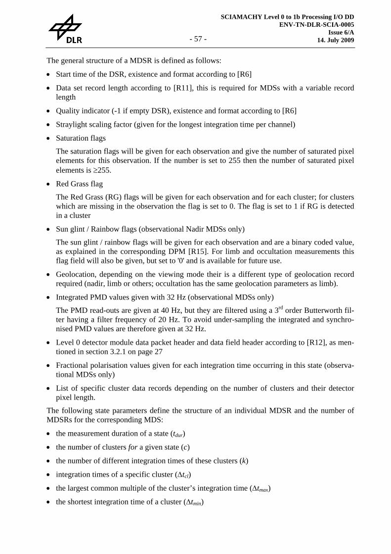
SCIAMACHY Level 0 to 1b Processing I/O DD ENV-TN-DLR-SCIA-0005
Issue 6/A 14. July 2009 - 57 -
The general structure of a MDSR is defined as follows:
• Start time of the DSR, existence and format according to [R6]
• Data set record length according to [R11], this is required for MDSs with a variable record length
• Quality indicator (-1 if empty DSR), existence and format according to [R6]
• Straylight scaling factor (given for the longest integration time per channel)
• Saturation flags
The saturation flags will be given for each observation and give the number of saturated pixel elements for this observation. If the number is set to 255 then the number of saturated pixel elements is ≥255.
• Red Grass flag
The Red Grass (RG) flags will be given for each observation and for each cluster; for clusters which are missing in the observation the flag is set to 0. The flag is set to 1 if RG is detected in a cluster
• Sun glint / Rainbow flags (observational Nadir MDSs only)
The sun glint / rainbow flags will be given for each observation and are a binary coded value, as explained in the corresponding DPM [R15]. For limb and occultation measurements this flag field will also be given, but set to '0' and is available for future use.
• Geolocation, depending on the viewing mode their is a different type of geolocation record required (nadir, limb or others; occultation has the same geolocation parameters as limb).
• Integrated PMD values given with 32 Hz (observational MDSs only)
The PMD read-outs are given at 40 Hz, but they are filtered using a 3rd order Butterworth fil-ter having a filter frequency of 20 Hz. To avoid under-sampling the integrated and synchro-nised PMD values are therefore given at 32 Hz.
• Level 0 detector module data packet header and data field header according to [R12], as men-tioned in section 3.2.1 on page 27
• Fractional polarisation values given for each integration time occurring in this state (observa-tional MDSs only)
• List of specific cluster data records depending on the number of clusters and their detector pixel length.
The following state parameters define the structure of an individual MDSR and the number of MDSRs for the corresponding MDS:
• the measurement duration of a state (tdur)
• the number of clusters for a given state (c)
• the number of different integration times of these clusters (k)
• integration times of a specific cluster (Δtcl)
• the largest common multiple of the cluster’s integration time (Δtmax)
• the shortest integration time of a cluster (Δtmin)

SCIAMACHY Level 0 to 1b Processing I/O DD ENV-TN-DLR-SCIA-0005 Issue 7 14. July 2009 - 58 -
for all clusters: Δ Δ Δt t tmax cl min≥ ≥
• the number of detector pixels per cluster (ncl)
To calculate the structural parameters of a certain MDS, the following formulas have to applied:
• number of MDSRs (Nrec)
N ttrecdur
max
=Δ
For Limb measurements there is a special situation due to the measurement gap of 3 BCPSs between each azimuth scan. Therefore, the division of the measurement duration by the long-est integration time makes no sense and the number of MDSRs for Limb is fixed to 35 con-sisting of 34 azimuth scan having an integration time of 1.5 seconds and an attached dark measurement by looking into deep space for the last MDSR.1
• number of repetitions for the auxiliary information (saturation flags, geolocation, and level 0 detector data packet header, Naux; the integrated PMD values are given always for half of the smallest possible integration time of 31.25 ms, NIntPMD)
ms25.31max
IntPMDmin
maxaux
tNttN Δ
=ΔΔ
=
• number of repetitions for cluster record of cluster i (Ncl,i)
N ttcl imax
cl i,
,
=ΔΔ
The fractional polarisation values will be given for each integration time which occurs (k times)
• length of a MDSR − for observational measurements
∑∑==
⋅+⋅+⋅⋅+⋅+=c
iiclicl
k
jpoljclPMDIntPMDauxauxheadrec nNLNnNLNLL
1,,
1, )()()4()(
− for monitoring measurements
L L N L N nrec head aux aux cl i cl ii
c
= + ⋅ + ⋅=∑( ) ( ), ,
1
where:
The measurement duration of a Limb state is 59.0625 seconds. This may be calculated as follows: one azimuth scan has a net integration time of 1.5 seconds and the adjustment of the elevation mirror for the next azimuth scan takes 3 BCPSs corresponding to 0.1875 seconds giving a total of 1.6875 seconds for one azimuth scan. 34 azimuth scan plus one dark measurement into deep space (which takes the same time as one azimuth scan) gives a state du-ration of: 35 ⋅ 1.6875 s = 59.0625 s.

SCIAMACHY Level 0 to 1b Processing I/O DD ENV-TN-DLR-SCIA-0005
Issue 6/A 14. July 2009 - 59 -
− Lhead is the length of the constant header information of a MDSR including the quality flags (size = 120 for observational measurements; size = 17 for monitoring measurements)
− Laux is the length of the auxiliary information (size = 182 for observational measurements; size = 92 for monitoring measurements)
− nPMD is the number of PMDs (=7) − Lpol is the length of the fractional polarisation values compound data type
(PolV; size = 256) • length of a MDS
L N LMDS rec rec= ⋅
Note
The examples and the tables for MDS construction in this I/O DD are only given for illustration purpose. They are based on the present operational definitions given in [R4], but they are by no means fixed for the future. Therefore, software for reading of level 0 and writing of level 1b data have to be designed and implemented in a highly flexible way to identify the structure of states
and construct the appropriate MDSR accordingly
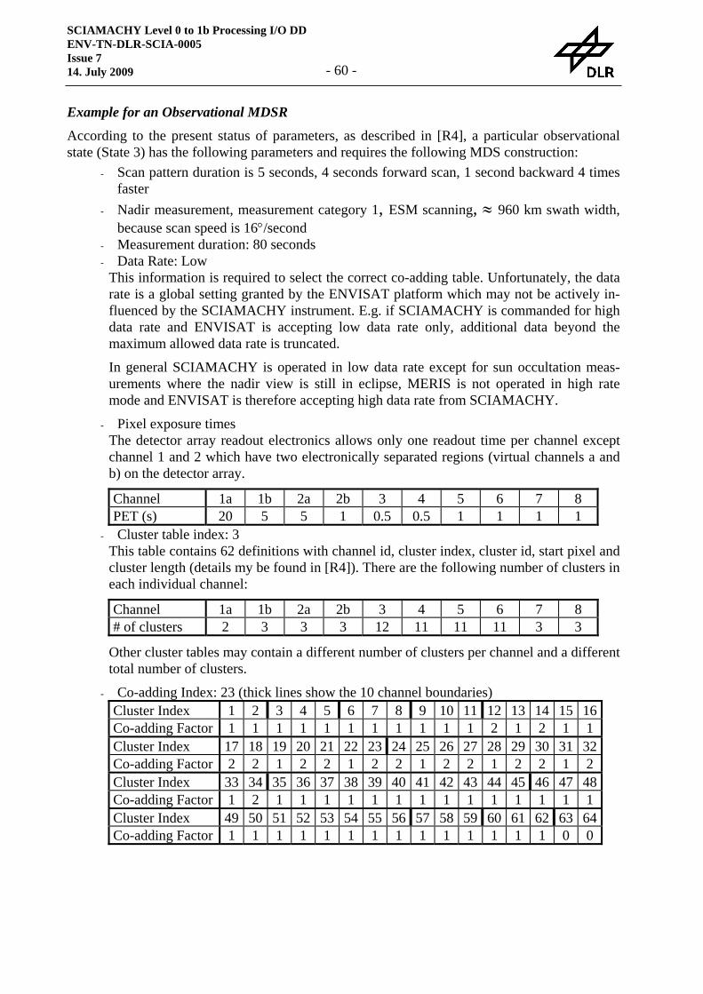
SCIAMACHY Level 0 to 1b Processing I/O DD ENV-TN-DLR-SCIA-0005 Issue 7 14. July 2009 - 60 -
Example for an Observational MDSR
According to the present status of parameters, as described in [R4], a particular observational state (State 3) has the following parameters and requires the following MDS construction:
- Scan pattern duration is 5 seconds, 4 seconds forward scan, 1 second backward 4 times faster
- Nadir measurement, measurement category 1, ESM scanning, ≈ 960 km swath width, because scan speed is 16°/second
- Measurement duration: 80 seconds - Data Rate: Low
This information is required to select the correct co-adding table. Unfortunately, the data rate is a global setting granted by the ENVISAT platform which may not be actively in-fluenced by the SCIAMACHY instrument. E.g. if SCIAMACHY is commanded for high data rate and ENVISAT is accepting low data rate only, additional data beyond the maximum allowed data rate is truncated.
In general SCIAMACHY is operated in low data rate except for sun occultation meas-urements where the nadir view is still in eclipse, MERIS is not operated in high rate mode and ENVISAT is therefore accepting high data rate from SCIAMACHY.
- Pixel exposure times The detector array readout electronics allows only one readout time per channel except channel 1 and 2 which have two electronically separated regions (virtual channels a and b) on the detector array.
Channel 1a 1b 2a 2b 3 4 5 6 7 8 PET (s) 20 5 5 1 0.5 0.5 1 1 1 1
- Cluster table index: 3 This table contains 62 definitions with channel id, cluster index, cluster id, start pixel and cluster length (details my be found in [R4]). There are the following number of clusters in each individual channel: Channel 1a 1b 2a 2b 3 4 5 6 7 8 # of clusters 2 3 3 3 12 11 11 11 3 3
Other cluster tables may contain a different number of clusters per channel and a different total number of clusters.
- Co-adding Index: 23 (thick lines show the 10 channel boundaries) Cluster Index 1 2 3 4 5 6 7 8 9 10 11 12 13 14 15 16Co-adding Factor 1 1 1 1 1 1 1 1 1 1 1 2 1 2 1 1 Cluster Index 17 18 19 20 21 22 23 24 25 26 27 28 29 30 31 32Co-adding Factor 2 2 1 2 2 1 2 2 1 2 2 1 2 2 1 2 Cluster Index 33 34 35 36 37 38 39 40 41 42 43 44 45 46 47 48Co-adding Factor 1 2 1 1 1 1 1 1 1 1 1 1 1 1 1 1 Cluster Index 49 50 51 52 53 54 55 56 57 58 59 60 61 62 63 64Co-adding Factor 1 1 1 1 1 1 1 1 1 1 1 1 1 1 0 0
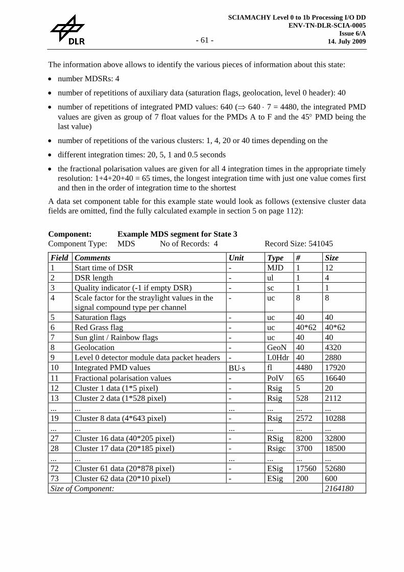
SCIAMACHY Level 0 to 1b Processing I/O DD ENV-TN-DLR-SCIA-0005
Issue 6/A 14. July 2009 - 61 -
The information above allows to identify the various pieces of information about this state:
• number MDSRs: 4
• number of repetitions of auxiliary data (saturation flags, geolocation, level 0 header): 40
• number of repetitions of integrated PMD values: 640 (⇒ 640 ⋅ 7 = 4480, the integrated PMD values are given as group of 7 float values for the PMDs A to F and the 45° PMD being the last value)
• number of repetitions of the various clusters: 1, 4, 20 or 40 times depending on the
• different integration times: 20, 5, 1 and 0.5 seconds
• the fractional polarisation values are given for all 4 integration times in the appropriate timely resolution: 1+4+20+40 = 65 times, the longest integration time with just one value comes first and then in the order of integration time to the shortest
A data set component table for this example state would look as follows (extensive cluster data fields are omitted, find the fully calculated example in section 5 on page 112):
Component: Example MDS segment for State 3 Component Type: MDS No of Records: 4 Record Size: 541045 Field Comments Unit Type # Size 1 Start time of DSR - MJD 1 12 2 DSR length - ul 1 4 3 Quality indicator (-1 if empty DSR) - sc 1 1 4 Scale factor for the straylight values in the
signal compound type per channel - uc 8 8
5 Saturation flags - uc 40 40 6 Red Grass flag - uc 40*62 40*62 7 Sun glint / Rainbow flags - uc 40 40 8 Geolocation - GeoN 40 4320 9 Level 0 detector module data packet headers - L0Hdr 40 2880 10 Integrated PMD values BU⋅s fl 4480 17920 11 Fractional polarisation values - PolV 65 16640 12 Cluster 1 data (1*5 pixel) - Rsig 5 20 13 Cluster 2 data (1*528 pixel) - Rsig 528 2112 ... ... ... ... ... ... 19 Cluster 8 data (4*643 pixel) - Rsig 2572 10288 ... ... ... ... ... ... 27 Cluster 16 data (40*205 pixel) - RSig 8200 32800 28 Cluster 17 data (20*185 pixel) - Rsigc 3700 18500 ... ... ... ... ... ... 72 Cluster 61 data (20*878 pixel) - ESig 17560 52680 73 Cluster 62 data (20*10 pixel) - ESig 200 600 Size of Component: 2164180

SCIAMACHY Level 0 to 1b Processing I/O DD ENV-TN-DLR-SCIA-0005 Issue 7 14. July 2009 - 62 -
Example for a Monitoring MDSR
According to the present status of parameters, as described in [R4], a particular monitoring state (State 53) has the following parameters and requires the following MDS construction:
- No scanning for this state - Sub-solar calibration pointing measurement, measurement category 9 - Measurement duration: 21 seconds - Data Rate: Low - Pixel exposure times
The detector array readout electronics allows only one readout time per channel except channel 1 and 2 which have two electronically separated regions (virtual channels a and b) on the detector array. Channel 6 and 7 are readout using the 'hot' mode, this means that
Channel 1a 1b 2a 2b 3 4 5 6 7 8 PET (s) 1/8
1/8 1/16 1/16 1/16 1/16 1/16 1/32 1/32 1/16 - Cluster table index: 1
This table contains 26 definitions with channel id, cluster index, cluster id, start pixel and cluster length (details my be found in [R4]). There are the following number of clusters in each individual channel: Channel 1a 1b 2a 2b 3 4 5 6 7 8 # of clusters 2 2 2 2 3 3 3 3 3 3
Other cluster tables may contain a different number of clusters per channel and a different total number of clusters.
- Co-adding Index: 31 (thick lines show the 10 channel boundaries) Cluster Index 1 2 3 4 5 6 7 8 9 10 11 12 13 14 15 16Co-adding Factor 4 4 4 4 8 8 8 8 8 8 8 8 8 8 8 8 Cluster Index 17 18 19 20 21 22 23 24 25 26 27 28 29 30 31 32Co-adding Factor 8 8 8 8 8 8 8 8 8 8 0 0 0 0 0 0 Cluster Index 33 34 35 36 37 38 39 40 41 42 43 44 45 46 47 48Co-adding Factor 0 0 0 0 0 0 0 0 0 0 0 0 0 0 0 0 Cluster Index 49 50 51 52 53 54 55 56 57 58 59 60 61 62 63 64Co-adding Factor 0 0 0 0 0 0 0 0 0 0 0 0 0 0 0 0
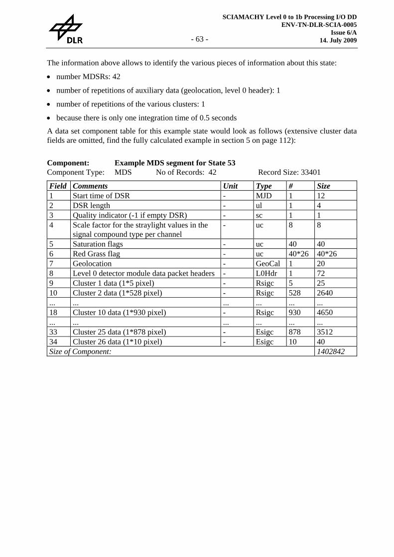
SCIAMACHY Level 0 to 1b Processing I/O DD ENV-TN-DLR-SCIA-0005
Issue 6/A 14. July 2009 - 63 -
The information above allows to identify the various pieces of information about this state:
• number MDSRs: 42
• number of repetitions of auxiliary data (geolocation, level 0 header): 1
• number of repetitions of the various clusters: 1
• because there is only one integration time of 0.5 seconds
A data set component table for this example state would look as follows (extensive cluster data fields are omitted, find the fully calculated example in section 5 on page 112):
Component: Example MDS segment for State 53 Component Type: MDS No of Records: 42 Record Size: 33401 Field Comments Unit Type # Size 1 Start time of DSR - MJD 1 12 2 DSR length - ul 1 4 3 Quality indicator (-1 if empty DSR) - sc 1 1 4 Scale factor for the straylight values in the
signal compound type per channel - uc 8 8
5 Saturation flags - uc 40 40 6 Red Grass flag - uc 40*26 40*26 7 Geolocation - GeoCal 1 20 8 Level 0 detector module data packet headers - L0Hdr 1 72 9 Cluster 1 data (1*5 pixel) - Rsigc 5 25 10 Cluster 2 data (1*528 pixel) - Rsigc 528 2640 ... ... ... ... ... ... 18 Cluster 10 data (1*930 pixel) - Rsigc 930 4650 ... ... ... ... ... ... 33 Cluster 25 data (1*878 pixel) - Esigc 878 3512 34 Cluster 26 data (1*10 pixel) - Esigc 10 40 Size of Component: 1402842
SCIAMACHY Level 0 to 1b Processing I/O DD ENV-TN-DLR-SCIA-0005 Issue 7 14. July 2009 - 64 -
Sizing
The granule of a level 1b product is determined by the consolidation status and size of the level 0 product on input.
Only complete states will be processed. This means that ISPs which are not belonging to a com-plete state at the beginning or the end of a level 0 product will be skipped. Consolidation proc-essing has to take care of the state boundaries to ensure that no data is lost.
Data Volume
According to the example in section 5 on page 109 approx. 186 MB/orbit are expected. If the sun diffuser measurement in this example is replaced by a sun occultation measurement operated in high data rate the data volume of a level 1b product is expected to be extended to approx. 205 MB/orbit.
Throughput
SCIAMACHY is intended for continuous measuring. This implies approximately 14 orbits and the same number of level 1b products per day.
Remarks
General Structure of Calibration Parameters
Calibration parameters are in general given for all eight detector arrays, if not otherwise noted. Each detector array has 1024 detector elements which are kept together and are recorded from 0 to 1023 (0 corresponds to the lowest and 1023 to the highest wavelength in the corresponding channel) and the arrays are recorded from 1 to 8 which gives a total of 8192 consecutive values.
Reversed read-out order of channel 22
The reversed read-out order of channel 2 is not affecting the data format of the level 1b product. Similar to all other channels the detector pixel readouts are given in ascending wavelength order. It is just a timing issue at which precise time the individual pixels of channel 2 have been read out. This means that the last pixel of channel 1 is read out at the same time as the first pixel of channel 2 and the last pixel of channel 2 is read out at the same time as the first pixel of channel 3. This may be used to gain the over-lapping regions between channel 1 and 2 and between chan-nel 2 and 3 to retrieve a fractional polarisation value for these wavelength ranges which in gen-eral would suffer from an spatial aliasing effect due to the finite read-out time of all detector pixel of an array.
2 This note is only interesting for those who know about this reversed read-out order and are wondering whether it is influencing the level 1b data format. In level 0 data the cluster configuration information and cluster data itself from channel 2 are given in reversed order. SGP_01 takes care of re-ordering to provide all clusters in ascending wavelength order.
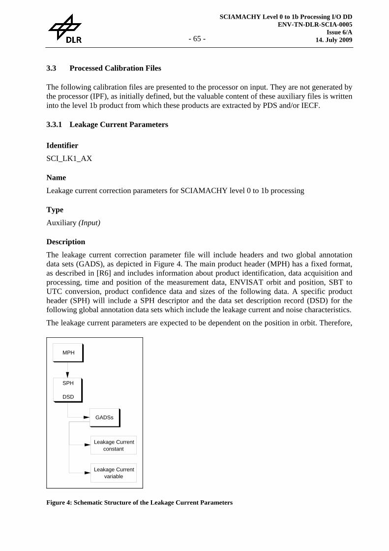
SCIAMACHY Level 0 to 1b Processing I/O DD ENV-TN-DLR-SCIA-0005
Issue 6/A 14. July 2009 - 65 -
3.3 Processed Calibration Files
The following calibration files are presented to the processor on input. They are not generated by the processor (IPF), as initially defined, but the valuable content of these auxiliary files is written into the level 1b product from which these products are extracted by PDS and/or IECF.
3.3.1 Leakage Current Parameters
Identifier
SCI_LK1_AX
Name
Leakage current correction parameters for SCIAMACHY level 0 to 1b processing
Type
Auxiliary (Input)
Description
The leakage current correction parameter file will include headers and two global annotation data sets (GADS), as depicted in Figure 4. The main product header (MPH) has a fixed format, as described in [R6] and includes information about product identification, data acquisition and processing, time and position of the measurement data, ENVISAT orbit and position, SBT to UTC conversion, product confidence data and sizes of the following data. A specific product header (SPH) will include a SPH descriptor and the data set description record (DSD) for the following global annotation data sets which include the leakage current and noise characteristics.
The leakage current parameters are expected to be dependent on the position in orbit. Therefore,
MPH
SPH
DSD
GADSs
Leakage Currentconstant
Leakage Currentvariable
Figure 4: Schematic Structure of the Leakage Current Parameters
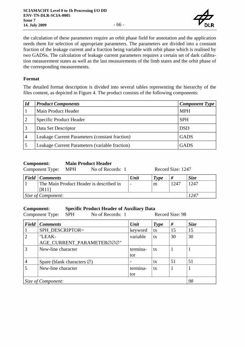
SCIAMACHY Level 0 to 1b Processing I/O DD ENV-TN-DLR-SCIA-0005 Issue 7 14. July 2009 - 66 -
the calculation of these parameters require an orbit phase field for annotation and the application needs them for selection of appropriate parameters. The parameters are divided into a constant fraction of the leakage current and a fraction being variable with orbit phase which is realised by two GADSs. The calculation of leakage current parameters requires a certain set of dark calibra-tion measurement states as well as the last measurements of the limb states and the orbit phase of the corresponding measurements.
Format
The detailed format description is divided into several tables representing the hierarchy of the files content, as depicted in Figure 4. The product consists of the following components:
Id Product Components Component Type1 Main Product Header MPH
2 Specific Product Header SPH
3 Data Set Descriptor DSD
4 Leakage Current Parameters (constant fraction) GADS
5 Leakage Current Parameters (variable fraction) GADS
Component: Main Product Header Component Type: MPH No of Records: 1 Record Size: 1247 Field Comments Unit Type # Size 1 The Main Product Header is described in
[R11] - m 1247 1247
Size of Component: 1247
Component: Specific Product Header of Auxiliary Data Component Type: SPH No of Records: 1 Record Size: 98 Field Comments Unit Type # Size 1 SPH_DESCRIPTOR= keyword tx 15 15 2 "LEAK-
AGE_CURRENT_PARAMETER∅∅∅" variable tx 30 30
3 New-line character termina-tor
tx 1 1
4 Spare (blank characters ∅) - tx 51 51 5 New-line character termina-
tor tx 1 1
Size of Component: 98

SCIAMACHY Level 0 to 1b Processing I/O DD ENV-TN-DLR-SCIA-0005
Issue 6/A 14. July 2009 - 67 -
Component: Data Set Descriptor Record Component Type: DSD No of Records: 2 Record Size: 280 Field Comments Unit Type # Size 1 Data Set Descriptor Record, as described in
[R11] - m 280 280
Size of Component: 560
For the data set name definitions please refer to the corresponding GADSs in the level 1b prod-uct.
Component: Leakage Current Parameters (constant fraction) Component Type: GADS No of Records: 1
This is a copy of the corresponding GADS on the Level 1b product
Component: Leakage Current Parameters (variable fraction) Component Type: GADS No of Records: 12
This is a copy of the corresponding GADS on the Level 1b product
Sizing
One complete set of leakage current parameters are covered by this file.
Data Volume
The leakage current parameter file requires approximately 1.2 MB.
Throughput
The eclipse side of the orbit will most of the time be used for dark measurements and the opti-mised nadir/limb scanning strategy on the illuminated side of the Earth provides enough addi-tional limb data measurements into deep space to calculate a complete set of leakage current parameters every orbit. Nevertheless, this is much to often and most of this data will be dis-carded. Approximately one leakage current parameter set per week is envisaged.
Remarks
See the corresponding remark concerning the leakage current components of this product in the description of the level 1b product (section 3.2.2).
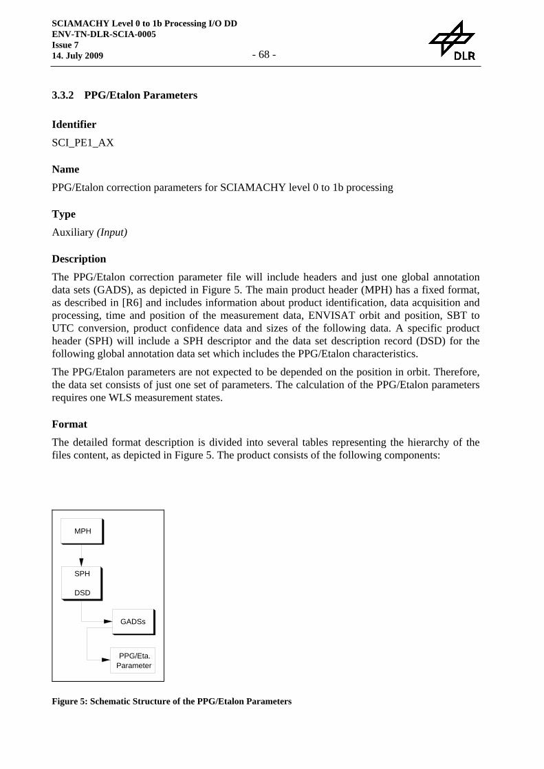
SCIAMACHY Level 0 to 1b Processing I/O DD ENV-TN-DLR-SCIA-0005 Issue 7 14. July 2009 - 68 -
3.3.2 PPG/Etalon Parameters
Identifier
SCI_PE1_AX
Name
PPG/Etalon correction parameters for SCIAMACHY level 0 to 1b processing
Type
Auxiliary (Input)
Description
The PPG/Etalon correction parameter file will include headers and just one global annotation data sets (GADS), as depicted in Figure 5. The main product header (MPH) has a fixed format, as described in [R6] and includes information about product identification, data acquisition and processing, time and position of the measurement data, ENVISAT orbit and position, SBT to UTC conversion, product confidence data and sizes of the following data. A specific product header (SPH) will include a SPH descriptor and the data set description record (DSD) for the following global annotation data set which includes the PPG/Etalon characteristics.
The PPG/Etalon parameters are not expected to be depended on the position in orbit. Therefore, the data set consists of just one set of parameters. The calculation of the PPG/Etalon parameters requires one WLS measurement states.
Format
The detailed format description is divided into several tables representing the hierarchy of the files content, as depicted in Figure 5. The product consists of the following components:
MPH
SPH
DSD
GADSs
PPG/Eta.Parameter
Figure 5: Schematic Structure of the PPG/Etalon Parameters
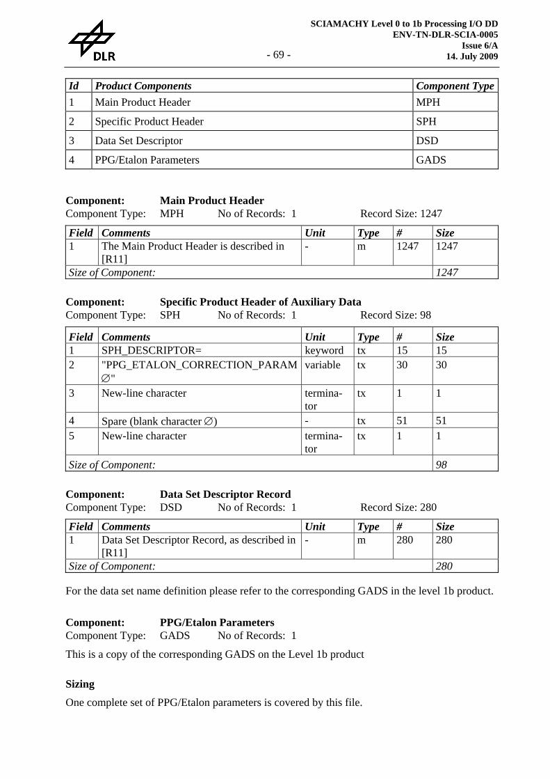
SCIAMACHY Level 0 to 1b Processing I/O DD ENV-TN-DLR-SCIA-0005
Issue 6/A 14. July 2009 - 69 -
Id Product Components Component Type1 Main Product Header MPH
2 Specific Product Header SPH
3 Data Set Descriptor DSD
4 PPG/Etalon Parameters GADS
Component: Main Product Header Component Type: MPH No of Records: 1 Record Size: 1247 Field Comments Unit Type # Size 1 The Main Product Header is described in
[R11] - m 1247 1247
Size of Component: 1247
Component: Specific Product Header of Auxiliary Data Component Type: SPH No of Records: 1 Record Size: 98 Field Comments Unit Type # Size 1 SPH_DESCRIPTOR= keyword tx 15 15 2 "PPG_ETALON_CORRECTION_PARAM
∅" variable tx 30 30
3 New-line character termina-tor
tx 1 1
4 Spare (blank character ∅) - tx 51 51 5 New-line character termina-
tor tx 1 1
Size of Component: 98
Component: Data Set Descriptor Record Component Type: DSD No of Records: 1 Record Size: 280 Field Comments Unit Type # Size 1 Data Set Descriptor Record, as described in
[R11] - m 280 280
Size of Component: 280
For the data set name definition please refer to the corresponding GADS in the level 1b product.
Component: PPG/Etalon Parameters Component Type: GADS No of Records: 1
This is a copy of the corresponding GADS on the Level 1b product
Sizing
One complete set of PPG/Etalon parameters is covered by this file.

SCIAMACHY Level 0 to 1b Processing I/O DD ENV-TN-DLR-SCIA-0005 Issue 7 14. July 2009 - 70 -
Data Volume
The PPG/Etalon parameter file requires approximately 1.4 MB.
Throughput
WLS measurements are planned for the weekly calibration timeline. Therefore, a PPG/Etalon file is expected once per week.
Remarks
N/A
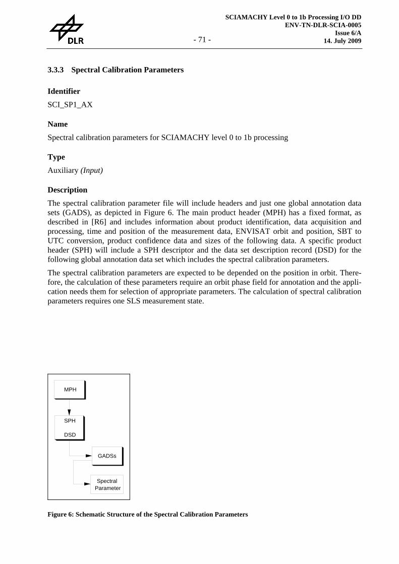
SCIAMACHY Level 0 to 1b Processing I/O DD ENV-TN-DLR-SCIA-0005
Issue 6/A 14. July 2009 - 71 -
3.3.3 Spectral Calibration Parameters
Identifier
SCI_SP1_AX
Name
Spectral calibration parameters for SCIAMACHY level 0 to 1b processing
Type
Auxiliary (Input)
Description
The spectral calibration parameter file will include headers and just one global annotation data sets (GADS), as depicted in Figure 6. The main product header (MPH) has a fixed format, as described in [R6] and includes information about product identification, data acquisition and processing, time and position of the measurement data, ENVISAT orbit and position, SBT to UTC conversion, product confidence data and sizes of the following data. A specific product header (SPH) will include a SPH descriptor and the data set description record (DSD) for the following global annotation data set which includes the spectral calibration parameters.
The spectral calibration parameters are expected to be depended on the position in orbit. There-fore, the calculation of these parameters require an orbit phase field for annotation and the appli-cation needs them for selection of appropriate parameters. The calculation of spectral calibration parameters requires one SLS measurement state.
MPH
SPH
DSD
GADSs
SpectralParameter
Figure 6: Schematic Structure of the Spectral Calibration Parameters
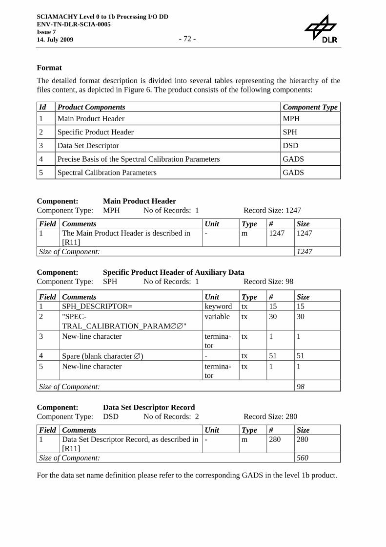
SCIAMACHY Level 0 to 1b Processing I/O DD ENV-TN-DLR-SCIA-0005 Issue 7 14. July 2009 - 72 -
Format
The detailed format description is divided into several tables representing the hierarchy of the files content, as depicted in Figure 6. The product consists of the following components:
Id Product Components Component Type1 Main Product Header MPH
2 Specific Product Header SPH
3 Data Set Descriptor DSD
4 Precise Basis of the Spectral Calibration Parameters GADS
5 Spectral Calibration Parameters GADS
Component: Main Product Header Component Type: MPH No of Records: 1 Record Size: 1247 Field Comments Unit Type # Size 1 The Main Product Header is described in
[R11] - m 1247 1247
Size of Component: 1247
Component: Specific Product Header of Auxiliary Data Component Type: SPH No of Records: 1 Record Size: 98 Field Comments Unit Type # Size 1 SPH_DESCRIPTOR= keyword tx 15 15 2 "SPEC-
TRAL_CALIBRATION_PARAM∅∅" variable tx 30 30
3 New-line character termina-tor
tx 1 1
4 Spare (blank character ∅) - tx 51 51 5 New-line character termina-
tor tx 1 1
Size of Component: 98
Component: Data Set Descriptor Record Component Type: DSD No of Records: 2 Record Size: 280 Field Comments Unit Type # Size 1 Data Set Descriptor Record, as described in
[R11] - m 280 280
Size of Component: 560
For the data set name definition please refer to the corresponding GADS in the level 1b product.
SCIAMACHY Level 0 to 1b Processing I/O DD ENV-TN-DLR-SCIA-0005
Issue 6/A 14. July 2009 - 73 -
Component: Precise Basis of the Spectral Calibration Parameters Component Type: GADS No of Records: 1
This is a copy of the corresponding GADS on the Level 1b product
Component: Spectral Calibration Parameters Component Type: GADS No of Records: 12
This is a copy of the corresponding GADS on the Level 1b product
Sizing
One complete set of spectral calibration parameters are covered by this file.
Data Volume
The spectral calibration parameter file requires approximately 38 kB.
Throughput
SLS measurements are planned for the weekly calibration timeline. Therefore, a spectral calibra-tion file is expected once per week.
Remarks
N/A
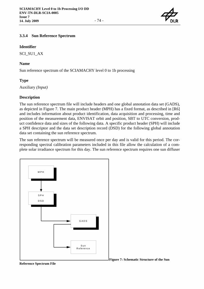
SCIAMACHY Level 0 to 1b Processing I/O DD ENV-TN-DLR-SCIA-0005 Issue 7 14. July 2009 - 74 -
3.3.4 Sun Reference Spectrum
Identifier
SCI_SU1_AX
Name
Sun reference spectrum of the SCIAMACHY level 0 to 1b processing
Type
Auxiliary (Input)
Description
The sun reference spectrum file will include headers and one global annotation data set (GADS), as depicted in Figure 7. The main product header (MPH) has a fixed format, as described in [R6] and includes information about product identification, data acquisition and processing, time and position of the measurement data, ENVISAT orbit and position, SBT to UTC conversion, prod-uct confidence data and sizes of the following data. A specific product header (SPH) will include a SPH descriptor and the data set description record (DSD) for the following global annotation data set containing the sun reference spectrum.
The sun reference spectrum will be measured once per day and is valid for this period. The cor-responding spectral calibration parameters included in this file allow the calculation of a com-plete solar irradiance spectrum for this day. The sun reference spectrum requires one sun diffuser
M P H
S P H
D S D
G A D S
S u nR e fe re n c e
Figure 7: Schematic Structure of the Sun Reference Spectrum File
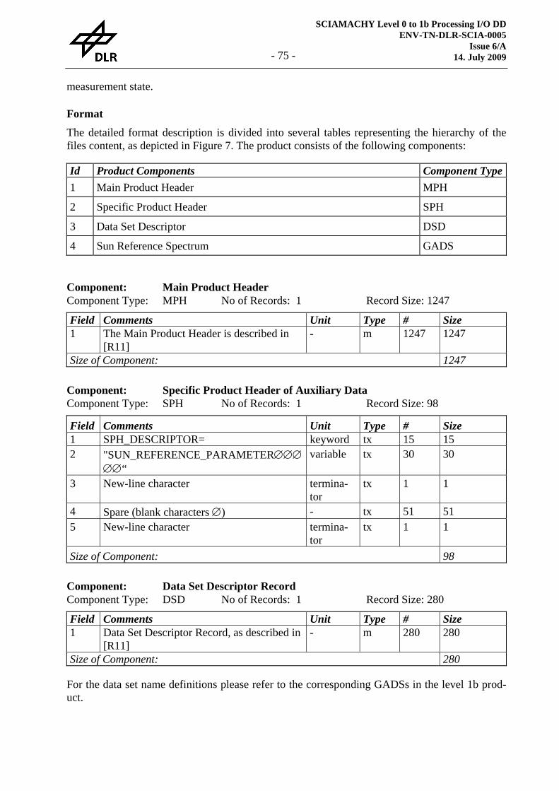
SCIAMACHY Level 0 to 1b Processing I/O DD ENV-TN-DLR-SCIA-0005
Issue 6/A 14. July 2009 - 75 -
measurement state.
Format
The detailed format description is divided into several tables representing the hierarchy of the files content, as depicted in Figure 7. The product consists of the following components:
Id Product Components Component Type1 Main Product Header MPH
2 Specific Product Header SPH
3 Data Set Descriptor DSD
4 Sun Reference Spectrum GADS
Component: Main Product Header Component Type: MPH No of Records: 1 Record Size: 1247 Field Comments Unit Type # Size 1 The Main Product Header is described in
[R11] - m 1247 1247
Size of Component: 1247
Component: Specific Product Header of Auxiliary Data Component Type: SPH No of Records: 1 Record Size: 98 Field Comments Unit Type # Size 1 SPH_DESCRIPTOR= keyword tx 15 15 2 "SUN_REFERENCE_PARAMETER∅∅∅
∅∅“ variable tx 30 30
3 New-line character termina-tor
tx 1 1
4 Spare (blank characters ∅) - tx 51 51 5 New-line character termina-
tor tx 1 1
Size of Component: 98
Component: Data Set Descriptor Record Component Type: DSD No of Records: 1 Record Size: 280 Field Comments Unit Type # Size 1 Data Set Descriptor Record, as described in
[R11] - m 280 280
Size of Component: 280
For the data set name definitions please refer to the corresponding GADSs in the level 1b prod-uct.
SCIAMACHY Level 0 to 1b Processing I/O DD ENV-TN-DLR-SCIA-0005 Issue 7 14. July 2009 - 76 -
Component: Sun Reference Spectrum Component Type: GADS No of Records: 1
This is a copy of the corresponding GADS on the Level 1b product
Sizing
One complete sun reference spectrum is covered by this file.
Data Volume
The sun reference spectrum parameter file requires approximately 165 kB.
Throughput
As explained before, it is expected to do one sun diffuser calibration per day which yields one sun reference spectrum file per day.
Remarks
See the corresponding remarks concerning the various components of this product in the descrip-tion of the level 1b product (section 3.2.2).
SCIAMACHY Level 0 to 1b Processing I/O DD ENV-TN-DLR-SCIA-0005
Issue 6/A 14. July 2009 - 77 -
3.4 Auxiliary Data Files
3.4.1 Initialisation File
Identifier
SCI_LI1_AX
Name
Initialisation file for a SCIAMACHY level 0 to 1b processor
Type
Auxiliary (Input)
Description
In principle static parameters may be inserted as constants directly into the processor’s code, but the use of an initialisation file improves the maintainability of SGP_01. The GADS of the ini-tialisation file for the static parameters is a simple ASCII list consisting of a number of keywords representing the static parameters of the level 0 to 1b processing followed by the values of these parameters. The position of the parameters in this list is arbitrary, but the structure of the pa-rameter values following a certain parameter's name has to be known by the code reading the static parameters.
Besides the static parameters the initialisation file includes also a set of three spectrum templates (gathered in a second GADS), a list of external instrument state parameters (the third GADS) which are not available through the ISPs of the instrument and the polarisation and radiance sen-sitivity grids (fourth GADS).
The initialisation file will include headers and three GADS. The main product header (MPH) has a fixed format, as described in [R11], and includes information about product identification and sizes of the following data. Other fields in the general MPH (such as data acquisition and proc-essing time, position of the measurement data, ENVISAT orbit and position, SBT to UTC con-version and product confidence data) have no real meaning for this product type and will be left blank. A specific product header (SPH) will include a SPH descriptor and the data set descrip-tion record (DSD) for the following GADSs. The GADSs of this initialisation file will have a single DSR described below.
SCIAMACHY Level 0 to 1b Processing I/O DD ENV-TN-DLR-SCIA-0005 Issue 7 14. July 2009 - 78 -
Format
The product consists of the following components:
Id Product Components Component Type1 Main Product Header MPH
2 Specific Product Header SPH
3 Data Set Descriptor DSD
4 Static Parameters GADS
5 Spectrum Templates GADS
6 External State Parameters GADS
7 Processing Categories GADS
8 Polarisation and Radiance Sensitivity Grids GADS
The following paragraphs describe the detailed definition of the components listed above:
Component: Main Product Header Component Type: MPH No of Records: 1 Record Size: 1247 Field Comments Unit Type # Size 1 The Main Product Header is described in
[R11] - m 1247 1247
Size of Component: 1247
Component: Specific Product Header of Auxiliary Data Component Type: SPH No of Records: 1 Record Size: 98 Field Comments Unit Type # Size 1 SPH_DESCRIPTOR= keyword tx 15 15 2 "INITIALISA-
TION_FILE∅∅∅∅∅∅∅∅∅" variable tx 30 30
3 New-line character termina-tor
tx 1 1
4 Spare (blank characters ∅) - tx 51 51 5 New-line character termina-
tor tx 1 1
Size of Component: 98
Component: Data Set Descriptor Record Component Type: DSD No of Records: 5 Record Size: 280 Field Comments Unit Type # Size 1 Data Set Descriptor Record, as described in
[R11] - m 280 280
Size of Component: 1400
SCIAMACHY Level 0 to 1b Processing I/O DD ENV-TN-DLR-SCIA-0005
Issue 6/A 14. July 2009 - 79 -
The DS_NAME field of the DSDs will be set according to the content of the corresponding GADS. The following keywords are used:
1. Static Parameters
2. Spectrum Templates
3. External State Parameters
4. Processing Categories
5. Pol. and Rad. Sens. Grids
Component: Static Parameter Component Type: GADS No of Records: 1
The following GADS record is an ASCII list of parameters not defined by their precise position in the file, but by keywords for each parameter. Initialisation parameter inputs are either logical control flags, real or integer numbers, or names (key-word or key-words). Each ‘name’ input is one of a small group of possible name options. ... Parameter-Keyword Parameter-Value(s) ...
Lines preceded by an exclamation mark ‘!’ or not starting in the first column are handled as comments. The following conventions shall be adopted for parameter input:
• logical parameters values shall be given as ‘t’ or ‘f’;
• numerical parameter values shall follow the syntax for numerical constants in the C pro-gramming language;
• all possible choices of name parameter values shall be described.
The detailed list of parameters is given in the corresponding DPM [R15].
The size of this component was fixed to a new size of 20 kB. This is approximately 25% more than the actually size of this component today (15060 Bytes on 2.9.2005) leaving enough space for future changes. The empty space at the end of the static parameters is filled with blanks until the end of the component.
Component: Spectrum Templates Component Type: GADS No of Records: 1 Record Size: 131072 Field Comments Unit Type # Size 1 Wavelength nm fl 8192 32768 2 External sun reference spectrum - fl 8192 32768 3 Template earth-shine spectrum - fl 8192 32768 4 External PPG reference spectrum (for Key-
Data) - fl 8192 32768
Size of Component: 131072
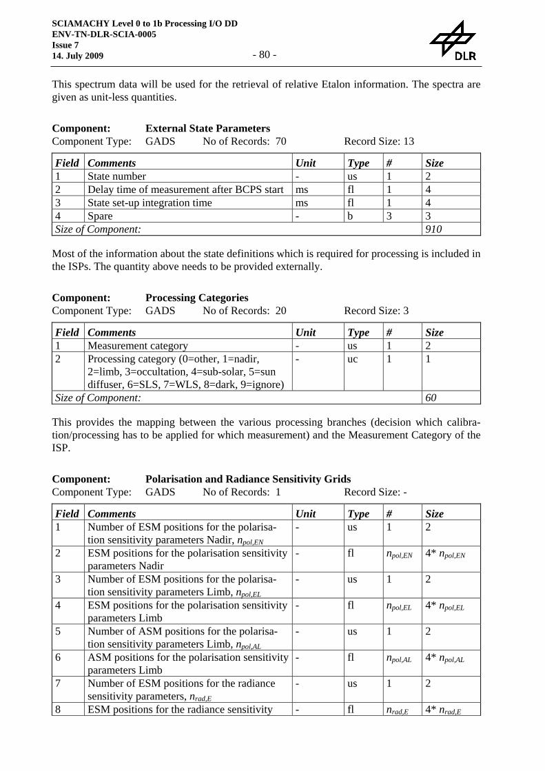
SCIAMACHY Level 0 to 1b Processing I/O DD ENV-TN-DLR-SCIA-0005 Issue 7 14. July 2009 - 80 -
This spectrum data will be used for the retrieval of relative Etalon information. The spectra are given as unit-less quantities.
Component: External State Parameters Component Type: GADS No of Records: 70 Record Size: 13 Field Comments Unit Type # Size 1 State number - us 1 2 2 Delay time of measurement after BCPS start ms fl 1 4 3 State set-up integration time ms fl 1 4 4 Spare - b 3 3 Size of Component: 910
Most of the information about the state definitions which is required for processing is included in the ISPs. The quantity above needs to be provided externally.
Component: Processing Categories Component Type: GADS No of Records: 20 Record Size: 3 Field Comments Unit Type # Size 1 Measurement category - us 1 2 2 Processing category (0=other, 1=nadir,
2=limb, 3=occultation, 4=sub-solar, 5=sun diffuser, 6=SLS, 7=WLS, 8=dark, 9=ignore)
- uc 1 1
Size of Component: 60
This provides the mapping between the various processing branches (decision which calibra-tion/processing has to be applied for which measurement) and the Measurement Category of the ISP.
Component: Polarisation and Radiance Sensitivity Grids Component Type: GADS No of Records: 1 Record Size: - Field Comments Unit Type # Size 1 Number of ESM positions for the polarisa-
tion sensitivity parameters Nadir, npol,EN - us 1 2
2 ESM positions for the polarisation sensitivity parameters Nadir
- fl npol,EN 4* npol,EN
3 Number of ESM positions for the polarisa-tion sensitivity parameters Limb, npol,EL
- us 1 2
4 ESM positions for the polarisation sensitivity parameters Limb
- fl npol,EL 4* npol,EL
5 Number of ASM positions for the polarisa-tion sensitivity parameters Limb, npol,AL
- us 1 2
6 ASM positions for the polarisation sensitivity parameters Limb
- fl npol,AL 4* npol,AL
7 Number of ESM positions for the radiance sensitivity parameters, nrad,E
- us 1 2
8 ESM positions for the radiance sensitivity - fl nrad,E 4* nrad,E
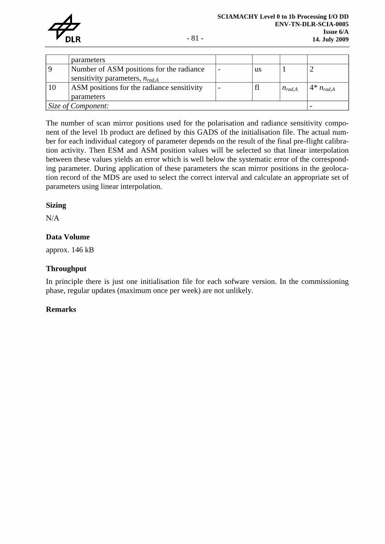
SCIAMACHY Level 0 to 1b Processing I/O DD ENV-TN-DLR-SCIA-0005
Issue 6/A 14. July 2009 - 81 -
parameters 9 Number of ASM positions for the radiance
sensitivity parameters, nrad,A - us 1 2
10 ASM positions for the radiance sensitivity parameters
- fl nrad,A 4* nrad,A
Size of Component: -
The number of scan mirror positions used for the polarisation and radiance sensitivity compo-nent of the level 1b product are defined by this GADS of the initialisation file. The actual num-ber for each individual category of parameter depends on the result of the final pre-flight calibra-tion activity. Then ESM and ASM position values will be selected so that linear interpolation between these values yields an error which is well below the systematic error of the correspond-ing parameter. During application of these parameters the scan mirror positions in the geoloca-tion record of the MDS are used to select the correct interval and calculate an appropriate set of parameters using linear interpolation.
Sizing
N/A
Data Volume
approx. 146 kB
Throughput
In principle there is just one initialisation file for each sofware version. In the commissioning phase, regular updates (maximum once per week) are not unlikely.
Remarks
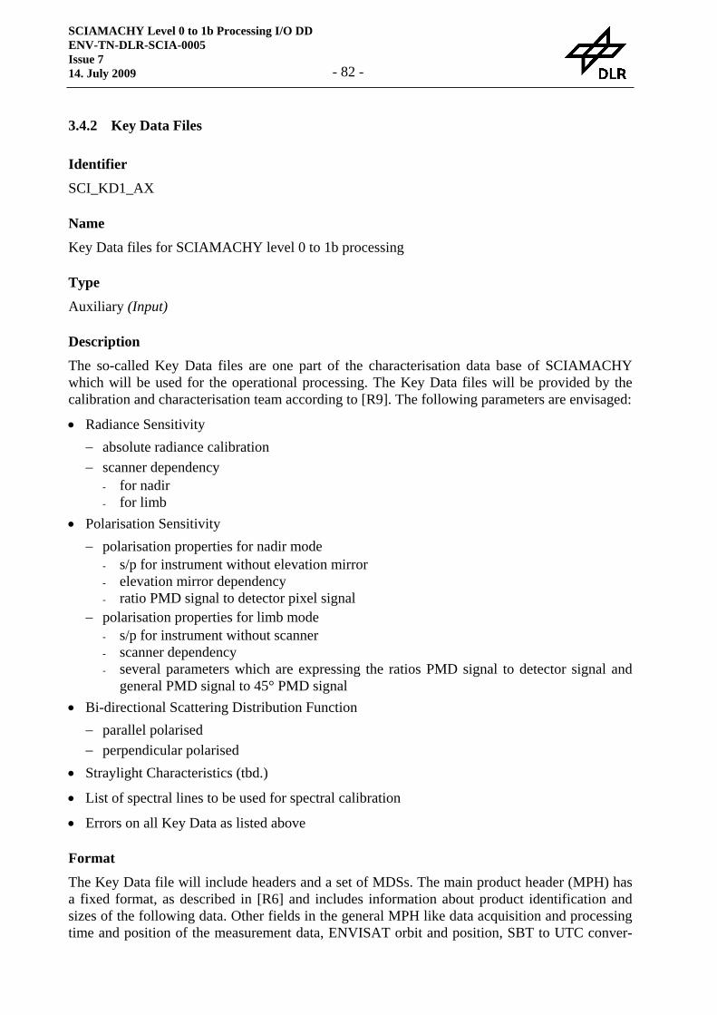
SCIAMACHY Level 0 to 1b Processing I/O DD ENV-TN-DLR-SCIA-0005 Issue 7 14. July 2009 - 82 -
3.4.2 Key Data Files
Identifier
SCI_KD1_AX
Name
Key Data files for SCIAMACHY level 0 to 1b processing
Type
Auxiliary (Input)
Description
The so-called Key Data files are one part of the characterisation data base of SCIAMACHY which will be used for the operational processing. The Key Data files will be provided by the calibration and characterisation team according to [R9]. The following parameters are envisaged:
• Radiance Sensitivity − absolute radiance calibration − scanner dependency
- for nadir - for limb
• Polarisation Sensitivity − polarisation properties for nadir mode
- s/p for instrument without elevation mirror - elevation mirror dependency - ratio PMD signal to detector pixel signal
− polarisation properties for limb mode - s/p for instrument without scanner - scanner dependency - several parameters which are expressing the ratios PMD signal to detector signal and
general PMD signal to 45° PMD signal • Bi-directional Scattering Distribution Function
− parallel polarised − perpendicular polarised
• Straylight Characteristics (tbd.)
• List of spectral lines to be used for spectral calibration
• Errors on all Key Data as listed above
Format
The Key Data file will include headers and a set of MDSs. The main product header (MPH) has a fixed format, as described in [R6] and includes information about product identification and sizes of the following data. Other fields in the general MPH like data acquisition and processing time and position of the measurement data, ENVISAT orbit and position, SBT to UTC conver-
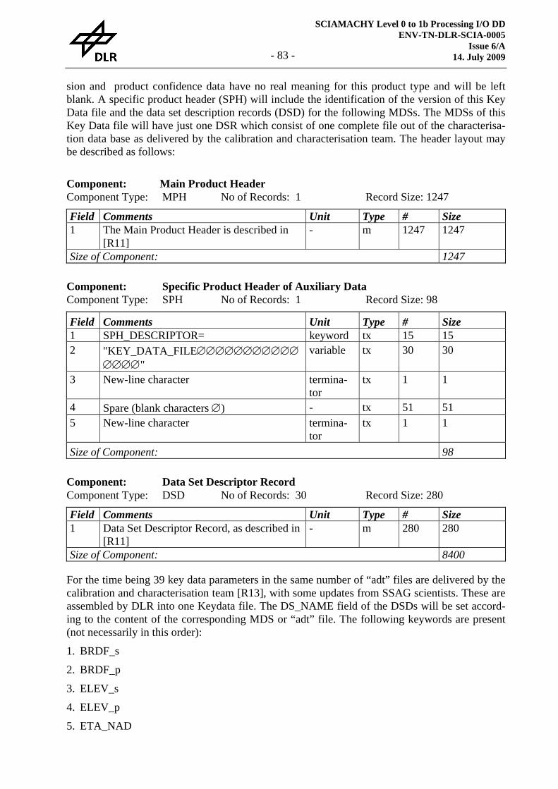
SCIAMACHY Level 0 to 1b Processing I/O DD ENV-TN-DLR-SCIA-0005
Issue 6/A 14. July 2009 - 83 -
sion and product confidence data have no real meaning for this product type and will be left blank. A specific product header (SPH) will include the identification of the version of this Key Data file and the data set description records (DSD) for the following MDSs. The MDSs of this Key Data file will have just one DSR which consist of one complete file out of the characterisa-tion data base as delivered by the calibration and characterisation team. The header layout may be described as follows:
Component: Main Product Header Component Type: MPH No of Records: 1 Record Size: 1247 Field Comments Unit Type # Size 1 The Main Product Header is described in
[R11] - m 1247 1247
Size of Component: 1247
Component: Specific Product Header of Auxiliary Data Component Type: SPH No of Records: 1 Record Size: 98 Field Comments Unit Type # Size 1 SPH_DESCRIPTOR= keyword tx 15 15 2 "KEY_DATA_FILE∅∅∅∅∅∅∅∅∅∅∅
∅∅∅∅" variable tx 30 30
3 New-line character termina-tor
tx 1 1
4 Spare (blank characters ∅) - tx 51 51 5 New-line character termina-
tor tx 1 1
Size of Component: 98
Component: Data Set Descriptor Record Component Type: DSD No of Records: 30 Record Size: 280 Field Comments Unit Type # Size 1 Data Set Descriptor Record, as described in
[R11] - m 280 280
Size of Component: 8400
For the time being 39 key data parameters in the same number of “adt” files are delivered by the calibration and characterisation team [R13], with some updates from SSAG scientists. These are assembled by DLR into one Keydata file. The DS_NAME field of the DSDs will be set accord-ing to the content of the corresponding MDS or “adt” file. The following keywords are present (not necessarily in this order):
1. BRDF_s
2. BRDF_p
3. ELEV_s
4. ELEV_p
5. ETA_NAD
SCIAMACHY Level 0 to 1b Processing I/O DD ENV-TN-DLR-SCIA-0005 Issue 7 14. July 2009 - 84 -
6. XI_NAD
7. OBM_s_p
8. ETA_LIMB
9. ZETA_LIMB
10. EL_AZ_p
11. EL_AZ_s
12. OMEGA_LIMB
13. KAPPA_LIMB
14. XI_LIMB
15. SIGMA_LIMB
16. PSI_LIMB
17. TAU_LIMB
18. SIGMA_NAD
19. PSI_NAD
20. TAU_NAD
21. OMEGA_NAD
22. KAPPA_NAD
23. ZETA_NAD
24. STRAY_UNIFORM
25. STRAY_GHOST
26. STRAY_CH1
27. SPEC_LINE
28. SLIT_F
29. SMALL_AP_SLIT_F
30. ABS_RAD
31. ABS_IRR
32. NDF
33. NDF_s_p
34. MEM_EFFECT_COEF
35. PMD_CROSS_COEF
36. BAD_PIXEL_MASK
37. REF_WLS
38. FRAUNH_LINE
39. NON_LIN
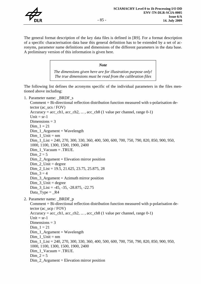
SCIAMACHY Level 0 to 1b Processing I/O DD ENV-TN-DLR-SCIA-0005
Issue 6/A 14. July 2009 - 85 -
The general format description of the key data files is defined in [R9]. For a format description of a specific characterisation data base this general definition has to be extended by a set of ac-ronyms, parameter name definitions and dimensions of the different parameters in the data base. A preliminary version of this information is given here.
Note
The dimensions given here are for illustration purpose only! The true dimensions must be read from the calibration files
The following list defines the acronyms specific of the individual parameters in the files men-tioned above including:
1. Parameter name: _BRDF_s Comment = Bi-directional reflection distribution function measured with s-polarisation de-tector (ac_ucs / FOV) Accuracy = acc_ch1, acc_ch2, ... , acc_ch8 (1 value per channel, range 0-1) Unit = sr-1 Dimensions = 3 Dim_1 = 21 Dim_1_Argument = Wavelength Dim_1_Unit = nm Dim_1_List = 240, 270, 300, 330, 360, 400, 500, 600, 700, 750, 790, 820, 850, 900, 950, 1000, 1100, 1300, 1500, 1900, 2400 Dim_1_Vacuum = .TRUE. Dim_2 = 5 Dim_2_Argument = Elevation mirror position Dim_2_Unit = degree Dim_2_List = 19.5, 21.625, 23.75, 25.875, 28 Dim_3 = 4 Dim_3_Argument = Azimuth mirror position Dim_3_Unit = degree Dim_3_List = -45, -35, -28.875, -22.75 Data_Type = _R4
2. Parameter name: _BRDF_p Comment = Bi-directional reflection distribution function measured with p-polarisation de-tector (ac_ucp / FOV) Accuracy = acc_ch1, acc_ch2, ... , acc_ch8 (1 value per channel, range 0-1) Unit = sr-1 Dimensions = 3 Dim_1 = 21 Dim_1_Argument = Wavelength Dim_1_Unit = nm Dim_1_List = 240, 270, 300, 330, 360, 400, 500, 600, 700, 750, 790, 820, 850, 900, 950, 1000, 1100, 1300, 1500, 1900, 2400 Dim_1_Vacuum = .TRUE. Dim_2 = 5 Dim_2_Argument = Elevation mirror position
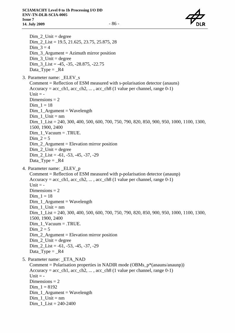
SCIAMACHY Level 0 to 1b Processing I/O DD ENV-TN-DLR-SCIA-0005 Issue 7 14. July 2009 - 86 -
Dim_2_Unit = degree Dim_2_List = 19.5, 21.625, 23.75, 25.875, 28 Dim_3 = 4 Dim_3_Argument = Azimuth mirror position Dim_3_Unit = degree Dim_3_List = -45, -35, -28.875, -22.75 Data_Type = _R4
3. Parameter name: _ELEV_s Comment = Reflection of ESM measured with s-polarisation detector (anauns) Accuracy = acc_ch1, acc_ch2, ... , acc_ch8 (1 value per channel, range 0-1) Unit = - Dimensions = 2 Dim_1 = 18 Dim_1_Argument = Wavelength Dim_1_Unit = nm Dim_1_List = 240, 300, 400, 500, 600, 700, 750, 790, 820, 850, 900, 950, 1000, 1100, 1300, 1500, 1900, 2400 Dim_1_Vacuum = .TRUE. Dim_2 = 5 Dim_2_Argument = Elevation mirror position Dim_2_Unit = degree Dim_2_List = -61, -53, -45, -37, -29 Data_Type = _R4
4. Parameter name: _ELEV_p Comment = Reflection of ESM measured with p-polarisation detector (anaunp) Accuracy = acc_ch1, acc_ch2, ... , acc_ch8 (1 value per channel, range 0-1) Unit = - Dimensions = 2 Dim_1 = 18 Dim_1_Argument = Wavelength Dim_1_Unit = nm Dim_1_List = 240, 300, 400, 500, 600, 700, 750, 790, 820, 850, 900, 950, 1000, 1100, 1300, 1500, 1900, 2400 Dim_1_Vacuum = .TRUE. Dim_2 = 5 Dim_2_Argument = Elevation mirror position Dim_2_Unit = degree Dim_2_List = -61, -53, -45, -37, -29 Data_Type = _R4
5. Parameter name: _ETA_NAD Comment = Polarisation properties in NADIR mode (OBMs_p*(anauns/anaunp)) Accuracy = acc_ch1, acc_ch2, ... , acc_ch8 (1 value per channel, range 0-1) Unit = - Dimensions = 2 Dim_1 = 8192 Dim_1_Argument = Wavelength Dim_1_Unit = nm Dim_1_List = 240-2400
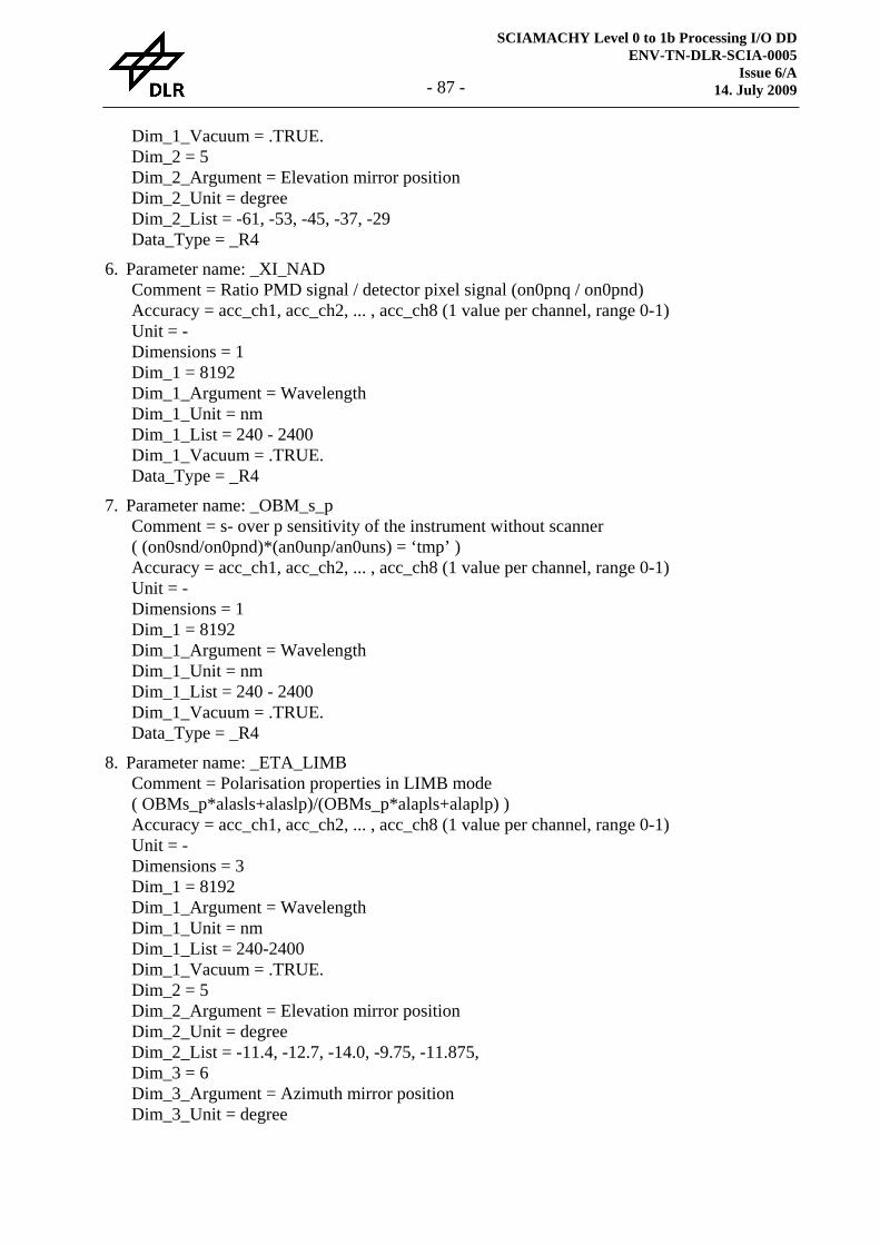
SCIAMACHY Level 0 to 1b Processing I/O DD ENV-TN-DLR-SCIA-0005
Issue 6/A 14. July 2009 - 87 -
Dim_1_Vacuum = .TRUE. Dim_2 = 5 Dim_2_Argument = Elevation mirror position Dim_2_Unit = degree Dim_2_List = -61, -53, -45, -37, -29 Data_Type = _R4
6. Parameter name: _XI_NAD Comment = Ratio PMD signal / detector pixel signal (on0pnq / on0pnd) Accuracy = acc_ch1, acc_ch2, ... , acc_ch8 (1 value per channel, range 0-1) Unit = - Dimensions = 1 Dim_1 = 8192 Dim_1_Argument = Wavelength Dim_1_Unit = nm Dim_1_List = 240 - 2400 Dim_1_Vacuum = .TRUE. Data_Type = _R4
7. Parameter name: _OBM_s_p Comment = s- over p sensitivity of the instrument without scanner ( (on0snd/on0pnd)*(an0unp/an0uns) = ‘tmp’ ) Accuracy = acc_ch1, acc_ch2, ... , acc_ch8 (1 value per channel, range 0-1) Unit = - Dimensions = 1 Dim_1 = 8192 Dim_1_Argument = Wavelength Dim_1_Unit = nm Dim_1_List = 240 - 2400 Dim_1_Vacuum = .TRUE. Data_Type = _R4
8. Parameter name: _ETA_LIMB Comment = Polarisation properties in LIMB mode ( OBMs_p*alasls+alaslp)/(OBMs_p*alapls+alaplp) ) Accuracy = acc_ch1, acc_ch2, ... , acc_ch8 (1 value per channel, range 0-1) Unit = - Dimensions = 3 Dim_1 = 8192 Dim_1_Argument = Wavelength Dim_1_Unit = nm Dim_1_List = 240-2400 Dim_1_Vacuum = .TRUE. Dim_2 = 5 Dim_2_Argument = Elevation mirror position Dim_2_Unit = degree Dim_2_List = -11.4, -12.7, -14.0, -9.75, -11.875, Dim_3 = 6 Dim_3_Argument = Azimuth mirror position Dim_3_Unit = degree
SCIAMACHY Level 0 to 1b Processing I/O DD ENV-TN-DLR-SCIA-0005 Issue 7 14. July 2009 - 88 -
Dim_3_List = -50.4, -39.6, -45.0, -35.0, -22.75, -28.875 Data_Type = _R4
9. Parameter name: _ZETA_LIMB Comment = Polarisation properties –45/45 in LIMB mode Accuracy = acc_ch1, acc_ch2, ... , acc_ch8 (1 value per channel, range 0-1) Unit = - Dimensions = 3 Dim_1 = 8192 Dim_1_Argument = Wavelength Dim_1_Unit = nm Dim_1_List = 240-2400 Dim_1_Vacuum = .TRUE. Dim_2 = 5 Dim_2_Argument = Elevation mirror position Dim_2_Unit = degree Dim_2_List = -11.4, -12.7, -14.0, -9.75, -11.875, Dim_3 = 6 Dim_3_Argument = Azimuth mirror position Dim_3_Unit = degree Dim_3_List = -50.4, -39.6, -45.0, -35.0, -22.75, -28.875 Data_Type = _R4
10. Parameter name: _EL_AZ_p Comment = Elevation and Azimuth scanner calibration with p-polarisation detector (alaulp) Accuracy = acc_ch1, acc_ch2, ... , acc_ch8 (1 value per channel, range 0-1) Unit = - Dimensions = 3 Dim_1 = 18 Dim_1_Argument = Wavelength Dim_1_Unit = nm Dim_1_List = 240, 300, 400, 500, 600, 700, 750, 790, 820, 850, 900, 950, 1000, 1100, 1300, 1500, 1900, 2400 Dim_1_Vacuum = .TRUE. Dim_2 = 5 Dim_2_Argument = Elevation mirror position Dim_2_Unit = degree Dim_2_List = -11.4, -12.7, -14.0, -9.75, -11.875, Dim_3 = 6 Dim_3_Argument = Azimuth mirror position Dim_3_Unit = degree Dim_3_List = -50.4, -39.6, -45.0, -35.0, -22.75, -28.875 Data_Type = _R4
11. Parameter name: _EL_AZ_s Comment = Elevation and Azimuth scanner calibration with s-polarisation detector (alauls) Accuracy = acc_ch1, acc_ch2, ... , acc_ch8 (1 value per channel, range 0-1) Unit = - Dimensions = 3 Dim_1 = 18 Dim_1_Argument = Wavelength
SCIAMACHY Level 0 to 1b Processing I/O DD ENV-TN-DLR-SCIA-0005
Issue 6/A 14. July 2009 - 89 -
Dim_1_Unit = nm Dim_1_List = 240, 300, 400, 500, 600, 700, 750, 790, 820, 850, 900, 950, 1000, 1100, 1300, 1500, 1900, 2400 Dim_1_Vacuum = .TRUE. Dim_2 = 5 Dim_2_Argument = Elevation mirror position Dim_2_Unit = degree Dim_2_List = -11.4, -12.7, -14.0, -9.75, -11.875, Dim_3 = 6 Dim_3_Argument = Azimuth mirror position Dim_3_Unit = degree Dim_3_List = -50.4, -39.6, -45.0, -35.0, -22.75, -28.875 Data_Type = _R4
12. Parameter name: _OMEGA_LIMB Comment = ( (TMP2*ala4lp)/(OBMs_p*ala4ls+ala4lp) ) Accuracy = acc_ch1, acc_ch2, ... , acc_ch8 (1 value per channel, range 0-1) Unit = - Dimensions = 3 Dim_1 = 8192 Dim_1_Argument = Wavelength Dim_1_Unit = nm Dim_1_List = 240-2400 Dim_1_Vacuum = .TRUE. Dim_2 = 5 Dim_2_Argument = Elevation mirror position Dim_2_Unit = degree Dim_2_List = -11.4, -12.7, -14.0, -9.75, -11.875, Dim_3 = 6 Dim_3_Argument = Azimuth mirror position Dim_3_Unit = degree Dim_3_List = -50.4, -39.6, -45.0, -35.0, -22.75, -28.875 Data_Type = _R4
13. Parameter name: _KAPPA_LIMB Comment = ( (TMP2*alaslp)/(OBMs_p*alasls+alaslp) ) Accuracy = acc_ch1, acc_ch2, ... , acc_ch8 (1 value per channel, range 0-1) Unit = - Dimensions = 3 Dim_1 = 8192 Dim_1_Argument = Wavelength Dim_1_Unit = nm Dim_1_List = 240-2400 Dim_1_Vacuum = .TRUE. Dim_2 = 5 Dim_2_Argument = Elevation mirror position Dim_2_Unit = degree Dim_2_List = -11.4, -12.7, -14.0, -9.75, -11.875, Dim_3 = 6 Dim_3_Argument = Azimuth mirror position Dim_3_Unit = degree
SCIAMACHY Level 0 to 1b Processing I/O DD ENV-TN-DLR-SCIA-0005 Issue 7 14. July 2009 - 90 -
Dim_3_List = -50.4, -39.6, -45.0, -35.0, -22.75, -28.875 Data_Type = _R4
14. Parameter name: _XI_LIMB Comment = ( (TMP2*alaplp)/(OBMs_p*alapls+alaplp) ) Accuracy = acc_ch1, acc_ch2, ... , acc_ch8 (1 value per channel, range 0-1) Unit = - Dimensions = 3 Dim_1 = 8192 Dim_1_Argument = Wavelength Dim_1_Unit = nm Dim_1_List = 240-2400 Dim_1_Vacuum = .TRUE. Dim_2 = 5 Dim_2_Argument = Elevation mirror position Dim_2_Unit = degree Dim_2_List = -11.4, -12.7, -14.0, -9.75, -11.875, Dim_3 = 6 Dim_3_Argument = Azimuth mirror position Dim_3_Unit = degree Dim_3_List = -50.4, -39.6, -45.0, -35.0, -22.75, -28.875 Data_Type = _R4
15. Parameter name: _SIGMA_LIMB Comment = ( (TMP3*ala4lx)/(OBMs_p*ala4ls+ala4lp) ) Accuracy = acc_ch1, acc_ch2, ... , acc_ch8 (1 value per channel, range 0-1) Unit = - Dimensions = 3 Dim_1 = 8192 Dim_1_Argument = Wavelength Dim_1_Unit = nm Dim_1_List = 240-2400 Dim_1_Vacuum = .TRUE. Dim_2 = 5 Dim_2_Argument = Elevation mirror position Dim_2_Unit = degree Dim_2_List = -11.4, -12.7, -14.0, -9.75, -11.875, Dim_3 = 6 Dim_3_Argument = Azimuth mirror position Dim_3_Unit = degree Dim_3_List = -50.4, -39.6, -45.0, -35.0, -22.75, -28.875 Data_Type = _R4
16. Parameter name: _PSI_LIMB Comment = ( (TMP3*alaslx)/(OBMs_p*alasls+alaslp) ) Accuracy = acc_ch1, acc_ch2, ... , acc_ch8 (1 value per channel, range 0-1) Unit = - Dimensions = 3 Dim_1 = 8192 Dim_1_Argument = Wavelength Dim_1_Unit = nm
SCIAMACHY Level 0 to 1b Processing I/O DD ENV-TN-DLR-SCIA-0005
Issue 6/A 14. July 2009 - 91 -
Dim_1_List = 240-2400 Dim_1_Vacuum = .TRUE. Dim_2 = 5 Dim_2_Argument = Elevation mirror position Dim_2_Unit = degree Dim_2_List = -11.4, -12.7, -14.0, -9.75, -11.875, Dim_3 = 6 Dim_3_Argument = Azimuth mirror position Dim_3_Unit = degree Dim_3_List = -50.4, -39.6, -45.0, -35.0, -22.75, -28.875 Data_Type = _R4
17. Parameter name: _TAU_LIMB Comment = ( (TMP3*alaplx)/(OBMs_p*alapls+alaplp) ) Accuracy = acc_ch1, acc_ch2, ... , acc_ch8 (1 value per channel, range 0-1) Unit = - Dimensions = 3 Dim_1 = 8192 Dim_1_Argument = Wavelength Dim_1_Unit = nm Dim_1_List = 240-2400 Dim_1_Vacuum = .TRUE. Dim_2 = 5 Dim_2_Argument = Elevation mirror position Dim_2_Unit = degree Dim_2_List = -11.4, -12.7, -14.0, -9.75, -11.875, Dim_3 = 6 Dim_3_Argument = Azimuth mirror position Dim_3_Unit = degree Dim_3_List = -50.4, -39.6, -45.0, -35.0, -22.75, -28.875 Data_Type = _R4
18. Parameter name: _SIGMA_NAD Comment = tbd. Accuracy = acc_ch1, acc_ch2, ... , acc_ch8 (1 value per channel, range 0-1) Unit = - Dimensions = 2 Dim_1 = 8192 Dim_1_Argument = Wavelength Dim_1_Unit = nm Dim_1_List = 240-2400 Dim_1_Vacuum = .TRUE. Dim_2 = 5 Dim_2_Argument = Elevation mirror position Dim_2_Unit = degree Dim_2_List = -61, -53, -45, -37, -29 Data_Type = _R4
19. Parameter name: _PSI_NAD Comment = tbd. Accuracy = acc_ch1, acc_ch2, ... , acc_ch8 (1 value per channel, range 0-1)
SCIAMACHY Level 0 to 1b Processing I/O DD ENV-TN-DLR-SCIA-0005 Issue 7 14. July 2009 - 92 -
Unit = - Dimensions = 1 Dim_1 = 8192 Dim_1_Argument = Wavelength Dim_1_Unit = nm Dim_1_List = 240-2400 Data_Type = _R4
20. Parameter name: _TAU_NAD Comment = tbd. Accuracy = acc_ch1, acc_ch2, ... , acc_ch8 (1 value per channel, range 0-1) Unit = - Dimensions = 1 Dim_1 = 8192 Dim_1_Argument = Wavelength Dim_1_Unit = nm Dim_1_List = 240-2400 Data_Type = _R4
21. Parameter name: _OMEGA_NAD Comment = tbd. Accuracy = acc_ch1, acc_ch2, ... , acc_ch8 (1 value per channel, range 0-1) Unit = - Dimensions = 2 Dim_1 = 8192 Dim_1_Argument = Wavelength Dim_1_Unit = nm Dim_1_List = 240-2400 Dim_1_Vacuum = .TRUE. Dim_2 = 5 Dim_2_Argument = Elevation mirror position Dim_2_Unit = degree Dim_2_List = -61, -53, -45, -37, -29 Data_Type = _R4
22. Parameter name: _KAPPA_NAD Comment = tbd. Accuracy = acc_ch1, acc_ch2, ... , acc_ch8 (1 value per channel, range 0-1) Unit = - Dimensions = 1 Dim_1 = 8192 Dim_1_Argument = Wavelength Dim_1_Unit = nm Dim_1_List = 240-2400 Data_Type = _R4
23. Parameter name: _ZETA_NAD Comment = tbd. Accuracy = acc_ch1, acc_ch2, ... , acc_ch8 (1 value per channel, range 0-1) Unit = - Dimensions = 2 Dim_1 = 8192
SCIAMACHY Level 0 to 1b Processing I/O DD ENV-TN-DLR-SCIA-0005
Issue 6/A 14. July 2009 - 93 -
Dim_1_Argument = Wavelength Dim_1_Unit = nm Dim_1_List = 240-2400 Dim_1_Vacuum = .TRUE. Dim_2 = 5 Dim_2_Argument = Elevation mirror position Dim_2_Unit = degree Dim_2_List = -61, -53, -45, -37, -29 Data_Type = _R4
24. Parameter name: _STRAY_UNIFORM Comment = tbd. Accuracy = acc_ch1, acc_ch2, ... , acc_ch8 (1 value per channel, range 0-1) Unit = - Dimensions = 1 Dim_1 = 8 Dim_1_Argument = Channel nr. Dim_1_Unit = - Data_Type = _R4
25. Parameter name: _STRAY_GHOST Comment = tbd. Accuracy = acc_ch1, acc_ch2, ... , acc_ch8 (1 value per channel, range 0-1) Unit = - Dimensions = 2 Dim_1 = 12 Dim_1_Argument = 3 positions , 2 start pixels, 2 end pixels, 4 intensities, 1 pixel range Dim_1_Unit = - Dim_1_List = P1, P2, P3, min_parent, min_ghost, max_parent, max_ghost, I1, I2, I3, I4 smoothing_width Dim_2 = 17 Dim_2_Argument = Ghost nr. (x.1 = p-polarised, x.2 = s-polarised) Dim_2_List = 1, 3, 4, 5, 6, 7, 8.1, 8.2, 9, 10, 11, 12, 13.1, 13.2, 16, 18, 19 Dim_2_Unit = - Data_Type = _R8*3_I2*4_R8*4_I2
26. Parameter name: _STRAY_CH1 Comment = tbd. Accuracy = acc_ch1, acc_ch2, ... , acc_ch8 (1 value per channel, range 0-1) Unit = - Dimensions = 2 Dim_1 = 1026 (=1024+2) Dim_1_Argument = Target pixel, Source start pixel, Source end pixel (NB start and end pixel refer to filter boundaries) Dim_1_Unit = Dim_1_List = 1 – 1024, startpix (range: 1-5120), endpix (range: 1-5120) Dim_2 = tbd (n_filter *2 for s,p-pol) Dim_2_Argument = Filter nr s/p (sequence: 1p, 1s, 2p, 2s, ...)
SCIAMACHY Level 0 to 1b Processing I/O DD ENV-TN-DLR-SCIA-0005 Issue 7 14. July 2009 - 94 -
Dim_2_Unit = - Dim_2_List = Filter coefficient for each pixel and start/end pixel values Data_Type = _R4*1024_I2*2
27. Parameter name: _SPEC_LINE Comment = Spectral calibration - list of used SLS spectral lines Accuracy = acc_ch1, acc_ch2, ... , acc_ch8 (1 value per channel, range 0-1) Unit = nm Dimensions = 2 Dim_1 ≈ 80 Dim_1_Argument = first guess pixel position Dim_1_Unit = - Dim_1_List = pos1, pos2, ..., posn (range of posi: 1 - 8192) Dim_1_Vacuum = .TRUE. Dim_2 = 2 Dim_2_Argument = Reference wavelength and SLS blocking shift Dim_2_Unit = nm Dim_2_List = External SLS wavelength, (Internal – External) wavelength Data_Type = _R4
28. Parameter name: _SLIT_F Comment = Slit function Dimensions = 2 Dim_1 = 3 Dim_1_Argument = 3 params Dim_1_Unit = - Dim_1_List = type ,FWHM_1,FWHM_2 Dim_2 = 16 Dim_2_Argument = pixel positions Dim_2_Unit = - Dim_2_List = 1 1024 1025 2048 2049 3072 3073 4096 4097 5120 5121 6144 6145 7168 7169 8192 Data_Type = _R4
29. Parameter name: _SMALL_AP_SLIT_F Comment = Slit function with small aperture in beam Dimensions = 2 Dim_1 = 3 Dim_1_Argument = 3 params Dim_1_Unit = - Dim_1_List = type ,FWHM_1,FWHM_2 Dim_2 = 2 Dim_2_Argument = pixel positions Dim_2_Unit = - Dim_2_List = 1 1024 1025 2048 2049 3072 3073 4096 4097 5120 5121 6144 6145 7168 7169 8192 Data_Type = _ R4
30. Parameter name: _ABS_RAD Comment = Absolute radiance calibration Accuracy = acc_ch1, acc_ch2, ... , acc_ch8 (1 value per channel, range 0-1) Unit = (BU/s) / (W/sr.cm3)
SCIAMACHY Level 0 to 1b Processing I/O DD ENV-TN-DLR-SCIA-0005
Issue 6/A 14. July 2009 - 95 -
Dimensions = 1 Dim_1 = 8192 Dim_1_Argument = Wavelength Dim_1_Unit = nm Dim_1_List = 240 - 2400 Dim_1_Vacuum = .TRUE. Data_Type = _R4
31. Parameter name: _ABS_IRR Comment = Absolute irradiance calibration (redundant) Accuracy = acc_ch1, acc_ch2, ... , acc_ch8 (1 value per channel, range 0-1) Unit = (BU/s) / (W/cm3) Dimensions = 1 Dim_1 = 8192 Dim_1_Argument = Wavelength Dim_1_Unit = nm Dim_1_List = 240 - 2400 Dim_1_Vacuum = .TRUE. Data_Type = _R4
32. Parameter name: _NDF Comment = tbd (Transmission function of the neutral density filter) Accuracy = acc_ch1, acc_ch2, ... , acc_ch8 (1 value per channel, range 0-1) Unit = - Dimensions = 1 Dim_1 = 8192 Dim_1_Argument = Wavelength Dim_1_Unit = nm Dim_1_List = 240 - 2400 Dim_1_Vacuum = .TRUE. Data_Type = _R4
33. Parameter name: _NDF_s_p Comment = s- over p sensitivity of the neutral density filter Accuracy = acc_ch1, acc_ch2, ... , acc_ch8 (1 value per channel, range 0-1) Unit = - Dimensions = 1 Dim_1 = 8192 Dim_1_Argument = Wavelength Dim_1_Unit = nm Dim_1_List = 240 - 2400 Dim_1_Vacuum = .TRUE. Data_Type = _R4
34. Parameter name: MEM_EFFECT_COEF Comment = Correction factor for the memory effect of the RETICON detector arrays Accuracy = acc_ch1, acc_ch2, ... , acc_ch8 (1 value per channel, range 0-1) Unit = - Dimensions = 2 Dim_1 = 128 Dim_1_Argument = Raw Signal Values Dim_1_Unit = -
SCIAMACHY Level 0 to 1b Processing I/O DD ENV-TN-DLR-SCIA-0005 Issue 7 14. July 2009 - 96 -
Dim_1_List = 0, 512, 1024, ... , 65024 Dim_2 = 5 Dim_2_Argument = Channel number Dim_2_Unit = - Dim_2_List = 1, 2, 3, 4, 5 Data_Type = _R4
35. Parameter name: PMD_CROSS_COEF Comment = tbd (Parameters for PMD crosstalk) Accuracy = acc_pmd1, acc_pmd2, ... , acc_pmd45, 0 (8 numbers, 1 value per pmd, range 0-1) Unit = - Dimensions = 1 Dim_1 = 6 Dim_1_Argument = Several parameters of the crosstalk effect correction Dim_1_Unit = - Dim_1_List = f1 f2 a1 b0 c0 c1 Data_Type = _I2*3_R8*4
36. Parameter name: BAD_PIXEL_MASK Comment = Accuracy = 0,0,0,0,0,0,0,0 Unit = - Dimensions = 1 Dim_1 = 8192 Dim_1_Argument = Pixel number Dim_1_Unit = - Dim_1_Start = 1 Dim_1_Step = 1 Data_Type = _I2
37. Parameter name: _REF_WLS Comment = tbd (WLS spectrum minus first 8 seconds from ABS_RAD calibration period, corrected for dark signal and (if necessary) straylight) Accuracy = 0,0,0,0,0,0,0,0 (1 value per channel, range 0-1) Unit = - (BU/s) Dimensions = 1 Dim_1 = 8192 Dim_1_Argument = Wavelength Dim_1_Unit = nm Dim_1_List = 240 - 2400 Dim_1_Vacuum = .TRUE. Data_Type = _R4
38. Parameter name: _FRAUNH_LINE Comment = Spectral calibration - list of used Fraunhofer lines Accuracy = acc_ch1, acc_ch2, ... , acc_ch8 (1 value per channel, range 0-1) Unit = nm Dimensions = 2 Dim_1 ≈ 50 Dim_1_Argument = first guess pixel position Dim_1_Unit = -
SCIAMACHY Level 0 to 1b Processing I/O DD ENV-TN-DLR-SCIA-0005
Issue 6/A 14. July 2009 - 97 -
Dim_1_List = pos1, pos2, ..., posn (range of posi: 1 - 8192) Dim_1_Vacuum = .TRUE. Dim_2 = 2 Dim_2_Argument = Reference wavelength and blending shift Dim_2_Unit = nm Dim_2_List = Reference wavelength, blending shift Data_Type = _R4
39. Parameter name: NON_LIN Comment = Created by SRON 7.11.2003 Accuracy = acc_ch1, acc_ch2, ... , acc_ch8 (1 value per channel, range 0-1) Unit = - Dimensions = 2 Dim_1 = 256 Dim_1_Argument = Raw Signal Values Dim_1_Unit = - Dim_1_List = 0, 256, 512, ... , 65280 Dim_2 = 14 Dim_2_Argument = Start pixel number Dim_2_Unit = - Dim_2_List = 5121, 5120, 5633, ... , 7680 Data_Type = _R4
40. (currently not implemented) SMALL_AP_DIFFRAC Comment = tbd (diffraction pattern from small aperture) Accuracy = acc_ch1, acc_ch2, ... , acc_ch8 (1 value per channel, range 0-1) Unit = tbd Dimensions = tbd Data_Type = _R4
Sizing
Each set of parameters of the characterisation data base will be put into a different file by the calibration and characterisation team. These files are put together as the „one and only“ Key Data file using the general MPH/SPH approach defining each of these Key Data files (com-pletely unmodified) to be a GADS of this new Key Data file.
Data Volume
approx. 12 MB
Throughput
In principle there is just one Key Data file for the entire mission; an update to incorporate the actual inflight temperatures may be necessary in the commissioning phase.
Remarks
Parameters 28 and 29 may not be used by level 0 to 1b processing, but they are copied to GADS on the Level 1b product for use in level 1b to 2 processing.
SCIAMACHY Level 0 to 1b Processing I/O DD ENV-TN-DLR-SCIA-0005 Issue 7 14. July 2009 - 98 -
3.4.3 m-Factor File
Identifier
SCI_MF1_AX
Name
SCIAMACHY m-factor file for the level 0 to 1b processing
Type
Auxiliary (Input)
Description
The so-called m-factor files are an extension to the characterisation data base of SCIAMACHY to described the degradation of the instrument during flight. The following parameters are envis-aged by the calibration plan [R10]:
• Ratio of sun diffuser measurements − ratio of the detector array signals
• Ratios of sun occultation measurements − ratio of the detector array signals − ratio of the regular PMD signals − ratio of the 45° PMD signal
• Ratios of sub-solar calibration measurements − ratio of the detector array signals − ratio of the regular PMD signals − ratio of the 45° PMD signal (additional compared to Calibration Plan)
• Ratio of WLS measurements with and without ND filter − ratio of the detector array signals
• Spare ratios of an arbitrary calibration measurements (additional compared to Calibration Plan) − ratio of the detector array signals − ratio of the regular PMD signals − ration of the 45° PMD signal
Format
The m-factor file will include headers and a set of MDSs. The main product header (MPH) has a fixed format, as described in [R6] and includes information about product identification and sizes of the following data. Other fields in the general MPH like data acquisition and processing time and position of the measurement data, ENVISAT orbit and position, SBT to UTC conver-sion and product confidence data have no real meaning for this product type and will be left blank. A specific product header (SPH) will include a SPH descriptor and the data set descrip-tion records (DSD) for the following MDSs. The MDSs of this m-factor file will have just one
SCIAMACHY Level 0 to 1b Processing I/O DD ENV-TN-DLR-SCIA-0005
Issue 6/A 14. July 2009 - 99 -
DSR which consist of one complete file out of the list of different m-factor files as delivered by the SOS team. The header layout may be described as follows:
Component: Main Product Header Component Type: MPH No of Records: 1 Record Size: 1247 Field Comments Unit Type # Size 1 The Main Product Header is described in
[R11] - m 1247 1247
Size of Component: 1247
Component: Specific Product Header of Auxiliary Data Component Type: SPH No of Records: 1 Record Size: 98 Field Comments Unit Type # Size 1 SPH_DESCRIPTOR= keyword tx 15 15 2 "M_FACTOR_FILE∅∅∅∅∅∅∅∅∅∅∅
∅∅∅∅" variable tx 30 30
3 New-line character termina-tor
tx 1 1
4 Spare (blank characters ∅) - tx 51 51 5 New-line character termina-
tor tx 1 1
Size of Component: 98
Component: Data Set Descriptor Record Component Type: DSD No of Records: 11 Record Size: 280 Field Comments Unit Type # Size 1 Data Set Descriptor Record, as described in
[R11] - m 280 280
Size of Component: 3080
For the time being 10 m-factor parameters in the same number of m-factor files are expected by the SOS team [R10]. The DS_NAME field of the DSDs will be set according to the content of the corresponding MDS or m-factor file. The following keywords are envisaged:
• from sun diffuser measurements 1. M_CAL
• from sun occultation 2. M_DL 3. M_PL 4. M_QL
• from sub-solar calibration 5. M_DN 6. M_PN 7. M_QN
SCIAMACHY Level 0 to 1b Processing I/O DD ENV-TN-DLR-SCIA-0005 Issue 7 14. July 2009 - 100 -
• from WLS measurements 8. M_NDF
• spare m-factor set (e.g. from moon occultation) 9. M_DS 10. M_PS 11. M_QS
The general format description of these files is defined in [R9]. For a format description of a specific characterisation data base this general definition has to be extended by a set of acro-nyms, parameter name definitions and dimensions of the different correction factors. A first ver-sion of this information will be given here, because the characterisation activity was even not yet started and it is very likely that also this information (like the characterisation data base) is sub-ject to change.
The following list defines the acronyms specific of the individual m-factors in the files men-tioned above:
• Sun viewing via diffuser with ND filter ratio 1. Parameter name: _M_FACTOR_CAL
Comment = Ratio of the array detector signals between a reference sun diffuser measure-ment with the neutral density filter inserted and a corresponding measurement at a certain time Accuracy = tbd. Unit = <none> Dimensions = 1 Dim_1 = 8192 Dim_1_Argument = Wavelength Dim_1_Unit = nm Dim_1_List = 240-2400 Data_Type = _R4
• Sun occultation measurement ratio 2. Parameter name: _M_FACTOR_DL
Comment = Ratio of the array detector signals between a reference sun occultation meas-urement and a corresponding measurement at a certain time Accuracy = tbd. Unit = <none> Dimensions = 1 Dim_1 = 8192 Dim_1_Argument = Wavelength Dim_1_Unit = nm Dim_1_List = 240-2400 Data_Type = _R4
3. Parameter name: _M_FACTOR_PL Comment = Ratio of the regular PMD signals between a reference sun occultation meas-urement and a corresponding measurement at a certain time Accuracy = tbd. Unit = <none> Dimensions = 1 Dim_1 = 6
SCIAMACHY Level 0 to 1b Processing I/O DD ENV-TN-DLR-SCIA-0005
Issue 6/A 14. July 2009 - 101 -
Dim_1_Argument = PMD number Dim_1_Unit = <none> Dim_1_Start = 1 Dim_1_Step = 1 Data_Type = _R4
4. Parameter name: _M_FACTOR_QL Comment = Ratio of the 45° PMD signal between a reference sun occultation measure-ment and a corresponding measurement at a certain time Accuracy = tbd. Unit = <none> Dimensions = 1 Dim_1 = 1 Dim_1_Unit = <none> Data_Type = _R4
• Sub-solar calibration measurement ratio 5. Parameter name: _M_FACTOR_DN
Comment = Ratio of the array detector signals between a reference sub-solar calibration measurement and a corresponding measurement at a certain time Accuracy = tbd. Unit = <none> Dimensions = 1 Dim_1 = 8192 Dim_1_Argument = Wavelength Dim_1_Unit = nm Dim_1_List = 240-2400 Data_Type = _R4
6. Parameter name: _M_FACTOR_PN Comment = Ratio of the regular PMD signals between a reference sub-solar calibration measurement and a corresponding measurement at a certain time Accuracy = tbd. Unit = <none> Dimensions = 1 Dim_1 = 6 Dim_1_Argument = PMD number Dim_1_Unit = <none> Dim_1_Start = 1 Dim_1_Step = 1 Data_Type = _R4
7. Parameter name: _M_FACTOR_QN Comment = Ratio of the 45° PMD signal between a reference sub-solar calibration meas-urement and a corresponding measurement at a certain time Accuracy = tbd. Unit = <none> Dimensions = 1 Dim_1 = 1 Dim_1_Unit = <none> Data_Type = _R4
• WLS with / without ND filter ratio
SCIAMACHY Level 0 to 1b Processing I/O DD ENV-TN-DLR-SCIA-0005 Issue 7 14. July 2009 - 102 -
8. Parameter name: _M_FACTOR_NDF Comment = (tbd) Accuracy = tbd. Unit = <none> Dimensions = 1 Dim_1 = 8192 Dim_1_Argument = Wavelength Dim_1_Unit = nm Dim_1_List = 240-2400 Data_Type = _R4
• Spare ratio 9. Parameter name: _M_FACTOR_DS
Comment = Ratio of the array detector signals between a reference spare calibration measurement and a corresponding measurement at a certain time Accuracy = tbd. Unit = <none> Dimensions = 1 Dim_1 = 8192 Dim_1_Argument = Wavelength Dim_1_Unit = nm Dim_1_List = 240-2400 Data_Type = _R4
10. Parameter name: _M_FACTOR_PS Comment = Ratio of the regular PMD signals between a reference spare calibration meas-urement and a corresponding measurement at a certain time Accuracy = tbd. Unit = <none> Dimensions = 1 Dim_1 = 6 Dim_1_Argument = PMD number Dim_1_Unit = <none> Dim_1_Start = 1 Dim_1_Step = 1 Data_Type = _R4
11. Parameter name: _M_FACTOR_QS Comment = Ratio of the 45° PMD signal between a reference spare calibration measure-ment and a corresponding measurement at a certain time Accuracy = tbd. Unit = <none> Dimensions = 1 Dim_1 = 1 Dim_1_Unit = <none> Data_Type = _R4
Sizing
All m-factors will be put into one file.

SCIAMACHY Level 0 to 1b Processing I/O DD ENV-TN-DLR-SCIA-0005
Issue 6/A 14. July 2009 - 103 -
Data Volume
approx. 1.0 MB
Throughput
Major calibration measurements are planned every month during normal operation of SCIA-MACHY. Therefore, it is expected that a new set of m-factors may be generated once per month.
Remarks
SCIAMACHY Level 0 to 1b Processing I/O DD ENV-TN-DLR-SCIA-0005 Issue 7 14. July 2009 - 104 -
4 Generic Data Representations
The data representations used throughout this data definition document follow a number of con-ventions which are stated as guidelines in [R6]. No other data types were used. The basic data types are listed in section 4.1 and are defined in more detail in section 3.1 on page 22. All data types which are indicated by ‘m’ (mixed data type) are composed of a combination of these ge-neric data types and are described in the documents mentioned in the ‘Comments’ section of the format tables. Mixed or compound data types which are specific to the present document are defined in section 4.2.
4.1 Basic Data Types
Basic data types are the following:
• signed or unsigned character (1 byte)
• signed or unsigned short integer (2 byte)
• signed or unsigned long integer (4 byte)
• signed or unsigned long integer (8 byte)
• single precision floating-point number (4 byte)
• double precision floating-point number (8 byte)
• bit fields (any number of bytes up to 8)
• time formats − UTC − MJD 2000
• geographical location
• orbit state vectors
Details may be found in the above mentioned document.
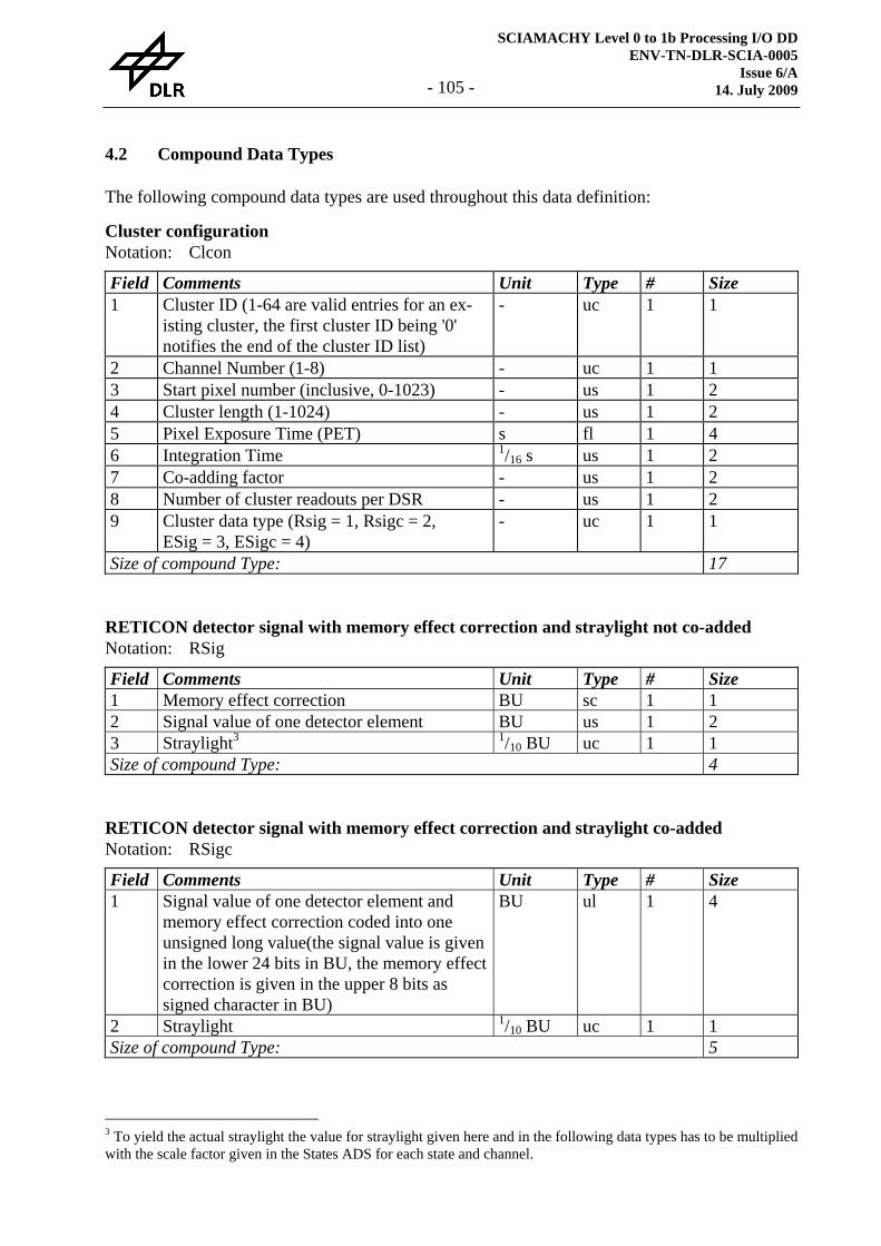
SCIAMACHY Level 0 to 1b Processing I/O DD ENV-TN-DLR-SCIA-0005
Issue 6/A 14. July 2009 - 105 -
4.2 Compound Data Types
The following compound data types are used throughout this data definition:
Cluster configuration Notation: Clcon
Field Comments Unit Type # Size 1 Cluster ID (1-64 are valid entries for an ex-
isting cluster, the first cluster ID being '0' notifies the end of the cluster ID list)
- uc 1 1
2 Channel Number (1-8) - uc 1 1 3 Start pixel number (inclusive, 0-1023) - us 1 2 4 Cluster length (1-1024) - us 1 2 5 Pixel Exposure Time (PET) s fl 1 4 6 Integration Time 1/16 s us 1 2 7 Co-adding factor - us 1 2 8 Number of cluster readouts per DSR - us 1 2 9 Cluster data type (Rsig = 1, Rsigc = 2,
ESig = 3, ESigc = 4) - uc 1 1
Size of compound Type: 17
RETICON detector signal with memory effect correction and straylight not co-added Notation: RSig Field Comments Unit Type # Size 1 Memory effect correction BU sc 1 1 2 Signal value of one detector element BU us 1 2 3 Straylight3 1/10 BU uc 1 1 Size of compound Type: 4
RETICON detector signal with memory effect correction and straylight co-added Notation: RSigc Field Comments Unit Type # Size 1 Signal value of one detector element and
memory effect correction coded into one unsigned long value(the signal value is given in the lower 24 bits in BU, the memory effect correction is given in the upper 8 bits as signed character in BU)
BU ul 1 4
2 Straylight 1/10 BU uc 1 1 Size of compound Type: 5
3 To yield the actual straylight the value for straylight given here and in the following data types has to be multiplied with the scale factor given in the States ADS for each state and channel.
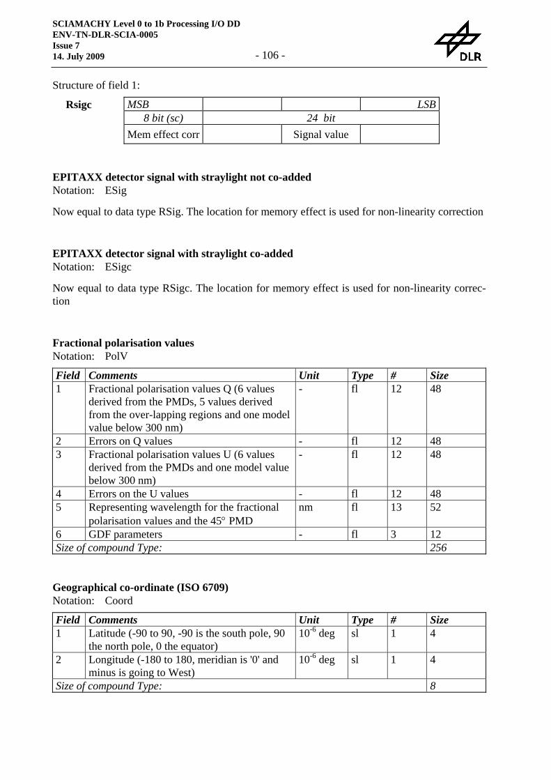
SCIAMACHY Level 0 to 1b Processing I/O DD ENV-TN-DLR-SCIA-0005 Issue 7 14. July 2009 - 106 -
Structure of field 1:
MSB LSB 8 bit (sc) 24 bit
Rsigc
Mem effect corr Signal value
EPITAXX detector signal with straylight not co-added Notation: ESig Now equal to data type RSig. The location for memory effect is used for non-linearity correction
EPITAXX detector signal with straylight co-added Notation: ESigc Now equal to data type RSigc. The location for memory effect is used for non-linearity correc-tion
Fractional polarisation values Notation: PolV Field Comments Unit Type # Size 1 Fractional polarisation values Q (6 values
derived from the PMDs, 5 values derived from the over-lapping regions and one model value below 300 nm)
- fl 12 48
2 Errors on Q values - fl 12 48 3 Fractional polarisation values U (6 values
derived from the PMDs and one model value below 300 nm)
- fl 12 48
4 Errors on the U values - fl 12 48 5 Representing wavelength for the fractional
polarisation values and the 45° PMD nm fl 13 52
6 GDF parameters - fl 3 12 Size of compound Type: 256
Geographical co-ordinate (ISO 6709) Notation: Coord Field Comments Unit Type # Size 1 Latitude (-90 to 90, -90 is the south pole, 90
the north pole, 0 the equator) 10-6 deg sl 1 4
2 Longitude (-180 to 180, meridian is '0' and minus is going to West)
10-6 deg sl 1 4
Size of compound Type: 8
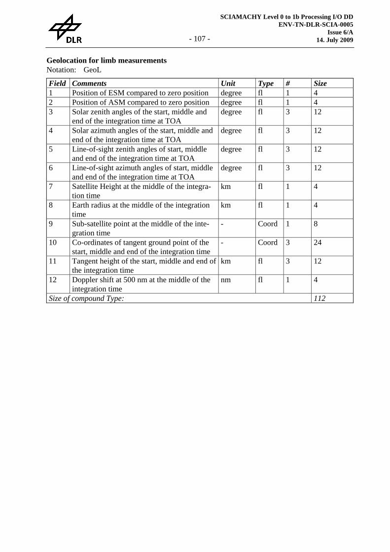
SCIAMACHY Level 0 to 1b Processing I/O DD ENV-TN-DLR-SCIA-0005
Issue 6/A 14. July 2009 - 107 -
Geolocation for limb measurements Notation: GeoL Field Comments Unit Type # Size 1 Position of ESM compared to zero position degree fl 1 4 2 Position of ASM compared to zero position degree fl 1 4 3 Solar zenith angles of the start, middle and
end of the integration time at TOA degree fl 3 12
4 Solar azimuth angles of the start, middle and end of the integration time at TOA
degree fl 3 12
5 Line-of-sight zenith angles of start, middle and end of the integration time at TOA
degree fl 3 12
6 Line-of-sight azimuth angles of start, middle and end of the integration time at TOA
degree fl 3 12
7 Satellite Height at the middle of the integra-tion time
km fl 1 4
8 Earth radius at the middle of the integration time
km fl 1 4
9 Sub-satellite point at the middle of the inte-gration time
- Coord 1 8
10 Co-ordinates of tangent ground point of the start, middle and end of the integration time
- Coord 3 24
11 Tangent height of the start, middle and end of the integration time
km fl 3 12
12 Doppler shift at 500 nm at the middle of the integration time
nm fl 1 4
Size of compound Type: 112
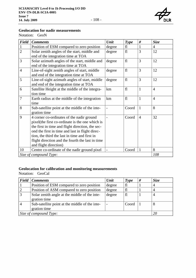
SCIAMACHY Level 0 to 1b Processing I/O DD ENV-TN-DLR-SCIA-0005 Issue 7 14. July 2009 - 108 -
Geolocation for nadir measurements Notation: GeoN Field Comments Unit Type # Size 1 Position of ESM compared to zero position degree fl 1 4 2 Solar zenith angles of the start, middle and
end of the integration time at TOA degree fl 3 12
3 Solar azimuth angles of the start, middle and end of the integration time at TOA
degree fl 3 12
4 Line-of-sight zenith angles of start, middle and end of the integration time at TOA
degree fl 3 12
5 Line-of-sight azimuth angles of start, middle and end of the integration time at TOA
degree fl 3 12
6 Satellite Height at the middle of the integra-tion time
km fl 1 4
7 Earth radius at the middle of the integration time
km fl 1 4
8 Sub-satellite point at the middle of the inte-gration time
- Coord 1 8
9 4 corner co-ordinates of the nadir ground pixel(the first co-ordinate is the one which is the first in time and flight direction, the sec-ond the first in time and last in flight direc-tion, the third the last in time and first in flight direction and the fourth the last in time and flight direction)
- Coord 4 32
10 Centre co-ordinate of the nadir ground pixel - Coord 1 8 Size of compound Type: 108
Geolocation for calibration and monitoring measurements Notation: GeoCal Field Comments Unit Type # Size 1 Position of ESM compared to zero position degree fl 1 4 2 Position of ASM compared to zero position degree fl 1 4 3 Solar zenith angle at the middle of the inte-
gration time degree fl 1 4
4 Sub-satellite point at the middle of the inte-gration time
- Coord 1 8
Size of compound Type: 20
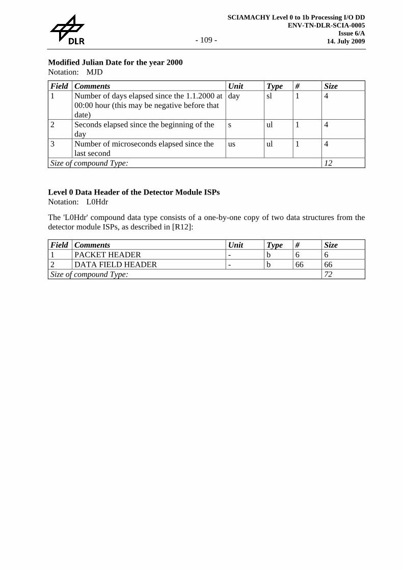
SCIAMACHY Level 0 to 1b Processing I/O DD ENV-TN-DLR-SCIA-0005
Issue 6/A 14. July 2009 - 109 -
Modified Julian Date for the year 2000 Notation: MJD Field Comments Unit Type # Size 1 Number of days elapsed since the 1.1.2000 at
00:00 hour (this may be negative before that date)
day sl 1 4
2 Seconds elapsed since the beginning of the day
s ul 1 4
3 Number of microseconds elapsed since the last second
us ul 1 4
Size of compound Type: 12
Level 0 Data Header of the Detector Module ISPs Notation: L0Hdr The 'L0Hdr' compound data type consists of a one-by-one copy of two data structures from the detector module ISPs, as described in [R12]:
Field Comments Unit Type # Size 1 PACKET HEADER - b 6 6 2 DATA FIELD HEADER - b 66 66 Size of compound Type: 72
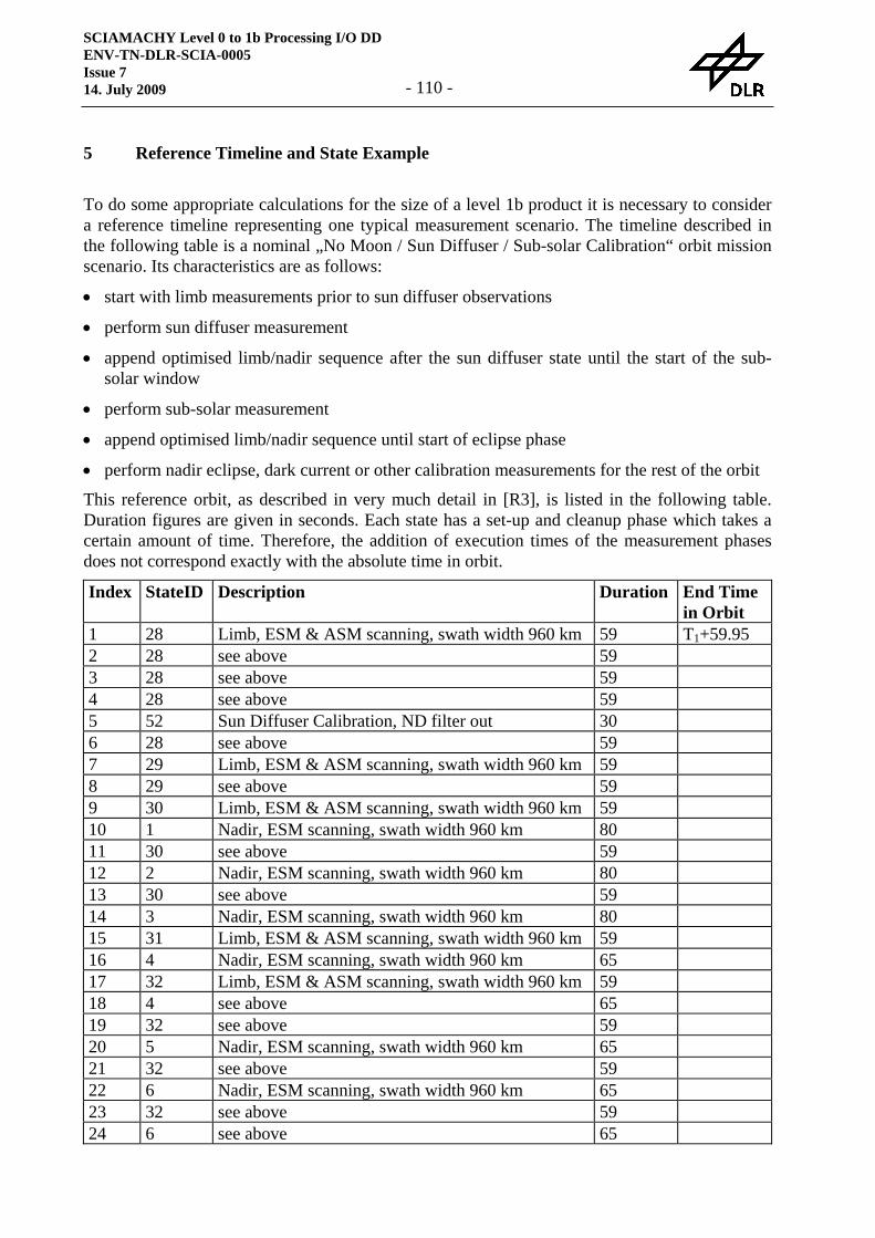
SCIAMACHY Level 0 to 1b Processing I/O DD ENV-TN-DLR-SCIA-0005 Issue 7 14. July 2009 - 110 -
5 Reference Timeline and State Example
To do some appropriate calculations for the size of a level 1b product it is necessary to consider a reference timeline representing one typical measurement scenario. The timeline described in the following table is a nominal „No Moon / Sun Diffuser / Sub-solar Calibration“ orbit mission scenario. Its characteristics are as follows:
• start with limb measurements prior to sun diffuser observations
• perform sun diffuser measurement
• append optimised limb/nadir sequence after the sun diffuser state until the start of the sub-solar window
• perform sub-solar measurement
• append optimised limb/nadir sequence until start of eclipse phase
• perform nadir eclipse, dark current or other calibration measurements for the rest of the orbit
This reference orbit, as described in very much detail in [R3], is listed in the following table. Duration figures are given in seconds. Each state has a set-up and cleanup phase which takes a certain amount of time. Therefore, the addition of execution times of the measurement phases does not correspond exactly with the absolute time in orbit.
Index StateID Description Duration End Time in Orbit
1 28 Limb, ESM & ASM scanning, swath width 960 km 59 T1+59.95 2 28 see above 59 3 28 see above 59 4 28 see above 59 5 52 Sun Diffuser Calibration, ND filter out 30 6 28 see above 59 7 29 Limb, ESM & ASM scanning, swath width 960 km 59 8 29 see above 59 9 30 Limb, ESM & ASM scanning, swath width 960 km 59 10 1 Nadir, ESM scanning, swath width 960 km 80 11 30 see above 59 12 2 Nadir, ESM scanning, swath width 960 km 80 13 30 see above 59 14 3 Nadir, ESM scanning, swath width 960 km 80 15 31 Limb, ESM & ASM scanning, swath width 960 km 59 16 4 Nadir, ESM scanning, swath width 960 km 65 17 32 Limb, ESM & ASM scanning, swath width 960 km 59 18 4 see above 65 19 32 see above 59 20 5 Nadir, ESM scanning, swath width 960 km 65 21 32 see above 59 22 6 Nadir, ESM scanning, swath width 960 km 65 23 32 see above 59 24 6 see above 65
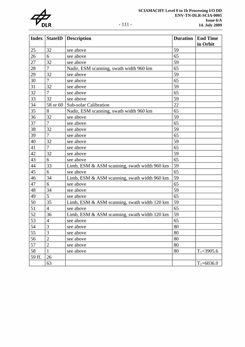
SCIAMACHY Level 0 to 1b Processing I/O DD ENV-TN-DLR-SCIA-0005
Issue 6/A 14. July 2009 - 111 -
Index StateID Description Duration End Time in Orbit
25 32 see above 59 26 6 see above 65 27 32 see above 59 28 7 Nadir, ESM scanning, swath width 960 km 65 29 32 see above 59 30 7 see above 65 31 32 see above 59 32 7 see above 65 33 32 see above 59 34 58 or 60 Sub-solar Calibration 22 35 8 Nadir, ESM scanning, swath width 960 km 65 36 32 see above 59 37 7 see above 65 38 32 see above 59 39 7 see above 65 40 32 see above 59 41 7 see above 65 42 32 see above 59 43 6 see above 65 44 33 Limb, ESM & ASM scanning, swath width 960 km 59 45 6 see above 65 46 34 Limb, ESM & ASM scanning, swath width 960 km 59 47 6 see above 65 48 34 see above 59 49 5 see above 65 50 35 Limb, ESM & ASM scanning, swath width 120 km 59 51 4 see above 65 52 36 Limb, ESM & ASM scanning, swath width 120 km 59 53 4 see above 65 54 3 see above 80 55 3 see above 80 56 2 see above 80 57 2 see above 80 58 1 see above 80 T1+3905.6 59 ff. 26 63 T1+6036.0
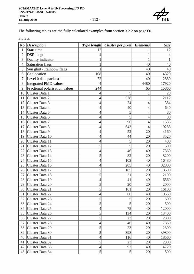
SCIAMACHY Level 0 to 1b Processing I/O DD ENV-TN-DLR-SCIA-0005 Issue 7 14. July 2009 - 112 -
The following tables are the fully calculated examples from section 3.2.2 on page 60.
State 3:
No Description Type length Cluster per pixel Elements Size1 Start time 12 1 1 122 DSR length 4 1 43 Quality indicator 1 1 1 14 Saturation flags 1 1 40 405 Sun glint / Rainbow flags 1 40 406 Geolocation 108 1 40 43207 Level 0 data packest 72 1 40 28808 Integrated PMD values 4 1 4480 179209 Fractional polarisation values 244 1 65 1586010 Cluster Data 1 4 5 1 2011 Cluster Data 2 4 528 1 211212 Cluster Data 3 4 24 4 38413 Cluster Data 4 4 40 4 64014 Cluster Data 5 4 5 4 8015 Cluster Data 6 4 5 4 8016 Cluster Data 7 4 96 4 153617 Cluster Data 8 4 643 4 1028818 Cluster Data 9 4 52 20 416019 Cluster Data 10 4 44 20 352020 Cluster Data 11 4 5 20 40021 Cluster Data 12 5 5 20 50022 Cluster Data 13 4 46 40 736023 Cluster Data 14 5 82 20 820024 Cluster Data 15 4 103 40 1648025 Cluster Data 16 4 205 40 3280026 Cluster Data 17 5 185 20 1850027 Cluster Data 18 5 21 20 210028 Cluster Data 19 4 41 40 656029 Cluster Data 20 5 20 20 200030 Cluster Data 21 5 161 20 1610031 Cluster Data 22 4 66 40 1056032 Cluster Data 23 5 5 20 50033 Cluster Data 24 5 5 20 50034 Cluster Data 25 4 75 40 1200035 Cluster Data 26 5 134 20 1340036 Cluster Data 27 5 23 20 230037 Cluster Data 28 4 46 40 736038 Cluster Data 29 5 23 20 230039 Cluster Data 30 5 398 20 3980040 Cluster Data 31 4 116 40 1856041 Cluster Data 32 5 23 20 230042 Cluster Data 33 4 92 40 1472043 Cluster Data 34 5 5 20 500
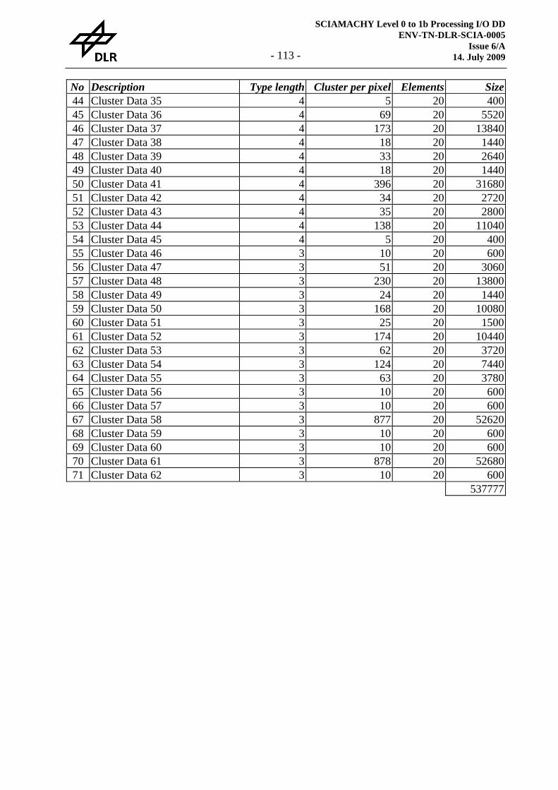
SCIAMACHY Level 0 to 1b Processing I/O DD ENV-TN-DLR-SCIA-0005
Issue 6/A 14. July 2009 - 113 -
No Description Type length Cluster per pixel Elements Size44 Cluster Data 35 4 5 20 40045 Cluster Data 36 4 69 20 552046 Cluster Data 37 4 173 20 1384047 Cluster Data 38 4 18 20 144048 Cluster Data 39 4 33 20 264049 Cluster Data 40 4 18 20 144050 Cluster Data 41 4 396 20 3168051 Cluster Data 42 4 34 20 272052 Cluster Data 43 4 35 20 280053 Cluster Data 44 4 138 20 1104054 Cluster Data 45 4 5 20 40055 Cluster Data 46 3 10 20 60056 Cluster Data 47 3 51 20 306057 Cluster Data 48 3 230 20 1380058 Cluster Data 49 3 24 20 144059 Cluster Data 50 3 168 20 1008060 Cluster Data 51 3 25 20 150061 Cluster Data 52 3 174 20 1044062 Cluster Data 53 3 62 20 372063 Cluster Data 54 3 124 20 744064 Cluster Data 55 3 63 20 378065 Cluster Data 56 3 10 20 60066 Cluster Data 57 3 10 20 60067 Cluster Data 58 3 877 20 5262068 Cluster Data 59 3 10 20 60069 Cluster Data 60 3 10 20 60070 Cluster Data 61 3 878 20 5268071 Cluster Data 62 3 10 20 600 537777
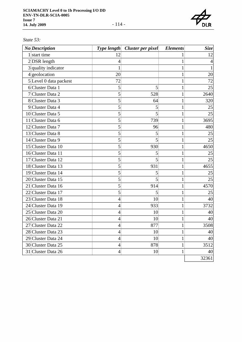
SCIAMACHY Level 0 to 1b Processing I/O DD ENV-TN-DLR-SCIA-0005 Issue 7 14. July 2009 - 114 -
State 53:
No Description Type length Cluster per pixel Elements Size1 start time 12 1 1 122 DSR length 4 1 1 43 quality indicator 1 1 1 14 geolocation 20 1 1 205 Level 0 data packest 72 1 1 726 Cluster Data 1 5 5 1 257 Cluster Data 2 5 528 1 26408 Cluster Data 3 5 64 1 3209 Cluster Data 4 5 5 1 25
10 Cluster Data 5 5 5 1 2511 Cluster Data 6 5 739 1 369512 Cluster Data 7 5 96 1 48013 Cluster Data 8 5 5 1 2514 Cluster Data 9 5 5 1 2515 Cluster Data 10 5 930 1 465016 Cluster Data 11 5 5 1 2517 Cluster Data 12 5 5 1 2518 Cluster Data 13 5 931 1 465519 Cluster Data 14 5 5 1 2520 Cluster Data 15 5 5 1 2521 Cluster Data 16 5 914 1 457022 Cluster Data 17 5 5 1 2523 Cluster Data 18 4 10 1 4024 Cluster Data 19 4 933 1 373225 Cluster Data 20 4 10 1 4026 Cluster Data 21 4 10 1 4027 Cluster Data 22 4 877 1 350828 Cluster Data 23 4 10 1 4029 Cluster Data 24 4 10 1 4030 Cluster Data 25 4 878 1 351231 Cluster Data 26 4 10 1 40
32361