this document (en 50588-1:2017) has ... - iteh standards store
TRANSCRIPT
2003-01.Slovenski inštitut za standardizacijo. Razmnoževanje celote ali delov tega standarda ni dovoljeno.
Močnostni transformatorji srednje moči 50 Hz z najvišjo napetostjo naprave do 36kV - 1. del: Splošne zahteve
Mittelleistungstransformatoren 50 Hz, mit einer höchsten Spannung für Betriebsmittel nicht über 36 kV - Teil 1: Allgemeine Anforderungen
Transformateurs 50 Hz de moyenne puissance, de tension la plus élevée pour le matériel ne dépassant pas 36 kV - Partie 1: Exigences générales
Medium power transformers 50 Hz, with highest voltage for equipment not exceeding 36 kV - Part 1: General requirements
29.180 Transformatorji. Dušilke Transformers. Reactors
ICS:
Ta slovenski standard je istoveten z: EN 50588-1:2017
SIST EN 50588-1:2017 en
01-november-2017
SIST EN 50588-1:2017SLOVENSKI STANDARD
SIST EN 50588-1:2015/A1:2016SIST EN 50588-1:2015
Nadomešča:
iTeh STANDARD PREVIEW(standards.iteh.ai)
SIST EN 50588-1:2017https://standards.iteh.ai/catalog/standards/sist/c5dea890-7c1f-414b-96c6-
a05123854656/sist-en-50588-1-2017
SIST EN 50588-1:2017
iTeh STANDARD PREVIEW(standards.iteh.ai)
SIST EN 50588-1:2017https://standards.iteh.ai/catalog/standards/sist/c5dea890-7c1f-414b-96c6-
a05123854656/sist-en-50588-1-2017
EUROPEAN STANDARD
NORME EUROPÉENNE
EUROPÄISCHE NORM
EN 50588-1
September 2017
ICS 29.180 Supersedes EN 50588-1:2015
English Version
Medium power transformers 50 Hz, with highest voltage for equipment not exceeding 36 kV - Part 1: General requirements
Transformateurs 50 Hz de moyenne puissance, de tension la plus élevée pour le matériel ne dépassant pas 36 kV -
Partie 1: Exigences générales
Mittelleistungstransformatoren 50 Hz, mit einer höchsten Spannung für Betriebsmittel nicht über 36 kV - Teil 1:
Allgemeine Anforderungen
This European Standard was approved by CENELEC on 2017-07-03. CENELEC members are bound to comply with the CEN/CENELEC Internal Regulations which stipulate the conditions for giving this European Standard the status of a national standard without any alteration.
Up-to-date lists and bibliographical references concerning such national standards may be obtained on application to the CEN-CENELEC Management Centre or to any CENELEC member.
This European Standard exists in three official versions (English, French, German). A version in any other language made by translation under the responsibility of a CENELEC member into its own language and notified to the CEN-CENELEC Management Centre has the same status as the official versions.
CENELEC members are the national electrotechnical committees of Austria, Belgium, Bulgaria, Croatia, Cyprus, the Czech Republic, Denmark, Estonia, Finland, Former Yugoslav Republic of Macedonia, France, Germany, Greece, Hungary, Iceland, Ireland, Italy, Latvia, Lithuania, Luxembourg, Malta, the Netherlands, Norway, Poland, Portugal, Romania, Serbia, Slovakia, Slovenia, Spain, Sweden, Switzerland, Turkey and the United Kingdom.
European Committee for Electrotechnical Standardization Comité Européen de Normalisation Electrotechnique
Europäisches Komitee für Elektrotechnische Normung
CEN-CENELEC Management Centre: Avenue Marnix 17, B-1000 Brussels
© 2017 CENELEC All rights of exploitation in any form and by any means reserved worldwide for CENELEC Members.
Ref. No. EN 50588-1:2017 E
SIST EN 50588-1:2017
iTeh STANDARD PREVIEW(standards.iteh.ai)
SIST EN 50588-1:2017https://standards.iteh.ai/catalog/standards/sist/c5dea890-7c1f-414b-96c6-
a05123854656/sist-en-50588-1-2017
EN 50588-1:2017 (E)
2
Contents Page
European foreword ....................................................................................................... 3 1 Scope ...................................................................................................................... 4 2 Normative references ............................................................................................. 5 3 Terms and definitions ............................................................................................ 6 4 Environmental classes ........................................................................................... 8 5 Electrical characteristics ....................................................................................... 8
5.1 Highest voltages for equipment for winding with Um > 1,1 kV .................... 8 5.2 Rated voltage for winding with Um ≤ 1,1 kV ................................................ 8 5.3 Tapping .......................................................................................................... 9 5.4 Connection designations for three phase transformers ............................. 9
6 Load loss, no load loss, PEI, sound power level, short-circuit impedance ......... 9 6.1 General .......................................................................................................... 9 6.2 Transformers with rated power Sr ≤ 3 150 kVA .......................................... 10 6.3 Transformers with rated power 3 150 kVA < Sr < 40 000 kVA.................... 14 6.4 Transformers with special requirements ................................................... 15
7 Tolerances ............................................................................................................ 17 7.1 Tolerances during factory acceptance tests .............................................. 17 7.2 Tolerances for Market surveillance ............................................................ 18 7.3 Uncertainties for market surveillance verification .................................... 19
8 Rating plate .......................................................................................................... 19 9 Tests ..................................................................................................................... 20
9.1 Routine tests ............................................................................................... 20 9.2 Type tests .................................................................................................... 20 9.3 Special tests ................................................................................................ 20 9.4 Special test for corrugated tank ................................................................. 20 9.5 Other technologies with level of no load loss AAA0 .................................. 22
10 Design requirements ............................................................................................ 22 10.1 Liquid immersed transformers ................................................................... 22 10.2 Dry-type transformers ................................................................................. 23
11 Accessories .......................................................................................................... 23 11.1 Liquid immersed transformers ................................................................... 23 11.2 Dry-type transformers ................................................................................. 24
Annex A (informative) Calculation of PEI and kPEI ..................................................... 25 Annex B (informative) A-deviations ........................................................................... 27 Annex ZZ (informative) Relationship between this European Standard and the
ecodesign requirements of Commission Regulation (EU) No 548/2014 aimed to be covered ............................................................................................................ 28
Bibliography ............................................................................................................... 31
SIST EN 50588-1:2017
iTeh STANDARD PREVIEW(standards.iteh.ai)
SIST EN 50588-1:2017https://standards.iteh.ai/catalog/standards/sist/c5dea890-7c1f-414b-96c6-
a05123854656/sist-en-50588-1-2017
EN 50588-1:2017 (E)
3
European foreword
This document (EN 50588-1:2017) has been prepared by CLC/TC 14 "Power transformers".
The following dates are fixed:
• latest date by which this document has to be implemented at national level by publication of an identical national standard or by endorsement
(dop) [2018-07-03]
• latest date by which the national standards conflicting with this document have to be withdrawn
(dow) [2020-07-03]
This document supersedes EN 50588-1:2015 and EN 50588-1:2015/A1:2016.
EN 50588-1:2017 includes the following significant technical changes with respect to EN 50588-1:2015 and EN 50588-1:2015/A1:2016:
- definition of declared values.
This document has been prepared under a mandate given to CENELEC by the European Commission and the European Free Trade Association, and supports essential requirements of EU Directive(s).
For the relationship with EU Directive(s) see informative Annex ZZ, which is an integral part of this document.
SIST EN 50588-1:2017
iTeh STANDARD PREVIEW(standards.iteh.ai)
SIST EN 50588-1:2017https://standards.iteh.ai/catalog/standards/sist/c5dea890-7c1f-414b-96c6-
a05123854656/sist-en-50588-1-2017
EN 50588-1:2017 (E)
4
1 Scope
This European Standard covers medium power transformers. ‘Medium power transformer’ means a power transformer with a highest voltage for equipment higher than 1,1 kV, but not exceeding 36 kV and a rated power equal to or higher than 5 kVA but lower than 40 MVA.
National practices may require the use of highest voltages for equipment up to (but not including) 52 kV, when the rated voltage is less than 36 kV (such as Um = 38,5 kV or Um = 40,5 kV). This is considered to be an unusual case of a large power transformer, where the requirements are those for a medium power transformer with Um = 36 kV.
NOTE 1 ‘Large power transformer’ means a power transformer with a highest voltage for equipment exceeding 36 kV and a rated power equal to or higher than 5 kVA, or a rated power equal to or higher than 40 MVA regardless of the highest voltage for equipment. Large power transformers are in the scope of EN 50629.
NOTE 2 Transformers with tap changer (DETC or OLTC) are included in this European Standard even if they have separate tapping winding.
The object of this European Standard is to set up requirements related to electrical characteristics and design of medium power transformers.
The following transformers are excluded from this European Standard:
a) instrument transformers, specifically designed to supply measuring instruments, meters, relays and other similar apparatus;
b) transformers with low-voltage windings specifically designed for use with rectifiers to provide a DC supply;
c) transformers specifically designed to be directly connected to a furnace;
d) transformers specifically designed for offshore applications and floating offshore applications;
e) transformers specially designed for emergency installations;
f) transformers and auto-transformers specifically designed for railway feeding systems;
g) earthing or grounding transformers, this is, three-phase transformers intended to provide a neutral point for system grounding purposes;
h) traction transformers mounted on rolling stock, this is, transformers connected to an AC or DC contact line, directly or through a converter, used in fixed installations of railway applications;
i) starting transformers, specifically designed for starting three-phase induction motors so as to eliminate supply voltage dips;
j) testing transformers, specifically designed to be used in a circuit to produce a specific voltage or current for the purpose of testing electrical equipment;
k) welding transformers, specifically designed for use in arc welding equipment or resistance welding equipment;
l) transformers specifically designed for explosion-proof and underground mining applications;
m) transformers specifically designed for deep water (submerged) applications;
n) medium Voltage (MV) to Medium Voltage (MV) interface transformers up to 5 MVA;
o) large power transformers where it is demonstrated that for a particular application, technically feasible alternatives are not available to meet the minimum efficiency requirements set out by the commission regulation (EU) No 548/2014;
p) large power transformers which are like for like replacements in the same physical location/installation for existing large power transformers, where this replacement cannot be
SIST EN 50588-1:2017
iTeh STANDARD PREVIEW(standards.iteh.ai)
SIST EN 50588-1:2017https://standards.iteh.ai/catalog/standards/sist/c5dea890-7c1f-414b-96c6-
a05123854656/sist-en-50588-1-2017
EN 50588-1:2017 (E)
5
achieved without entailing disproportionate costs associated to their transportation and/or installation.
In case one of the last two exclusions is claimed, this should be documented at the signature of the contract with a declaration made by the customer.
NOTE 3 This standard covers the transformers under the Commission Regulation (EU) No. 548/2014 and gives additional specific guidance for single phase transformers, multi winding transformers and for transformers with OF or OD cooling systems, necessary for the correct application of energy efficiency requirements to these categories of transformers.
2 Normative references
The following documents are referred to in the text in such a way that some or all of their content constitutes requirements of this document. For dated references, only the edition cited applies. For undated references, the latest edition of the referenced document (including any amendments) applies.
EN 50180, Bushings above 1 kV up to 52 kV and from 250 A to 3,15 kA for liquid filled transformers – Part 1: General requirements for bushings
EN 50181, Plug-in type bushings above 1 kV up to 52 kV and from 250 A to 2,50 kA for equipment other than liquid filled transformers
EN 50216 (all parts), Power transformer and reactor fittings
EN 50329, Railway applications - Fixed installations - Traction transformers
EN 50386, Bushings up to 1 kV and from 250 A to 5 kA, for liquid filled transformers
EN 50387, Busbar bushings up to 1 kV and from 1,25 kA to 5 kA, for liquid filled transformers
EN 50464-4, Three-phase oil-immersed distribution transformers 50 Hz, from 50 kVA to 2 500 kVA with highest voltage for equipment not exceeding 36 kV - Part 4: Requirements and tests concerning pressurised corrugated tanks
EN 60076-1:2011, Power transformers - Part 1: General (IEC 60076-1:2011)
EN 60076-6:2008, Power transformers - Part 6: Reactors (IEC 60076-6:2007)
EN 60076 (all parts), Power transformers (IEC 60076, all parts)
EN 60085, Electrical insulation - Thermal evaluation and designation (IEC 60085)
EN 60505, Evaluation and qualification of electrical insulation systems (IEC 60505)
EN 61100, Classification of insulating liquids according to fire point and net calorific value (IEC 61100)
EN 61378-1, Convertor transformers - Part 1: Transformers for industrial applications (IEC 61378-1)
EN 61869-1:2009, Instrument transformers - Part 1: General requirements
IEC/TR 60616, Terminal and tapping markings for power transformers
SIST EN 50588-1:2017
iTeh STANDARD PREVIEW(standards.iteh.ai)
SIST EN 50588-1:2017https://standards.iteh.ai/catalog/standards/sist/c5dea890-7c1f-414b-96c6-
a05123854656/sist-en-50588-1-2017
EN 50588-1:2017 (E)
6
3 Terms and definitions
For the purposes of this document, the terms and definitions given in EN 60076-1:2011 and the following apply.
3.1 load factor k ratio of actual input current over the rated current of transformer where the actual current and rated current are constant over time
Note 1 to entry: Normally 0 ≤ k ≤ 1.
3.2 transmitted apparent power kSr product of the load factor and the rated power
3.3 Efficiency Index EI ratio of the transmitted apparent power of a transformer minus electrical losses to the transmitted apparent power of the transformer
3.4 Peak Efficiency Index PEI highest value of efficiency index that can be achieved at the optimum value of load factor
Note 1 to entry: See Annex A for derivation.
3.5 load factor of Peak Efficiency Index kPEI load factor at which Peak Efficiency Index occurs
Note 1 to entry: See Annex A for derivation.
3.6 declared value of loss loss measured by the manufacturer and written in the test report and on the rating plate
Note 1 to entry: This definition applies both to no load loss and to load loss.
Note 2 to entry: Declared values and guaranteed values according to EN 60076-1 are two different concepts. Guaranteed values are related to contract, whereas declared values are related to compliance verifications with COMMISSION REGULATION (EU) No 548/2014.
3.7 declared value of electrical power required by the cooling system for no load operation electrical power required by fan and liquid pump motors for no load operation as derived from the test certificates
Note 1 to entry: The electrical power required by the cooling system for no load operation is not measured all the times, because this is a type test according to EN 60076-1.
SIST EN 50588-1:2017
iTeh STANDARD PREVIEW(standards.iteh.ai)
SIST EN 50588-1:2017https://standards.iteh.ai/catalog/standards/sist/c5dea890-7c1f-414b-96c6-
a05123854656/sist-en-50588-1-2017
EN 50588-1:2017 (E)
7
3.8 declared value of PEI PEI calculated from the declared values of no load loss, load loss and power required by the cooling system for no load operation according to the definitions 3.6 and 3.7 and to the formula in A.1
3.10 excluded transformers
3.10.1 instrument transformer transformer as defined in subclause 3.1.1 of EN 61869-1:2009, even if it supplies energy for the operation of connected equipment
Note 1 to entry: The difference between the definition in Regulation 548/2014 and the CENELEC one is in the use of the word ‘supply’ rather than ‘transmit an information signal’.
3.10.2 transformer with low-voltage windings specifically designed for use with rectifiers to provide a DC supply transformer specifically designed and intended to supply power electronic or rectifier loads specified according to EN 61378-1
Note 1 to entry: This definition covers transformers designed for use with rectifiers to provide a DC supply in certain applications.
Note 2 to entry: The term “low-voltage winding” refers to the winding having the lowest rated voltage as per EN 60076-1, whatever its voltage level.
Note 3 to entry: This definition does not include:
— transformers which are intended to provide AC from DC sources such as transformers for wind turbine and photo voltaic applications;
— transformers designed for DC transmission and distribution applications.
Therefore, they are part of the scope of this standard and should comply with Commission Regulation (EU) No. 548/2014.
3.10.3 transformers specifically designed for offshore applications and floating offshore applications transformer to be installed on fixed or floating offshore platforms, offshore wind turbines or on board of ships and all kind of vessels
3.10.4 transformers specially designed for emergency installations transformer designed only to provide cover for a specific time limited situation when the normal power supply is interrupted either due to an unplanned occurrence such as failure or a station refurbishment, but not to permanently upgrade an existing substation
Note 1 to entry: Such transformer could have some specific features that make it suitable for emergency or temporary use as opposed to normal use. Examples of some specific features include:
— multiple windings making it suitable for use at several locations;
— special low weight or dimensions for easy transport, or special capability to be disassembled into smaller units for transport;
— increased overload capability achieved by the use of special materials;
— permanent mounting on a transporter arrangement.
SIST EN 50588-1:2017
iTeh STANDARD PREVIEW(standards.iteh.ai)
SIST EN 50588-1:2017https://standards.iteh.ai/catalog/standards/sist/c5dea890-7c1f-414b-96c6-
a05123854656/sist-en-50588-1-2017
EN 50588-1:2017 (E)
8
3.10.5 transformers and auto-transformers specifically designed for railway feeding systems transformer as defined in EN 50329
3.10.6 earthing or grounding transformers, this is, three-phase transformers intended to provide a neutral point for system grounding purposes transformer as defined in subclause 3.1.10 of EN 60076-6:2008
3.10.7 traction transformer transformer installed on board of rolling stock inserted in the traction and auxiliary circuits of rolling stock and in the scope of EN 60310
3.10.8 starting transformers, specifically designed for starting three-phase induction motors so as to eliminate supply voltage dips transformer that is de energized during normal operation, used for the purpose of starting a rotating machine
3.10.9 Medium Voltage (MV) to Medium Voltage (MV) interface transformers up to 5 MVA transformer used in network voltage conversion program and placed at the junction between two voltage levels of two MV networks and which needs to be able to cope with emergency overloads
Note 1 to entry: Such units may or maybe not part of a packaged compact substation including also MV Reclosers and protection equipment.
4 Environmental classes
Classification of insulating liquids according to fire point and net calorific value is given in EN 61100. Climatic, environmental and fire behaviour classes for dry-type transformers are defined in EN 60076-11.
5 Electrical characteristics
5.1 Highest voltages for equipment for winding with Um > 1,1 kV
Insulation levels and dielectric test shall be in accordance with the requirements of EN 60076-3 and for dry type transformers in accordance with EN 60076-11.
The values of the highest voltage Um for equipment are:
3,6 kV– 7,2 kV – 12 kV – 17,5 kV – 24 kV – 36 kV
NOTE National practices may require the use of highest voltages for equipment up to (but not including) 52 kV, when the rated voltage is less than 36 kV (such as Um = 38,5 kV or Um = 40,5 kV).
5.2 Rated voltage for winding with Um ≤ 1,1 kV
For Um ≤ 1,1 kV, the preferred rated voltage value shall be chosen in the hereunder list:
400 V – 410 V – 415 V – 420 V – 433 V – 690 V
This document may be applied either as a whole or in part, to transformers with rated low voltages below 400 V and above 690 V.
The values for short duration power frequency withstand and/or for the lightning impulse withstand test between windings and earth need to be stated by the purchaser. Typical values are respectively 10 kV and 30 kV.
SIST EN 50588-1:2017
iTeh STANDARD PREVIEW(standards.iteh.ai)
SIST EN 50588-1:2017https://standards.iteh.ai/catalog/standards/sist/c5dea890-7c1f-414b-96c6-
a05123854656/sist-en-50588-1-2017
EN 50588-1:2017 (E)
9
5.3 Tapping
Taps can be provided with DETC or OLTC devices:
— DETC: De-energized tap changer;
— OLTC: On load tap changer.
For DETC, the preferred tapping ranges are ± 2,5 % with 3 tap positions and ± 2 x 2,5 % with 5 tap positions. On special request ± 4 x 2,5 % with 9 tap positions can be provided. Tapping ranges greater than ± 10 % or with more than 9 tap positions are unusual and subject to specific agreement.
For transformer equipped with OLTC, the tapping range shall be smaller than ± 15 % with a maximum of 17 tap positions. Tapping ranges greater than ± 15 % or with more than 17 tap positions are unusual and subject to specific agreement.
Tapping ranges outside the above definitions have to be specified by agreement between manufacturer and purchaser.
5.4 Connection designations for three phase transformers
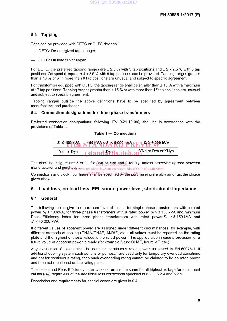
Preferred connection designations, following IEV [421-10-09], shall be in accordance with the provisions of Table 1.
Table 1 — Connections
Sr ≤ 100 kVA 100 kVA < Sr < 5 000 kVA Sr ≥ 5 000 kVA
Yzn or Dyn Dyn YNd or Dyn or YNyn
The clock hour figure are 5 or 11 for Dyn or Yzn and 0 for Yy, unless otherwise agreed between manufacturer and purchaser.
Connections and clock hour figure shall be specified by the purchaser preferably amongst the choice given above.
6 Load loss, no load loss, PEI, sound power level, short-circuit impedance
6.1 General
The following tables give the maximum level of losses for single phase transformers with a rated power Sr ≤ 100kVA, for three phase transformers with a rated power Sr ≤ 3 150 kVA and minimum Peak Efficiency Index for three phase transformers with rated power Sr > 3 150 kVA and Sr < 40 000 kVA.
If different values of apparent power are assigned under different circumstances, for example, with different methods of cooling (ONAN/ONAF, AN/AF, etc.), all values must be reported on the rating plate and the highest of these values is the rated power. This applies also in case a provision for a future value of apparent power is made (for example future ONAF, future AF, etc.).
Any evaluation of losses shall be done on continuous rated power as stated in EN 60076-1. If additional cooling system such as fans or pumps… are used only for temporary overload conditions and not for continuous rating, then such overloading rating cannot be claimed to be as rated power and then not mentioned on the rating plate.
The losses and Peak Efficiency Index classes remain the same for all highest voltage for equipment values (Um) regardless of the additional loss corrections specified in 6.2.3, 6.2.4 and 6.2.5.
Description and requirements for special cases are given in 6.4.
SIST EN 50588-1:2017
iTeh STANDARD PREVIEW(standards.iteh.ai)
SIST EN 50588-1:2017https://standards.iteh.ai/catalog/standards/sist/c5dea890-7c1f-414b-96c6-
a05123854656/sist-en-50588-1-2017
EN 50588-1:2017 (E)
10
Several classes of losses are defined in this standard with a ranking of efficiency for no load loss and for load loss. The most efficient class for no load loss is class AAA0, then AA0, then A0. For load loss, the same logic is used with the most efficient class is Ak, then Bk, then Ck.
The loss classes correspond to the values measured during the factory acceptance test without any tolerances.
The names of the loss classes are the same for all of the highest voltage for equipment values (Um) whatever the corrections done on the values described in the following clauses.
Other values of short-circuit impedance can be specified by the purchaser for particular system service conditions, e.g. in the case of parallel operations in all tables of this clause.
The sound power levels, given in the tables in Clause 6 are maximum values when specified. The sound power levels can be specified by the purchaser or by agreement between manufacturer and purchaser for different values.
For liquid immersed transformer and for dry-type transformer, load loss, Peak Efficiency Index and short circuit impedance shall be given at the reference temperature defined in EN 60076-1.
More specifically:
a) The reference temperature for liquid immersed transformers with rated average winding temperature rise less than or equal to 65 K for OF or ON, or 70 K for OD is 75 °C;
b) For transformers with other rated average winding temperature rise, the reference temperature is equal to the rated average winding temperature rise + 20 °C, or rated winding temperature rise + yearly external cooling medium average temperature, whichever is higher.
If a purchaser needs to compare transformer with different insulation systems and different average winding temperature rises, the reference temperature should be according to b) above.
To calculate and to compare the Peak Efficiency Index and the load loss of different transformers the correct reference temperature shall be taken according to their insulation system temperature (see EN 60076-1:2011, 11.1.1).
The insulation materials used in transformer shall have an insulation system temperature according to EN 60085 and EN 60505 and in compliance with the temperature rise limits for the transformer according to EN 60076-2, EN 60076-11 and EN 60076-14.
The symbols used are:
P0: no load loss at rated voltage and rated frequency, on the rated tap according to EN 60076-1;
Pk: load loss at rated current and rated frequency on the rated tap corrected to reference temperature according to EN 60076-1;
LWA: A weighted sound power level of transformers according to EN 60076-10.
NOTE Loss levels and correction factors defined in 6.2 and 6.4 refer to two winding medium power transformers. Loss levels for three winding medium power transformers are not defined due to lack of data at the time of the publication of this standard. PEI definition for three winding transformers with rated power 3 150 kVA < Sr < 40 000 kVA is given in 6.3.
6.2 Transformers with rated power Sr ≤ 3 150 kVA
6.2.1 General information
Figure 1 indicates clauses to be chosen according to the highest voltage for equipment values Um on the primary and on the secondary windings.
SIST EN 50588-1:2017
iTeh STANDARD PREVIEW(standards.iteh.ai)
SIST EN 50588-1:2017https://standards.iteh.ai/catalog/standards/sist/c5dea890-7c1f-414b-96c6-
a05123854656/sist-en-50588-1-2017