8200510 2017-12-12 wa121545 bama en
TRANSCRIPT

E Schaudt GmbH, Elektrotechnik und Apparatebau, Planckstraße 8, 88677 Markdorf, Germany, Tel. +49 7544 9577-0, Fax +49 7544 9577-29, www.schaudt.gmbh
8200510 BA / EN Date: 12.12.2017
Operating Instructions
Booster WA 121545
Table of contents
1 Safety information 2. . . . . . . . . . . . . . . . . . . . . . . . . . . . . . . . . . . . . .1.1 Meaning of safety symbols 2. . . . . . . . . . . . . . . . . . . . . . . . . . . . . . .1.2 General safety instructions 2. . . . . . . . . . . . . . . . . . . . . . . . . . . . . . .1.3 Liability limitation 3. . . . . . . . . . . . . . . . . . . . . . . . . . . . . . . . . . . . . . .2 Introduction 3. . . . . . . . . . . . . . . . . . . . . . . . . . . . . . . . . . . . . . . . . . . .3 Application and functions in detail 4. . . . . . . . . . . . . . . . . . . . . . . . .4 Operation 5. . . . . . . . . . . . . . . . . . . . . . . . . . . . . . . . . . . . . . . . . . . . . .5 Technical details 5. . . . . . . . . . . . . . . . . . . . . . . . . . . . . . . . . . . . . . . .5.1 Electrical details 5. . . . . . . . . . . . . . . . . . . . . . . . . . . . . . . . . . . . . . . .5.2 Mechanical details 6. . . . . . . . . . . . . . . . . . . . . . . . . . . . . . . . . . . . . .6 Installation 7. . . . . . . . . . . . . . . . . . . . . . . . . . . . . . . . . . . . . . . . . . . . .7 Electrical connection 8. . . . . . . . . . . . . . . . . . . . . . . . . . . . . . . . . . . .7.1 Connection sets 9. . . . . . . . . . . . . . . . . . . . . . . . . . . . . . . . . . . . . . . .7.2 Booster connector for standard EBLs -- grounds of both
batteries on the booster 12. . . . . . . . . . . . . . . . . . . . . . . . . . . . . . . . . .7.3 Booster connector for EBLs with SDTBUS and appropriate
panel -- grounds of both batteries on the booster 13. . . . . . . . . . . .7.4 Booster connector for directly on batteries 14. . . . . . . . . . . . . . . . . .7.5 Booster connector for directly on batteries with
additional chargers 15. . . . . . . . . . . . . . . . . . . . . . . . . . . . . . . . . . . . . .7.6 Connecting the temperature and battery sensor (optional) 15. . . .7.7 Finishing installation work 16. . . . . . . . . . . . . . . . . . . . . . . . . . . . . . . .8 Adjustments 17. . . . . . . . . . . . . . . . . . . . . . . . . . . . . . . . . . . . . . . . . . .8.1 Control and display panel 17. . . . . . . . . . . . . . . . . . . . . . . . . . . . . . . .8.2 Meaning of the display 18. . . . . . . . . . . . . . . . . . . . . . . . . . . . . . . . . . .8.3 Displaying current settings 18. . . . . . . . . . . . . . . . . . . . . . . . . . . . . . .8.4 Adjusting the booster 19. . . . . . . . . . . . . . . . . . . . . . . . . . . . . . . . . . . .9 Initial use 23. . . . . . . . . . . . . . . . . . . . . . . . . . . . . . . . . . . . . . . . . . . . . .10 Faults 23. . . . . . . . . . . . . . . . . . . . . . . . . . . . . . . . . . . . . . . . . . . . . . . . .11 Maintenance 24. . . . . . . . . . . . . . . . . . . . . . . . . . . . . . . . . . . . . . . . . . .
Appendix 25. . . . . . . . . . . . . . . . . . . . . . . . . . . . . . . . . . . . . . . . . . . . . .

Operating Instructions Booster WA 121545
2 Date: 12.12.2017 8200510 BA / EN
1 Safety information
1.1 Meaning of safety symbols
Y DANGER!Failure to comply with this sign may result in danger to life or physical con-dition.
Y WARNING!Failure to comply with this sign may result in injury.
Y ATTENTION!Failure to comply with the sign may result in damage to equipment or otherconnected consumers.
1.2 General safety instructions
The design of the device is state-of-the-art and complies with approved sa-fety regulations. Failure to observe the safety instructions may nonethelesslead to injury or damage to the device.
Only use the device when it is in perfect technical condition.
Any faults affecting the safety of individuals or the proper functioning of thedevice must be repaired immediately by specialists.
Y DANGER!230V units carrying mains voltage.Risk of fatal injury due to electric shock or fire:
F Do not carry out maintenance or repair work on the device
F If cables or the device housing are damaged, no longer use the deviceand isolate it from the power supply
F Ensure that no liquids enter the device
F The mains connection line may only be replaced by an authorised cu-stomer service department or by those qualified.
Y WARNING!Hot componentsBurns:
F Only change blown fuses when the device is fully de-energised
F Blown fuses may only be replaced once the cause of the fault isknown and has been rectified
F Never bypass or repair fuses
F Only use original fuses rated as specified on the device
F Device parts can become hot during operation. Do not touch them.
F Never store heat sensitive objects close to the device (e.g. tempera-ture sensitive clothes if the device has been installed in a wardrobe)
Operating Instructions Booster WA 121545
3Date: 12.12.20178200510 BA / EN
1.3 Liability limitation
All technical information, details and instructions for installation, operationand maintenance were up-to-date at the time of print, and are provided ingood faith and in due consideration of our experience and knowledge gainedto date.
No claims can be derived from the specifications, figures and descriptions inthese instructions. The manufacturer assumes no liability for damage due to:
F failure to comply with these instructions
F non-intended use
F improper repairs
F technical modifications
F use of non-approved spare parts
Translations are carried out in good faith. We assume no liability for transla-tion mistakes, neither when translations are performed by ourselves nor onour behalf. Only the original German text remains binding.
2 Introduction
This instruction manual contains important information for the safe operationof equipment supplied by Schaudt. Make sure you read and follow the safetyinstructions provided.
The operating instructions should always be kept in the vehicle. All safetyinformation must be passed on to other users.
Y This device is not intended to be used by those (including children) withlimited physical, sensory or mental aptitude or lack of experience and/orknowledge unless they are supervised by a person responsible for theirsafety or have received instruction from this person as to how the deviceis used.
Children must be supervised to ensure they do not play with the device.
This device is intended for installation into a vehicle.
Operating Instructions Booster WA 121545
4 Date: 12.12.2017 8200510 BA / EN
3 Application and functions in detail
The WA 121545 booster is used for optimal charging of leisure areabatteries in vehicles whilst they are moving (e.g. in motorhomes) with 12Vsystems.
The following battery types can be set:
F Lead-acid
F Lead-gel
F AGM
F Lithium
Y A working 12V battery with a minimum capacity of 80 Ah must be con-nected for operation.
Generators with energy-saving charge strategies are often fitted in EURO 6vehicles. The charge voltage for these generators varies greatly dependingon the driving state (between 12.6 V and 15.0 V on the MB Sprinter forexample).
Without a booster, this prevent optimum charging of the leisure area battery.There is even a risk of discharge for a battery fully charged from the 230 Vmains for example.
Given this situation, the use of a booster in such vehicles is an absolutenecessity.
The leisure area battery connected is charged independently of thegenerator voltage. The switchover to trickle charge is automatic, anddependent on current and time. When an optionally available batterytemperature sensor is connected, the charge voltages are aligned to thebattery temperature.
For conventional generators, leisure area battery charging is also improvedgreatly by using the WA 121545 booster. The charge current is very muchhigher, especially for long charge cables. The use of a booster isindispensable for AGM batteries requiring a charge voltage of 14.7 V.
The WA 121545 booster is a clocked upward/downward converter whichequalises the fluctuating generator voltage and makes available a highcharge current. When generator signal ”D+” is applied to the booster, thebooster starts working automatically.
The setpoint values for the charge current, the maximum load current andvarious displays are controlled by a microcontroller using software. Aconnection to the SDTBUS is also realised via the microcontroller. In anappropriate system environment, it is then possible to display moreinformation, such as ”Charge current whilst moving”, on anSDTBUS-compatible control panel.
The very high efficiency of the booster means that very compact andlightweight design is possible. The fan fitted is very quiet and only runs athigh capacities.
Generatorvoltages
Function
Function
Operating Instructions Booster WA 121545
5Date: 12.12.20178200510 BA / EN
4 Operation
Operation of the booster is not required for daily use.
Only when the battery type is changed (for possible battery types, refer toSection 5.1), during initial start-up or when retrofitting accessories do one-time settings have to be configured (see Section 8).
5 Technical details
5.1 Electrical details
Charging curve IUoU (time and current-dependent switchover totrickle charge)
Battery types 4 curves can be set from buttons:Lead-acid battery: 14.4V / 13.4VLead-gel battery: 14.4V / 13.8VAGM battery: 14.7V / 13.7VLithium battery: 14.4V constant(Voltages without/with temperature sensor at 25C)
Temperature compensa-tion
In conjunction with optional temperature sensor(automatic detection): --24mV/C @ 25 C
Max. charge voltage (UCharge) limited to 15.0VInput voltage (Ue) 12.0V to 15.0V (for max. charge current) for
input curve C1
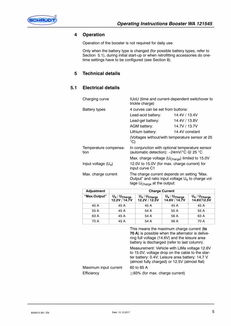
Max. charge current The charge current depends on setting ”Max.Output” and ratio input voltage Ue to charge vol-tage UCharge at the output:
Adjustment Charge Current
”Max.Output” Ue / UCharge12.2V / 14.7V
Ue / UCharge12.2V / 12.5V
Ue / UCharge14.6V / 14.7V
Ue / UCharge14.6V/12.5V
45 A 45 A 45 A 45 A 45 A
55 A 45 A 54 A 55 A 55 A
63 A 45 A 54 A 56 A 63 A
70 A 45 A 54 A 56 A 70 A
This means the maximum charge current (to70 A) is possible when the alternator is delive-ring full voltage (14.6V) and the leisure areabattery is discharged (refer to last column).Measurement: Vehicle with LiMa voltage 12.6Vto 15.0V; voltage drop on the cable to the star-ter battery: 0.4V; Leisure area battery: 14,7 V(almost fully charged) or 12.5V (almost flat)
Maximum input current 60 to 65 AEfficiency ²93% (for max. charge current)

Operating Instructions Booster WA 121545
6 Date: 12.12.2017 8200510 BA / EN
Charge current limitation Specified by power limitation characteristics C1to C4. The maximum charge current is reachedfor the following voltages:
”PowerReduct.”
No char-ging when
Max. chargecurrent
Suitable for (recommendation):
C1 Ue± 11.2V Ue² 11.8V Without input voltage sensor:EURO6-Generator with drop down voltage Uab ² 12,6 V
C2 Ue± 11.8V Ue² 12.4V With input voltage sensor:EURO6-Generator with drop down voltage Uab ² 12,6 V
C3 Ue± 12.0V Ue² 12.6V With input voltage sensor:EURO6-Generator with drop down voltage Uab ² 12,6 8 Mediumloading of the starter battery circuit
C4 Ue± 12.6V Ue² 13.2V With input voltage sensor:Conventional generator, low loading of the starter battery circuit
Power limitation characteristics C1 to C4:
IL (A)
0UE (V)10 10,5 11 11,5
Imax
C1
C2
C3
C4
12 12,5 1311,2 11,8 12,6 13,2
11,8 12,4 12,6 13,2
Fig. 1 Charge current limitation characteristics C1 to C4
Back current from battery(after cooling)
”Engine OFF”: Starter battery: < 0.1 mALeisure area battery: <0.2mA
Control current ”Engine ON”: D+ connector: < 1mA
5.2 Mechanical details
Connections Batteries: SPC16- or ISPC16 Phoenix plugconnector for connecting wires tomax. 16mm2 (connector with ten-sion clamps)
D+Connector:
Rast 5; code 0G; 2-pin or 6.3 mmAMP flat connector
SDTBUS 2 Lumberg pin railsType MSFQ, each 3-pin
Tempera-ture sensor:
SB: VAL-U-LOK; 2-pinWB: VAL-U-LOK; 4-pinType Tyco AMP 2-pin / 4-pin
Casing Aluminium, 160 x 79 x 160 mm(W x H x D, without attachment feed);can be screwed to flat surface(D = 186 mm including attachment feet)
Weight Approx.1,150 g
Installation position see Section 6 (Installation)

Operating Instructions Booster WA 121545
7Date: 12.12.20178200510 BA / EN
6 Installation
The device is designed for wall or floor installation.
" Select a dry place for installation.
" Ensure a minimum clearance to the surrounding fixtures and fittings:
F Maintain a gap of at least 5 cm on all sides (except mounted side).
F Keep a gap of at least 80 mm at the front (projection).
F Whilst in operation, the ambient temperature must not exceed +45 C,measured 1cm away from the fans opposite side of the device.
(137)
(11,5)
160
7
174
5.5(4x)160
(174)
186
(7)
(6)
13711.5
186
6
79
67.5
13
Fig. 2 Dimensional diagram for WA 121545 Booster (the numbers in brackets are for alter-native installation
of the attachment feet)
Y The attachment feet are either on the side or fitted down/upwards depen-ding on variant. This gives a hole pattern of 174 mm x 137 mm (horizon-tal alignment as in Figure 2) or 137 mm x 174 mm (vertical alignment).
" Use the four screws (hole diameter 4 mm, screw diameter max. 3.5 mm)to screw the Booster onto a firm, flat base at the four fitting holes provi-ded.
Environment
Minimum clearance
Fitting

Operating Instructions Booster WA 121545
8 Date: 12.12.2017 8200510 BA / EN
7 Electrical connection
The connection scenario in the vehicle must be known before the booster isintegrated into it. A distinction between the following scenarios is required:
F Vehicles with Schaudt EBL ..., for which the ground cables to bothbatteries on the EBL ... are accessible individually. Refer also to Sec-tion 7.2.
Y The connection shown in Section 7.2 is the preferred scenario for bestpossible distribution of currents.
F Vehicles with Schaudt EBL ..., for which the ground connection bet-ween the two batteries is in the vehicle itself, and only a single groundcable is connected to the EBL ....: This single ground cable is usuallyconnected at an inaccessible place at the vehicle-side ground connec-tion of the two batteries. Refer for this to Section 7.2 below.
F Vehicles with Schaudt EBL ... with SDTBUS. Refer also to Section7.3.
F Vehicles with power supplies from other manufacturers. Here the boo-ster is connected directly to the batteries and a D+ signal. Refer alsoto Section 7.4.
Y DANGER!The different connection scenarios have a direct bearing on the maximumcurrents possible, and so the fusing required. The fusing values specifiedmay never be exceeded.
Y DANGER!Every fuse must be connected in the direct vicinity of the voltage source(so the respective battery or terminal D+ on the generator).
Y The temperature sensor also shown in the figures is available an an op-tion. When this sensor is connected, charging of the leisure area batteryconnected is controlled depending on the temperature of the leisure areabattery.
Procedure
The main procedure is essentially the same for all three connection variants:
" Fully disconnect both batteries (remove all cables from both terminals).
" Establish all cable connections as in Figure 6, 7 or 8. Ensure the cableshave the cross sections required and that the fuses are installed cor-rectly. Do not yet insert the fuses into the sockets.
Y ATTENTION!Ensure the plug connectors (not included) are readied properly for connec-ting the batteries to the booster.
" Connect the battery temperature sensor (if available) for the two batteriesto the negative terminal of the respective battery.
" Reconnect the battery terminals of both batteries.
" Finish off as described in Section 7.7.
" Set the battery type (see Section 8.4).
Operating Instructions Booster WA 121545
9Date: 12.12.20178200510 BA / EN
7.1 Connection sets
Various connection kits are available to connect the booster, which meet dif-ferent requirements. All parts are included -- except the cables -- that arerequired.
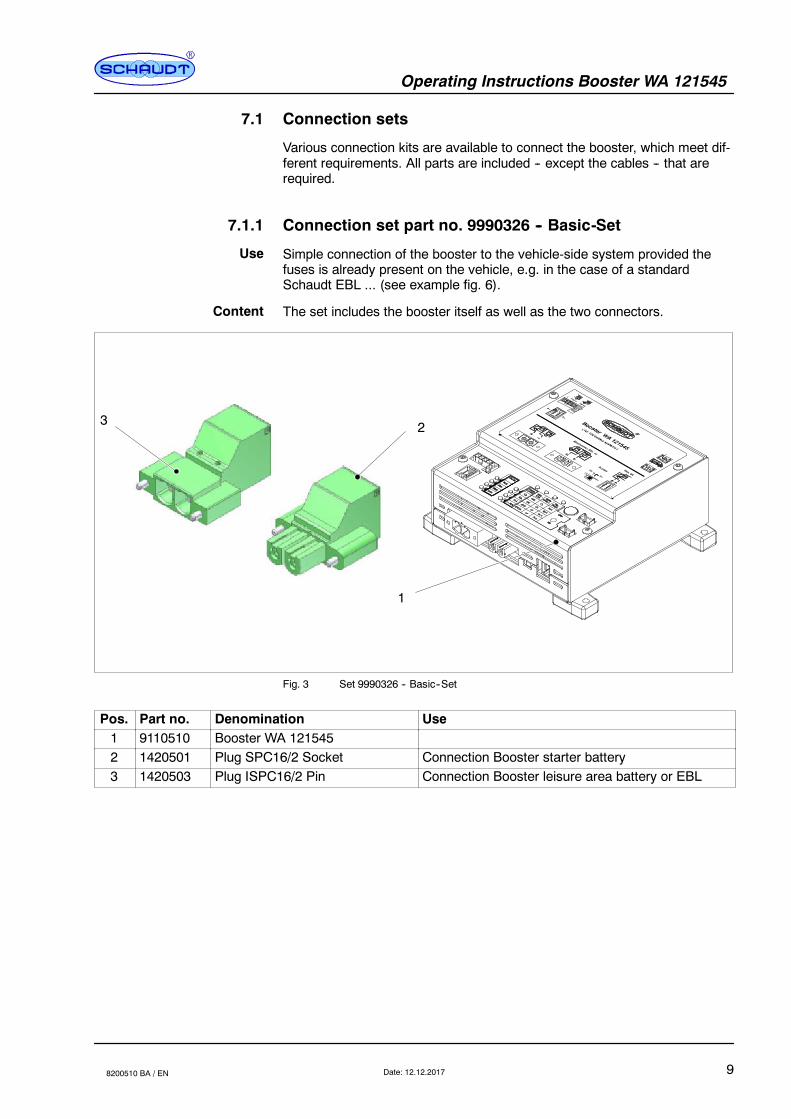
7.1.1 Connection set part no. 9990326 -- Basic-Set
Simple connection of the booster to the vehicle-side system provided thefuses is already present on the vehicle, e.g. in the case of a standardSchaudt EBL ... (see example fig. 6).
The set includes the booster itself as well as the two connectors.
3 2
1
Fig. 3 Set 9990326 -- Basic--Set
Pos. Part no. Denomination Use1 9110510 Booster WA 1215452 1420501 Plug SPC16/2 Socket Connection Booster starter battery3 1420503 Plug ISPC16/2 Pin Connection Booster leisure area battery or EBL
Use
Content
Operating Instructions Booster WA 121545
10 Date: 12.12.2017 8200510 BA / EN
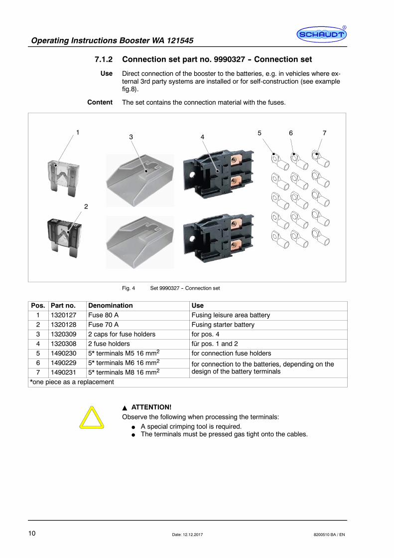
7.1.2 Connection set part no. 9990327 -- Connection set
Direct connection of the booster to the batteries, e.g. in vehicles where ex-ternal 3rd party systems are installed or for self-construction (see examplefig.8).
The set contains the connection material with the fuses.
2
31 5 6 74
Fig. 4 Set 9990327 -- Connection set
Pos. Part no. Denomination Use1 1320127 Fuse 80 A Fusing leisure area battery2 1320128 Fuse 70 A Fusing starter battery3 1320309 2 caps for fuse holders for pos. 44 1320308 2 fuse holders für pos. 1 and 25 1490230 5* terminals M5 16 mm2 for connection fuse holders6 1490229 5* terminals M6 16 mm2 for connection to the batteries, depending on the7 1490231 5* terminals M8 16 mm2
for connection to the batteries, depending on thedesign of the battery terminals
*one piece as a replacement
Y ATTENTION!Observe the following when processing the terminals:
F A special crimping tool is required.F The terminals must be pressed gas tight onto the cables.
Use
Content

Operating Instructions Booster WA 121545
11Date: 12.12.20178200510 BA / EN
7.1.3 Connection Set part no. 9990328 -- Sensor set
Extension of the functions of the booster:
F Temperature controlled charging
F Charge with compensation of the voltage drop across the leisure areabattery line
The set includes two cable sets with leads for a voltage sensor (the cable tothe leisure area battery also contains a temperature sensor) and connectionmaterial with fuse.
1
2
3
4
5
6
Fig. 5 Set 9990328 -- Sensors with connection parts
Pos. Part no. Denomination Use1 9000110 Sensor cable leisure area battery
M6Voltage and temperature sensor
2 9340225 Sensor starter battery M6 Voltage sensor3 1320091 2 caps for fuse holders for pos. 1 and 24 1320092 2 mounting brackets for fuse hol-
dersfor pos. 1 and 2
5 1320151 2 fuses 1 A Fusing cables voltage sensor pos. 1 and 26 1490204 4 terminals M8 Alternative for the connection of the voltage sensors
7.1.4 Connection set part no. 9990333 -- Complete set
Complete installations in larger mobile homes.
The set includes all parts from the above sets.
Use
Content
Use
Content

Operating Instructions Booster WA 121545
12 Date: 12.12.2017 8200510 BA / EN
7.2 Booster connector for standard EBLs -- grounds of bothbatteries on the booster
To D+ input onEBL ...
(engine running-- Lima signal)
Battery 1
+ --
Battery 2
+ --
70 A
Temperature and voltage sensor
Leisure areabattery
Starterbattery
EBL ...Battery connectors
(rear)
EBL ...(example: EBL 30, otherEBLs also possible)D+ connector
(front)
2 A
GD+
B--B+
Generator
50 -- 60 A
16mm2
10...16
mm2
10...16
mm2
16mm2
16mm2
10...16
mm2
0.75
mm2
0.75
mm2
Voltage sensor
”Bypass” switch in ”Off”
position (see Section 8.4.4)
Also remember the fuse on the
vehicle side.Set the maximum output current(”Max. Output”) to ”45 A” or ”55
A” (see Section 8.4.3).
1 A1 A
Fig. 6 Vehicles with Schaudt EBL ... -- ground on booster
For vehicles in which the cabling can be as shown in Figure 7, the groundconnection on the booster between the leisure area battery and the starterbattery is an absolute requirement. The two batteries may not be directlyconnected (e.g. inside the vehicle’s cabling). If they are, the cable betweenthe leisure area battery and the booster is redundant.
Y ATTENTION!The ground cable between the EBL and the leisure area battery (battery 2)must have a cross section of 16 mm2 (no smaller).
Operating Instructions Booster WA 121545
13Date: 12.12.20178200510 BA / EN
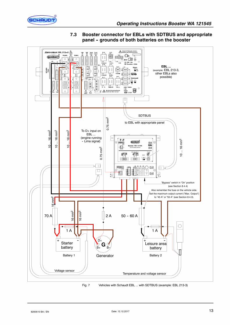
7.3 Booster connector for EBLs with SDTBUS and appropriatepanel -- grounds of both batteries on the booster
To D+ input onEBL ...
(engine running-- Lima signal)
Battery 1
+ --
Battery 2
+ --
70 A
Leisure areabattery
Starterbattery
EBL ...(example: EBL 213-3,other EBLs also
possible)
2 A
GD+
B--B+
Generator
50 -- 60 A
10...16
mm2
10...16
mm2
16mm2
16mm2
10...16
mm2
0.75
mm2
0.75
mm2
10...16
mm2
16mm2
SDTBUS
to EBL with appropriate panel
”Bypass” switch in ”On” position
(see Section 8.4.4)
Also remember the fuse on the vehicle side.
Set the maximum output current (”Max. Output”)to ”45 A” or ”55 A” (see Section 8.4.3).
Temperature and voltage sensorVoltage sensor
1 A 1 A
Fig. 7 Vehicles with Schaudt EBL ... with SDTBUS (example: EBL 213-3)
Operating Instructions Booster WA 121545
14 Date: 12.12.2017 8200510 BA / EN
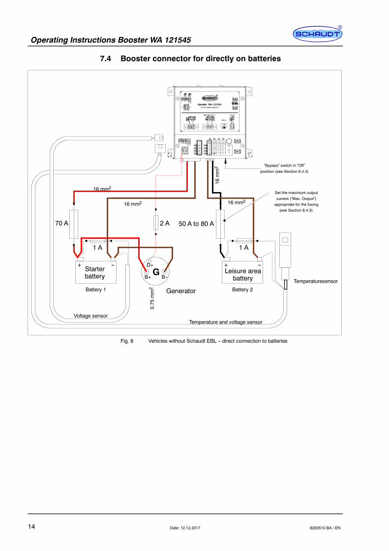
7.4 Booster connector for directly on batteries
Battery 1
+ --
Battery 2
+ --
70 A
Temperaturesensor
Leisure areabattery
Starterbattery
2 A
GD+
B--B+
Generator
50 A to 80 A
16 mm2
0.75
mm2
16 mm2 16 mm2
16mm2
Temperature and voltage sensorVoltage sensor
”Bypass” switch in ”Off”
position (see Section 8.4.4)
Set the maximum output
current (”Max. Output”)appropriate for the fusing
(see Section 8.4.3).
1 A 1 A
Fig. 8 Vehicles without Schaudt EBL -- direct connection to batteries
Operating Instructions Booster WA 121545
15Date: 12.12.20178200510 BA / EN
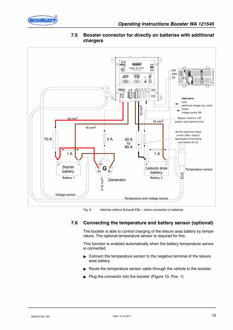
7.5 Booster connector for directly on batteries with additionalchargers
Battery 1
+ --
Battery 2
+ --
70 A
Temperature sensorLeisure areabattery
Starterbattery
2 A
GD+
B--B+
Generator
50 A
16 mm2
0.75
mm2
16 mm2
16 mm2
16mm2
Temperature and voltage sensorVoltage sensor
”Bypass” switch in ”Off”
position (see Section 8.4.4)
Set the maximum output
current (”Max. Output”)appropriate for the fusing
(see Section 8.4.3).
1 A 1 A
to80 A
+ WB
-- GND+ SB
Alternative:
Inputadditional charger (e.g. solar)Output
Voltage sensor SB
Fig. 9 Vehicles without Schaudt EBL -- direct connection to batteries
7.6 Connecting the temperature and battery sensor (optional)
The booster is able to control charging of the leisure area battery by tempe-rature. The optional temperature sensor is required for this.
This function is enabled automatically when the battery temperature sensoris connected.
" Connect the temperature sensor to the negative terminal of the leisurearea battery.
" Route the temperature sensor cable through the vehicle to the booster.
" Plug the connector into the booster (Figure 10, Pos. 1).

Operating Instructions Booster WA 121545
16 Date: 12.12.2017 8200510 BA / EN
1 2 3 4 (GND)
Sensor forleisure area battery
Temperature sensor forleisure area battery
+ --
+
--
BatterysensorStarterbattery
1
2
Fig. 10 Temperature sensor: Connection
" Connect the battery sensor cables to the leisure area and starter batte-ries.
" Connect the battery sensor cables to the booster as in Figure 10.
Y If voltage sensor cables and the temperature sensor are connected, thesettings required for the evaluation of the measuring signals are perfor-med automatically in the booster.Therefore, the battery voltage sensor cables may only be connected tothe booster. A loop from the booster to other devices, or a tap of the si-gnal between the fuse and the booster is not permissible.
Y ATTENTION!If the cables of the voltage sensor for the leisure area battery are connectedincorrectly or with the wrong polarity:
F the booster has no function.
F a current of about 40 mA flows continually from the starter battery.The battery will discharche.
F a current of about 80 mA flows continually from the leisure area bat-tery. So if the vehicle remains stationary, the battery will dischargetotally and might suffer damage as a result.
Y If sensor cables and the temperature sensor are connected, the settingsin the booster required to interpret the measurement signals are configu-red automatically.
7.7 Finishing installation work
Y ATTENTION!The 10 mm2 and 16 mm2 cables to the batteries are relatively heavy andpotentially exert high loading on the plug connectors.
" The cables must be secured with suitable strain relief so that no high ten-sile forces or pressure loads are exerted onto the plug connectors of thebooster.
" Insert the fuses into the fuse holders (refer to Sections 7.2 to 7.4 for thefuse ratings).
" Fix the locking screw of both high current plugs (”starter battery” and “lei-sure area battery” connections).

Operating Instructions Booster WA 121545
17Date: 12.12.20178200510 BA / EN
8 Adjustments
8.1 Control and display panel
1
2
4
3
Fig. 11 Control and display panel for adjustments and display
1 ”Display” button (Disp.)2 ”Set” button (with sticker over it when delivered)3 ”Adjustments” display panel4 ”Charge and device status” display panel
The functions of the control and display panel:
F Display of the current charge and device statuses (Figure 11, Pos. 4),charge cycle and charge current
F On request, display of the current settings (Figure 11, Pos. 3)Battery type ”Batt. Type”, power reduction characteristic ”Power Re-duct.” and maximum possible output current ”Max. Output”
F Change settings
Y ATTENTION!Before initial use, the conditions in the vehicle must be determinedand taken into account (fuse and cable cross sections). The installa-tion of the boosters requires expert knowledge in the field of vehicleand suspension electronics.In case of doubt, the booster should be installed by a qualified specia-list company.
Y Default settings when delivered:
Part no. Batt.-Type Power reduct. Max. Output
9200510 Acid C1 (Power limitationcharacteristic 1) 45 A
9200512 AGM C3 (Power limitationcharacteristic 3) 70 A
Y ATTENTION!To change the settings, use a sharp object made of insulting material (suchas a toothpick) to pierce the gummed label above the ”Set” button inside thecircle, and use it to press the button behind.

Operating Instructions Booster WA 121545
18 Date: 12.12.2017 8200510 BA / EN
8.2 Meaning of the display
When the booster starts up (this is automatic when the vehicle engine starts,D+ is then applied to the booster), the following information is displayed bythe LEDs:
F Current charge cycle
F Fault
F Current charge current
The fields in the two columns with bold borders have the following meanings:
Charge Charge current
Main charge Risen above 1 AThe display for the charge
Full charge Risen above 3 AThe display for the chargecurrent is only a roughguide
Trickle charge Risen above 10 Aguide.
Error Risen above 30 A
8.3 Displaying current settings
The current settings are displayed using the 4 x 4 matrix on the top of thedevice (Figure 11, Pos. 3). The top LED line specifies which value it is. Theleft LED column next to the matrix shows which value is currently set.
Y The charge current is displayed during normal operation. The followingqueries are possible when the vehicle engine is running or stationary.
Proceed as follows to display the other values currently set:
" Briefly press the ”Display” (Disp.) button -- Figure 11, Pos. 1.
F The LED above the ”Batt. Type” column lights.
F One of the LEDs in the left-hand column lights, e.g. the top LED.This means that battery type ”Acid” (so lead-acid) is set.
" Briefly press the ”Display” (Disp.) button again -- Figure 11, Pos. 1.
F The LED above the ”Power Reduct.” column lights.
F One of the LEDs in the left-hand column lights, e.g. the second LEDfrom the top. This means that characteristic C2 is set (refer to Figure12 for more information on characteristics).
" Briefly press the ”Display” (Disp.) button again -- Figure 11, Pos. 1.
F The LED above the ”Max. Output” column lights.
F One of the LEDs in the left-hand column lights, e.g the lower LED.This means the maximum charge current can rise to 70 A.
”Batt. Type”
”Power Reduct.”
”Max. Output”

Operating Instructions Booster WA 121545
19Date: 12.12.20178200510 BA / EN
8.4 Adjusting the booster
8.4.1 Setting the battery type, ”Batt. Type”
Y ATTENTION!Incorrectly setting the device or using unsuitable leisure area battery typescan damage the battery or devices connected to the leisure area battery. Sotherefore:
F Only ever have batteries changed by qualified personnel
F Follow the battery manufacturer’s instructions.
F Only use the booster to connect to 12V power supplies with rechar-geable 6 cell lead-gel, lead-acid, AGM batteries or lithium batteries.Do not use any unsuitable battery types.
Y Normally only batteries of the same type and rating should be used, i.e.the same as those originally installed by the manufacturer.It is possible to swap from lead-acid batteries to other battery types. Swit-ching to lead-acid batteries is only possible in certain circumstances.Contact the vehicle manufacturer for more information.
Y Once the battery has been changed, check again which battery type hasbeen inserted and then ensure the battery type is set correctly.
Y DANGER!Incorrectly setting the battery type poses a risk of explosion (through theformation of detonating gas).
" Turn off the vehicle engine.
" Briefly press the ”Display” (Disp.) button -- Figure 11, Pos. 1.
F The LED above the ”Batt. Type” column lights.
F The LED of the battery type currently set lights in the left-hand co-lumn.
" Within 6 seconds, press the ”Set” button (Figure 11, Pos. 2) for longerthan 3 seconds.
F The LED above the ”Batt. Type” column flashes.
F The LED of the battery type currently set flashes in the left-hand co-lumn.
" Keep pressing the ”Set” button (Figure 11, Pos. 2) until the LED of thebattery type required flashes:
Batterytype used Charge voltage
Trickle chargevoltage
Max.time phase
Switchover cur-rent for
trickle charge(delayed)
Lead-acid batteries 14.4 V 13.4 V 4 hours Approx. 2.5 A
Lead-gel batteriesAGM1 batteries 14.4 V 13.8 V 8 hours Approx. 2.5 A
AGM2 batteries 14.7 V 13.7 V 4 hours Approx. 2.5 A
Lithium batteries 14.4 V constant (Curve CCCV)*
Voltage values apply when no temperature sensor is connectedor (with temperature sensor) at 25 C
* Only LiFePo4 batteries may be charged which have their own battery management system.
Changing the battery
Setting
Operating Instructions Booster WA 121545
20 Date: 12.12.2017 8200510 BA / EN
" Press the ”Set” button (Figure 11, Pos. 2) for longer than 3 seconds.
F The LED of the newly set battery type lights permanently.
F The newly set battery type is saved.
Y ATTENTION!Once the setting is complete, check as in Section 8.3 whether the settingshave been completed correctly.
8.4.2 Setting the ”Power Reduct.” characteristic C1 ... C4
Y ATTENTION!The correct characteristic selection is dependent on the generator available.So therefore:
F check before adjusting the setting which generator type is fitted in thevehicle (consult with the chassis manufacturer if required)
F The corresponding characteristic defines the lower voltage thresholdfrom which no more charging takes place (i.e. no more current isdrawn from the generator), and the upper voltage value from whichthe maximum charge current can flow (into the leisure area battery).
" Turn off the vehicle engine.
" Keep pressing the ”Display” (Disp.) button (Figure 11, Pos. 1) until theLED above the ”Power Reduct.” column lights.
F The LED above the ”Power Reduct.” column lights.
F Lighting in the left-hand column is the LED of curve C1 to C4 currentlyset (Characteristic 1 ... 4).
" Within 6 seconds, press the ”Set” button (Figure 11, Pos. 2) for longerthan 3 seconds.
F The LED above the ”Power Reduct.” column flashes.
F The LED of curve C1 to C4 currently set (Characteristic 1 ... 4) flas-hes.
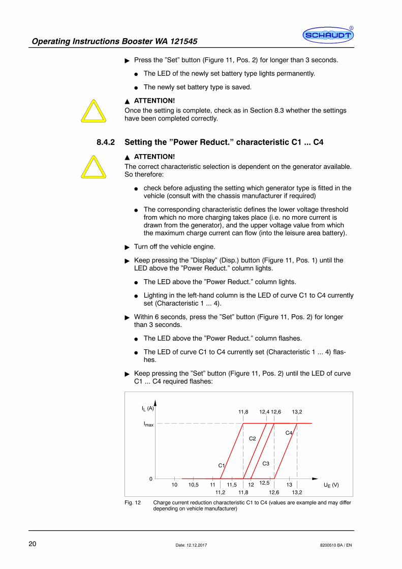
" Keep pressing the ”Set” button (Figure 11, Pos. 2) until the LED of curveC1 ... C4 required flashes:
IL (A)
0UE (V)10 10,5 11 11,5
Imax
C1
C2
C3
C4
12 12,5 1311,2 11,8 12,6 13,2
11,8 12,4 12,6 13,2
Fig. 12 Charge current reduction characteristic C1 to C4 (values are example and may differdepending on vehicle manufacturer)

Operating Instructions Booster WA 121545
21Date: 12.12.20178200510 BA / EN
" Press the ”Set” button (Figure 11, Pos. 2) for longer than 3 seconds.
F The LED of the newly set curve lights.
F The newly set curve is saved.
Y Recommendations:
F C1: EURO6-Generator without input voltage sensor
F C2: EURO6-Generator with input voltage sensor
F C3: Medium loading of the starter battery circuit with input voltagesensor
F C4: Low loading of the starter battery circuit with input voltage sensor
8.4.3 Setting the maximum output current, ”Max. Output”
" Turn off the vehicle engine.
" Keep pressing the ”Display” (Disp.) button (Figure 11, Pos. 1) until theLED above the ”Max. Output” column lights.
F The LED above the ”Max. Output” column lights.
F The LED of the maximum current currently set lights in the left-handcolumn.
" Within 6 seconds, press the ”Set” button (Figure 11, Pos. 2) for longerthan 3 seconds.
F The LED above the ”Max. Output” column flashes.
F The LED of the maximum current currently set flashes.
" Keep pressing the ”Set” button (Figure 11, Pos. 2) until the LED of themaximum charge current required (45, 55, 63 or 70 A) flashes:
" Press the ”Set” button (Figure 11, Pos. 2) for longer than 3 seconds.
F The LED of the newly set maximum current lights.
F The newly set maximum current is saved.
Y DANGER!The fuse and cabling on the output side must be designed for the maxi-mum charge current set. Otherwise the battery fuse will keep tripping or,for too high a fuse rating and too low a cable cross section, a cable fire willresult (also refer to Section 7).
Operating Instructions Booster WA 121545
22 Date: 12.12.2017 8200510 BA / EN
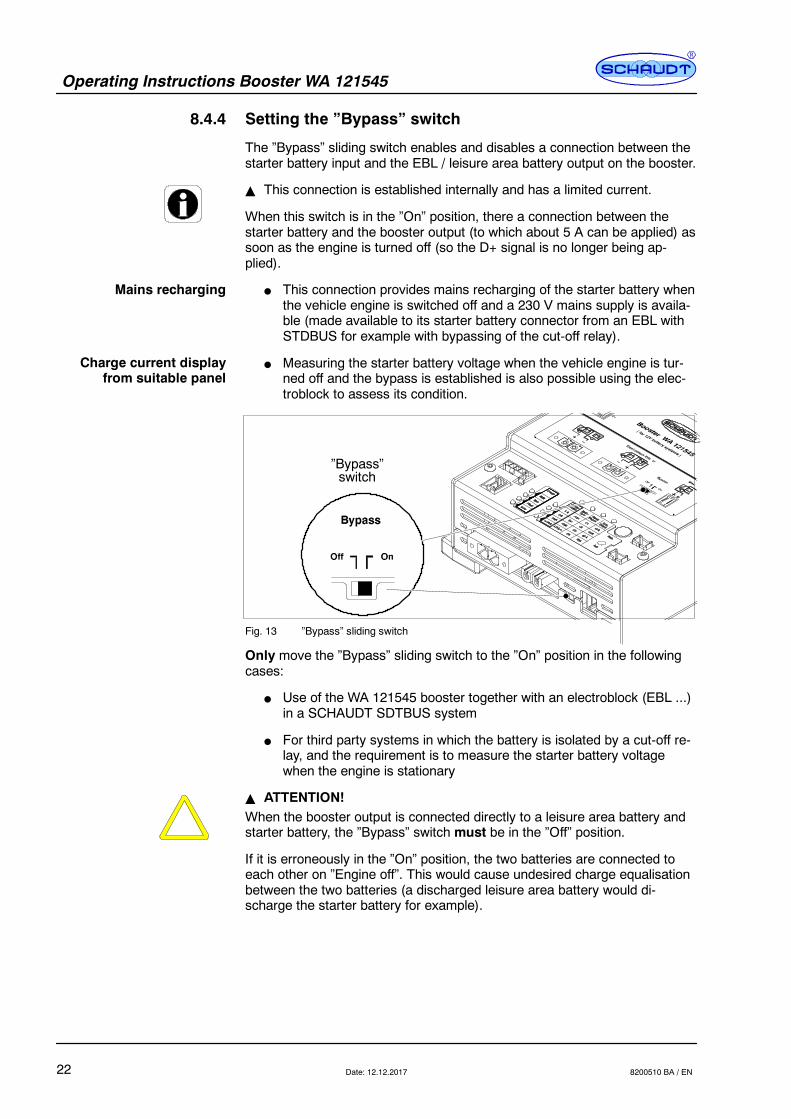
8.4.4 Setting the ”Bypass” switch
The ”Bypass” sliding switch enables and disables a connection between thestarter battery input and the EBL / leisure area battery output on the booster.
Y This connection is established internally and has a limited current.
When this switch is in the ”On” position, there a connection between thestarter battery and the booster output (to which about 5 A can be applied) assoon as the engine is turned off (so the D+ signal is no longer being ap-plied).
F This connection provides mains recharging of the starter battery whenthe vehicle engine is switched off and a 230 V mains supply is availa-ble (made available to its starter battery connector from an EBL withSTDBUS for example with bypassing of the cut-off relay).
F Measuring the starter battery voltage when the vehicle engine is tur-ned off and the bypass is established is also possible using the elec-troblock to assess its condition.
”Bypass”switch
Fig. 13 ”Bypass” sliding switch
Only move the ”Bypass” sliding switch to the ”On” position in the followingcases:
F Use of the WA 121545 booster together with an electroblock (EBL ...)in a SCHAUDT SDTBUS system
F For third party systems in which the battery is isolated by a cut-off re-lay, and the requirement is to measure the starter battery voltagewhen the engine is stationary
Y ATTENTION!When the booster output is connected directly to a leisure area battery andstarter battery, the ”Bypass” switch must be in the ”Off” position.
If it is erroneously in the ”On” position, the two batteries are connected toeach other on ”Engine off”. This would cause undesired charge equalisationbetween the two batteries (a discharged leisure area battery would di-scharge the starter battery for example).
Mains recharging
Charge current displayfrom suitable panel
Operating Instructions Booster WA 121545
23Date: 12.12.20178200510 BA / EN
9 Initial use
The booster is switched on automatically as soon as the vehicle engine isstarted.
" Check the following before trying to start the first time:
F Are all the plug connectors secure?
F Are all the cables connected with the right polarity?
F Are all the cables secured correctly in the tension clamps?
F Are the cables adequately secured?
F Are all the settings correct as per the requirements?
-- Correct battery type set (”Batt. Type”)-- Is the power reduction characteristic suitable for the generator
(”Power Reduct.”)?-- Is the maximum current appropriate for the fusing (Max. Output”)?
" Start the engine.
" Check the booster display:
F Is a charge mode displayed?
F Is LED ”Error” off?
Y ATTENTION!If the ”Error” LED lights or nothing is displayed, check the cabling and thesettings.
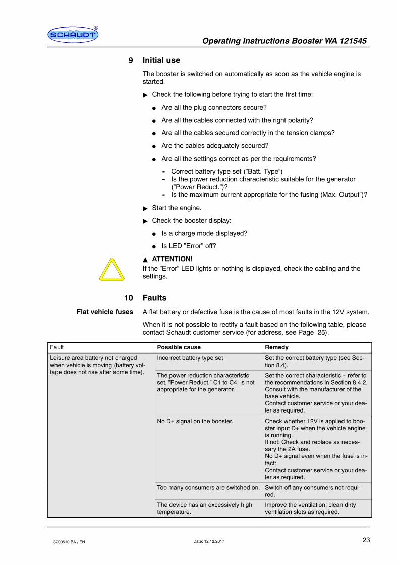
10 Faults
A flat battery or defective fuse is the cause of most faults in the 12V system.
When it is not possible to rectify a fault based on the following table, pleasecontact Schaudt customer service (for address, see Page 25).
Fault Possible cause Remedy
Leisure area battery not chargedwhen vehicle is moving (battery vol-t d t i ft ti )
Incorrect battery type set Set the correct battery type (see Sec-tion 8.4).g ( y
tage does not rise after some time). The power reduction characteristicset, ”Power Reduct.” C1 to C4, is notappropriate for the generator.
Set the correct characteristic -- refer tothe recommendations in Section 8.4.2.Consult with the manufacturer of thebase vehicle.Contact customer service or your dea-ler as required.
No D+ signal on the booster. Check whether 12V is applied to boo-ster input D+ when the vehicle engineis running.If not: Check and replace as neces-sary the 2A fuse.No D+ signal even when the fuse is in-tact:Contact customer service or your dea-ler as required.
Too many consumers are switched on. Switch off any consumers not requi-red.
The device has an excessively hightemperature.
Improve the ventilation; clean dirtyventilation slots as required.
Flat vehicle fuses
Operating Instructions Booster WA 121545
24 Date: 12.12.2017 8200510 BA / EN
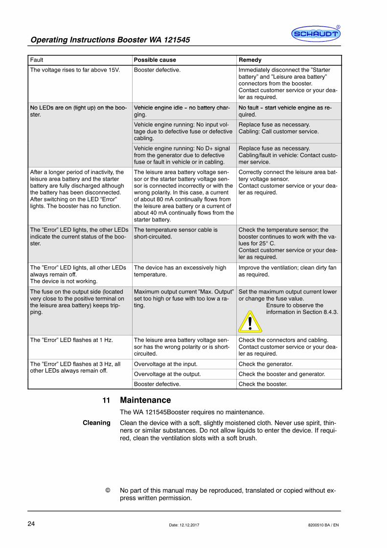
Fault RemedyPossible cause
The voltage rises to far above 15V. Booster defective. Immediately disconnect the ”Starterbattery” and ”Leisure area battery”connectors from the booster.Contact customer service or your dea-ler as required.
No LEDs are on (light up) on the boo- Vehicle engine idle -- no battery char- No fault -- start vehicle engine as re-No LEDs are on (light up) on the boo-ster
Vehicle engine idle -- no battery char-ging
No fault -- start vehicle engine as re-quiredster. ging. quired.
Vehicle engine running: No input vol-tage due to defective fuse or defectivecabling.
Replace fuse as necessary.Cabling: Call customer service.
Vehicle engine running: No D+ signalfrom the generator due to defectivefuse or fault in vehicle or in cabling.
Replace fuse as necessary.Cabling/fault in vehicle: Contact custo-mer service.
After a longer period of inactivity, theleisure area battery and the starterbattery are fully discharged althoughthe battery has been disconnected.After switching on the LED “Error”lights. The booster has no function.
The leisure area battery voltage sen-sor or the starter battery voltage sen-sor is connected incorrectly or with thewrong polarity. In this case, a currentof about 80 mA continually flows fromthe leisure area battery or a current ofabout 40 mA continually flows from thestarter battery.
Correctly connect the leisure area bat-tery voltage sensor.Contact customer service or your dea-ler as required.
The ”Error” LED lights, the other LEDsindicate the current status of the boo-ster.
The temperature sensor cable isshort-circuited.
Check the temperature sensor; thebooster continues to work with the va-lues for 25 C.Contact customer service or your dea-ler as required.
The ”Error” LED lights, all other LEDsalways remain off.The device is not working.
The device has an excessively hightemperature.
Improve the ventilation; clean dirty fanas required.
The fuse on the output side (locatedvery close to the positive terminal onthe leisure area battery) keeps trip-ping.
Maximum output current ”Max. Output”set too high or fuse with too low a ra-ting.
Set the maximum output current loweror change the fuse value.
Ensure to observe theinformation in Section 8.4.3.
The ”Error” LED flashes at 1 Hz. The leisure area battery voltage sen-sor has the wrong polarity or is short-circuited.
Check the connectors and cabling.Contact customer service or your dea-ler as required.
The ”Error” LED flashes at 3 Hz, allth LED l i ff
Overvoltage at the input. Check the generator.other LEDs always remain off. Overvoltage at the output. Check the booster and generator.
Booster defective. Check the booster.
11 MaintenanceThe WA 121545Booster requires no maintenance.
Clean the device with a soft, slightly moistened cloth. Never use spirit, thin-ners or similar substances. Do not allow liquids to enter the device. If requi-red, clean the ventilation slots with a soft brush.
No part of this manual may be reproduced, translated or copied without ex-press written permission.
Cleaning
E
Operating Instructions Booster WA 121545
25Date: 12.12.20178200510 BA / EN
Appendix
A Customer service
Schaudt GmbH, Elektrotechnik & ApparatebauPlanckstraße 888677 Markdorf, Germany
Phone: +49 7544 9577-16
Email: [email protected]
Website: www.schaudt.gmbh
Y Before returning a device, we recommend taking a look at the frequentlyasked questions (FAQs) on website ”www.schaudt-gmbh.de”. This maygive you some pointers towards fault rectification, or perhaps even alsoincorrect operation.
Returning a faulty device:
" If possible: Fill in the pre-registration in the relevant area on the”www.schaudt-gmbh.de” website.
" Fill in and enclose the fault report, see Appendix B.
" Send it to the addressee (free delivery).
B Fault report
In the event of damage, please fill in the fault report and send it with thefaulty device to the manufacturer.
Device type: _______________________Item no.: _______________________Vehicle: Manufacturer: _______________________
Model: _______________________Own installation? Yes- No-Upgrade? Yes- No-
Upstream overvoltage protection? Yes- No-
Following fault has occurred (please tick):
- Electrical consumers do not work -- which?(please specify below)
- Switching on and off not possible- Persistent fault- Intermittent fault/loose contact
Other comments:
Customer service
Send in device
Operating Instructions Booster WA 121545
26 Date: 12.12.2017 8200510 BA / EN
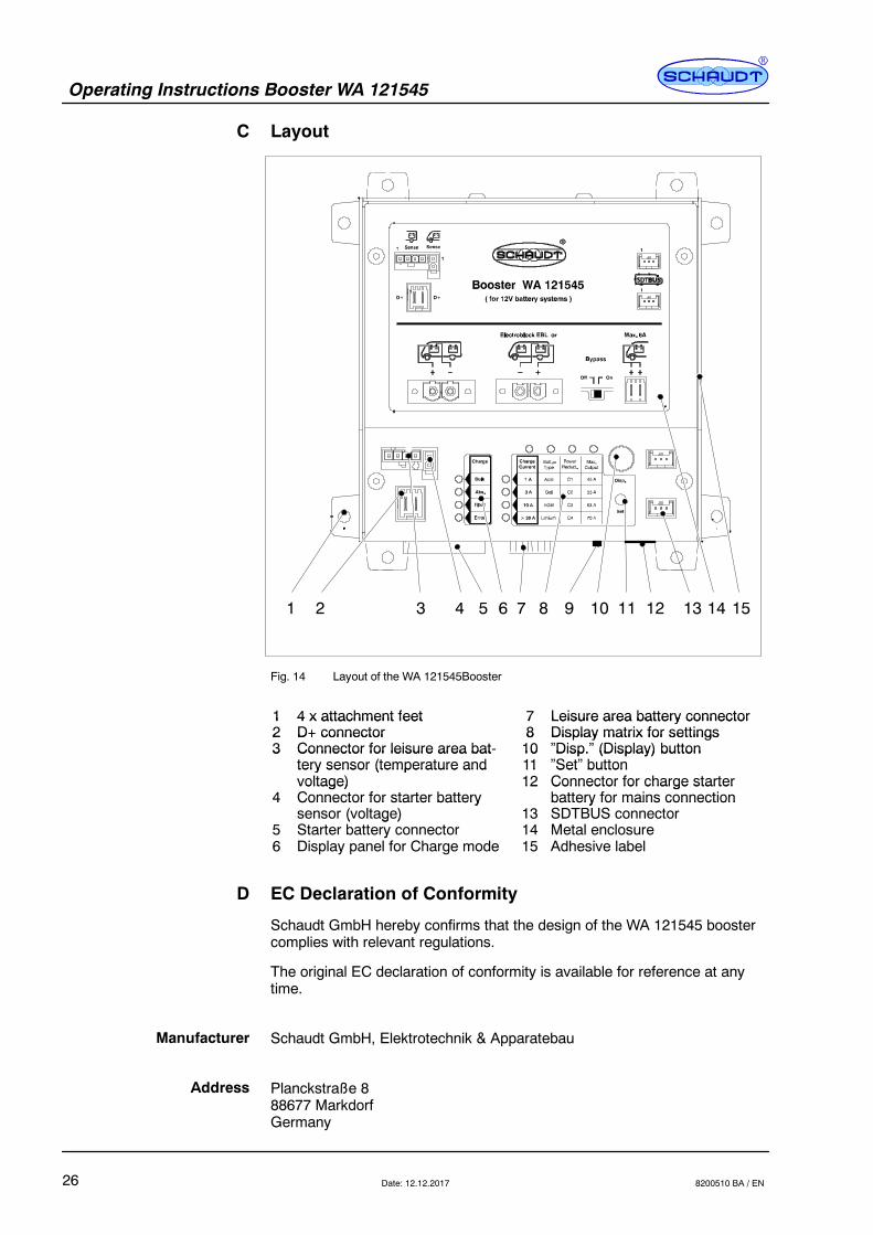
C Layout
1 2 3 4 5 6 7 8 9 10 11 12 13 1514
Fig. 14 Layout of the WA 121545Booster
1 4 x attachment feet 7 Leisure area battery connector12
4 x attachment feetD+ connector
78
Leisure area battery connectorDisplay matrix for settings2
3D+ connectorConnector for leisure area bat-
810
Display matrix for settings”Disp.” (Display) button3 Connector for leisure area bat
tery sensor (temperature and1011
Disp. (Display) button”Set” buttontery sensor (temperature and
voltage)1112
Set buttonConnector for charge starter
4voltage)Connector for starter battery
12 Connector for charge starterbattery for mains connection4 Connector for starter battery
sensor (voltage) 13battery for mains connectionSDTBUS connector
5( g )
Starter battery connector 14 Metal enclosure6
yDisplay panel for Charge mode 15 Adhesive label
D EC Declaration of Conformity
Schaudt GmbH hereby confirms that the design of the WA 121545 boostercomplies with relevant regulations.
The original EC declaration of conformity is available for reference at anytime.
Schaudt GmbH, Elektrotechnik & Apparatebau
Planckstraße 888677 MarkdorfGermany
Manufacturer
Address