air conditioning - toyota-tech.eub5b340af-9995-470b... · vehicle and air conditioning kit...
TRANSCRIPT
AAUMU-36
ENGLISH-DEUTSCH-FRANÇAIS
AIR CONDITIONING
INS
TA
LLA
TIO
N M
AN
UA
L
HFC 134aOzo
ne
Friendly Refrigerant
AAUMU-36
INS
IDE
PA
SS
EN
GE
R C
OM
PA
RT
ME
NT
/
FOR EUROPEAN SPEC. / GENERAL SPEC.

AAUMU-36
© 2000 (EUROPE) B.V..
Alle Rechte vorbehalten. Dieses Buch oder Teile davon
dürfen ohne schriftliche Genehmigung des Herausgebers
in keiner Form reproduziert oder vervielfältigt werden.
© 2000 (EUROPE) B.V..
Tous les droits sont réservés. La reproduction ou la
copie, même partielle de ce manuel est strictement
interdite sans l'autorisation de l'auteur ou de l'éditeur.
© 2000 (EUROPE) B.V..
All Rights Reserved. This book, parts thereof, may
not be reproduced or copied in any form without
the written permission of the publisher.

- 1 -
AAUMU-36
EN
GLIS
H
This manual has been designed for technicians who are qualified and educated in the proper procedures of vehicle safety,
handling and maintenance; experienced in installation of car air conditioning or who are able to carry out installation
procedures when given instructions by an experienced technician in a supervisory capacity; and are certified to handling
refrigerant.
1. Take special care to ensure that clearance between air conditioning components and other components such as brake
parts, fuel system and electric wires as specified in this manual.
2. If a problem is found with the air conditioning system due to installation, refer back to the manual to correct the
problem(s).
3. Vehicle and air conditioning kit components as well as installation procedures are subject to change without prior
notice. Refer to the latest installation manual and service information. Any changes affecting the above items will be
given in the form of an "Installation instructions for air conditioning (Supplement)" (issued by DENSO) or a service
bulletin (issued by the manufacturer).
INTRODUCTION
IMPORTANT NOTICE
FOREWORDThis manual has been published to explain how to install the air conditioning for TOYOTA AVENSIS / CORONA.
When installing the air conditioning, installation should be performed as described in this manual.
[APPLICATION VEHICLE]
VEHICLE NAME MODEL CODE PRODUCTION PERIOD STEERING POSITION
AVENSIS / CORONA 2000.07---> LHD
1. Carefully read the separate manual "GENERAL INFORMATION / AFTER INSTALLATION" before and afterinstallation.
2. Refer to the separate manual "INSTALLATION MANUAL (INSIDE ENGINE COMPARTMENT)" for details on installationfor the engine compartment side.
CAUTION
WARNING : Describes precautions that should be observed in order to prevent injury or death to the user
during installation.
CAUTION : Describes precautions that should be observed in order to prevent damage to the vehicle or its
components, which may occur during installation if insufficient care is taken.
NOTE : Provides additional information that facilitates installation work.
FRONT, REAR
LEFT, RIGHT : Shows the direction when viewed from the driver's seat
DEFINITION OF TERMS
ZZT220LZZT221LST220LAZT220LCDT220L
- 2 -
AAUMU-36
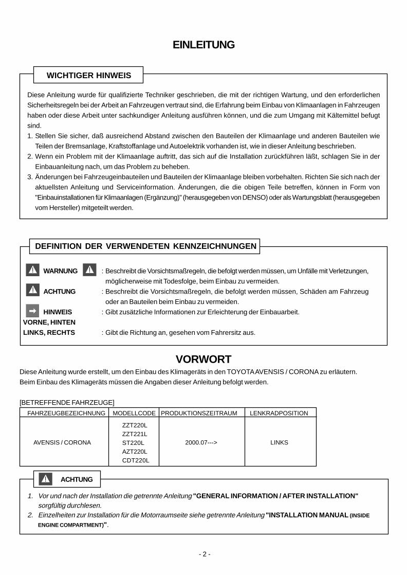
Diese Anleitung wurde für qualifizierte Techniker geschrieben, die mit der richtigen Wartung, und den erforderlichen
Sicherheitsregeln bei der Arbeit an Fahrzeugen vertraut sind, die Erfahrung beim Einbau von Klimaanlagen in Fahrzeugen
haben oder diese Arbeit unter sachkundiger Anleitung ausführen können, und die zum Umgang mit Kältemittel befugt
sind.
1. Stellen Sie sicher, daß ausreichend Abstand zwischen den Bauteilen der Klimaanlage und anderen Bauteilen wie
Teilen der Bremsanlage, Kraftstoffanlage und Autoelektrik vorhanden ist, wie in dieser Anleitung beschrieben.
2. Wenn ein Problem mit der Klimaanlage auftritt, das sich auf die Installation zurückführen läßt, schlagen Sie in der
Einbauanleitung nach, um das Problem zu beheben.
3. Änderungen bei Fahrzeugeinbauteilen und Bauteilen der Klimaanlage bleiben vorbehalten. Richten Sie sich nach der
aktuellsten Anleitung und Serviceinformation. Änderungen, die die obigen Teile betreffen, können in Form von
"Einbauinstallationen für Klimaanlagen (Ergänzung)" (herausgegeben von DENSO) oder als Wartungsblatt (herausgegeben
vom Hersteller) mitgeteilt werden.
EINLEITUNG
WICHTIGER HINWEIS
1. Vor und nach der Installation die getrennte Anleitung "GENERAL INFORMATION / AFTER INSTALLATION"sorgfültig durchlesen.
2. Einzelheiten zur Installation für die Motorraumseite siehe getrennte Anleitung "INSTALLATION MANUAL (INSIDE
ENGINE COMPARTMENT)" .
ACHTUNG
WARNUNG : Beschreibt die Vorsichtsmaßregeln, die befolgt werden müssen, um Unfälle mit Verletzungen,
möglicherweise mit Todesfolge, beim Einbau zu vermeiden.
ACHTUNG : Beschreibt die Vorsichtsmaßregeln, die befolgt werden müssen, Schäden am Fahrzeug
oder an Bauteilen beim Einbau zu vermeiden.
HINWEIS : Gibt zusätzliche Informationen zur Erleichterung der Einbauarbeit.
VORNE, HINTEN
LINKS, RECHTS : Gibt die Richtung an, gesehen vom Fahrersitz aus.
DEFINITION DER VERWENDETEN KENNZEICHNUNGEN
VORWORTDiese Anleitung wurde erstellt, um den Einbau des Klimageräts in den TOYOTA AVENSIS / CORONA zu erläutern.
Beim Einbau des Klimageräts müssen die Angaben dieser Anleitung befolgt werden.
[BETREFFENDE FAHRZEUGE]
FAHRZEUGBEZEICHNUNG MODELLCODE PRODUKTIONSZEITRAUM LENKRADPOSITION
AVENSIS / CORONA 2000.07---> LINKS
ZZT220LZZT221LST220LAZT220LCDT220L

- 3 -
AAUMU-36
FR
AN
ÇA
IS
AVERTISSEMENT : Décrit les précautions dont il faut tenir compte afin d’éviter toute blessure ou décès de
l’utilisateur pendant l’installation.
ATTENTION : Décrit les précautions dont il faut tenir compte pour éviter tout endommagement du
véhicule ou des pièces.
REMARQUE : Fournit des informations complémentaires qui facilitent le travail d’installation.
AVANT, ARRIERE
GAUCHE, DROITE : Indique le sens à partir du siège du conducteur.
DEFINITION DES TERMES
AVANT-PROPOSLe but de ce manuel est de donner les explications nécessaires pour l’installation du climatiseur dans les TOYOTA
AVENSIS / CORONA.
Lors de l’installation du climatiseur, il est indispensable de suivre exactement les instructions de ce manuel.
[VEHICULE CONCERNE]
Ce manuel a été conçu pour les techniciens qualifiés et formés dans le domaine de la sécurité automobile, l'installation et
al maintenance, ayant une expérience de l'intallation des climatiseurs auto, ou capables de les installer sous la conduite
d'un technicien expérimenté, et autorisés à manipuler le réfrigérant.
1. Prenez les précautions nécessaires pour que le jeu entre les pièces du climatiseur et les autres pièces, telles les
pièces du système de freinage, le système d'alimentation en carburant et les fils électriques, corresponde aux
spécifications indiquées dans ce manuel.
2. En cas de problème dû à l'installation du climatiseur, veuillez consulter le manuel pour résoundre le(s) problème(s).
3. Les pièces du véhicule, les pièces du kit climatiseur et les instructions d'installation peuvent être changées sans avis
préalable. Veuillez vous référer aux toutes dernières informations d'entretien et au dernier manuel d'installation. Tous
ces changements seront indiqués dans la brochure "Instructions d'installation de climatiseur (Supplément)" (publié par
DENSO) ou dans un bulletin de service (publié par le fabricant).
INTRODUCTION
NOTICE IMPORTANTE
1. Lire attentivement le manuel séparés "GENERAL INFORMATION / AFTER INSTALLATION" , avant et aprèsl'installation.
2. Pour les détails sur l'installation dans le compartment du moteur, se référer au manuel séparés "INSTALLATIONMANUAL (INSIDE ENGINE COMPARTMENT)" .
ATTENTION
NOM DE VEHICULE CODE DE MODELE PERIODE DE PRODUCTION CONDUITE
AVENSIS / CORONA 2000.07---> GAUCHE
ZZT220LZZT221LST220LAZT220LCDT220L
- 4 -
AAUMU-36
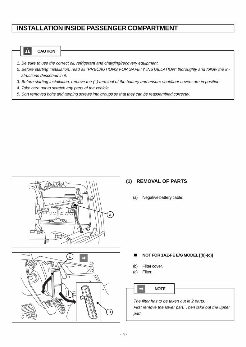
CAUTION
1. Be sure to use the correct oil, refrigerant and charging/recovery equipment.
2. Before starting installation, read all “PRECAUTIONS FOR SAFETY INSTALLATION” thoroughly and follow the in-
structions described in it.
3. Before starting installation, remove the (–) terminal of the battery and ensure seat/floor covers are in position.
4. Take care not to scratch any parts of the vehicle.
5. Sort removed bolts and tapping screws into groups so that they can be reassembled correctly.
INSTALLATION INSIDE PASSENGER COMPARTMENT
(1) REMOVAL OF PARTS
(b) Filter cover.(c) Filter.
(a) Negative battery cable.
NOTE
The filter has to be taken out in 2 parts.
First remove the lower part. Then take out the upper
part.
< NOT FOR 1AZ-FE E/G MODEL [(b)-(c)]
b
c
a

- 5 -
AAUMU-36
1. Veillez à utiliser l’huile, le réfrigérant et l’appareil de
charge/récupération corrects.
2. Avant d’entreprendre l’installation, lisez
attentivement toutes les “PRECAUTIONS DE
SECURITE” et procédez comme indiqué.
3. Avant d’entreprendre l’installation, enlevez le câble
de la cosse (-) de la batterie et recouvrez les sièges
et le sol de housses.
4. Veillez à ne rayer aucune partie de la voiture.
5. Groupez séparément les boulons et les vis
autotaradeuses de manière à les remonter
correctement.
1. Immer sicherstellen, daß die richtige Ausrüstung zum
Befüllen/Evakuieren verwendet wird.
2. Vor dem Beginn des Einbaus alle “VORSICHTS-
MASSREGELN ZUR SICHERHEIT” gründlich
durchlesen und zur Kenntnis nehmen.
3. Vor dem Einbau die negative Batterieklemme (-)
abtrennen und sicherstellen, daß alle Sitz/Boden-
Schutzabdeckungen angebracht sind.
4. Darauf achten, keine Fahrzeugteile zu zerkratzen.
5. Alle entfernten Schrauben und Blechschrauben in
Gruppen sortiert ablegen, so daß sie beim
Zusammenbau wieder korrekt verwendet werden
können.
ACHTUNG ATTENTION
EINBAU IM FAHRGASTRAUM INSTALLATION DANS LECOMPARTIMENT PASSAGER
EN
GLIS
H - D
EU
TS
CH
- FR
AN
ÇA
IS
(1) AUSBAU VON TEILEN (1) DEPOSE DES PIECES
(b) Couvercle du filtre.(c) Filtre.
(a) Câble négatif de la batterie.
(b) Filter deckel.(c) Filter.
(a) Massekabel der Batterie.
Beide teilen von den Filter ausbauen.
Zum ersten den unteren teil wegnemen. Da nach den
oberen teil.
HINWEIS
Le filtre peut être demonté en deux parties. Enlevez
d’abord la partie inférieure, puis enlevez la partie
supérieure.
REMARQUE
< NICHT FÜR 1AZ-FE E/G MODELL [(b)-(c)] < NE CONCERNE PAS LE MODELE 1AZ-FE E/G [(b)-(c)]
- 6 -
AAUMU-36
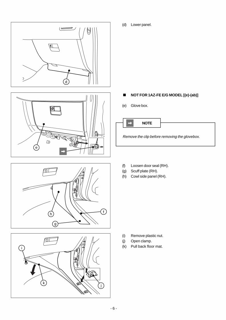
(i) Remove plastic nut.(j) Open clamp.(k) Pull back floor mat.
(f) Loosen door seal (RH).(g) Scuff plate (RH).(h) Cowl side panel (RH).
(d) Lower panel.
(e) Glove box.
NOTE
Remove the clip before removing the glovebox.
< NOT FOR 1AZ-FE E/G MODEL [(e)-(ab)]
j
h
g
d
e
f
k
i

- 7 -
AAUMU-36
EN
GLIS
H - D
EU
TS
CH
- FR
AN
ÇA
IS
(i) Plastikmutter entfernen.(j) Schelle öffnen.(k) Bodenmatte.
(i) Deposez l'écrou en plastique.(j) Ouvrez le raccord instantané.(k) Tapis de sol.
(f) Türgummi (rechts).(g) Schwellenblende (rechts).(h) Windlaufseitenblech (rechts).
(f) Joint de porte (droite).(g) Bordure de protection (droite).(h) Moulure d'allège (droite).
(d) Unterplatte. (d) Panneau inférieur.
(e) Handschuhfach. (e) Boîte à gants.
Die Halteclip entfernen, bevor das Handschuhfach
ausgebaut wird.
HINWEIS
Retirez le clip avant de déposer la boîte à gants.
REMARQUE
< NICHT FÜR 1AZ-FE E/G MODELL [(e)-(ab)] < NE CONCERNE PAS LE MODELE 1AZ-FE E/G [(e)-(ab)]
- 8 -
AAUMU-36
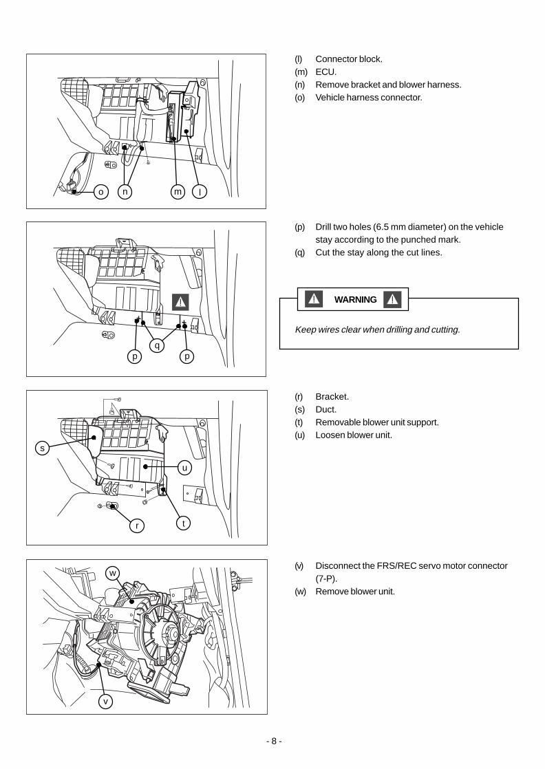
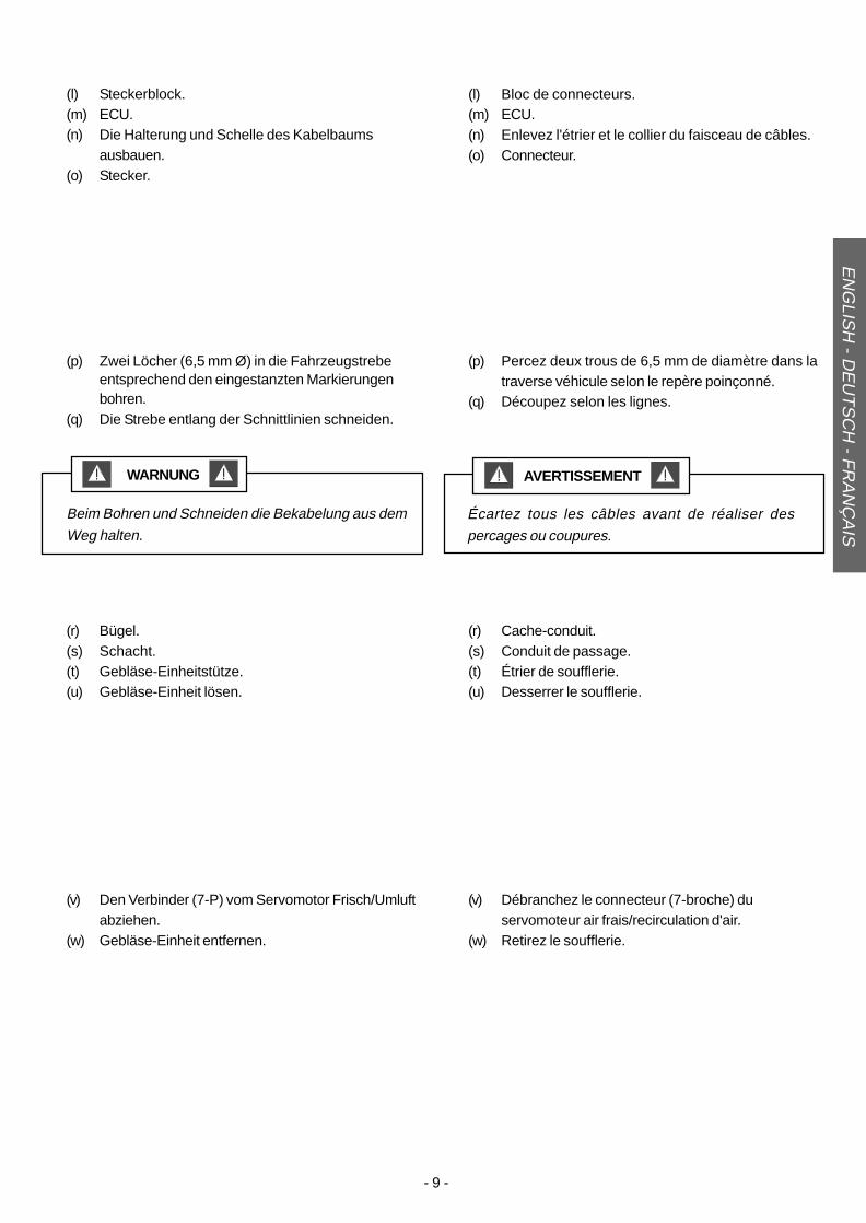
(p) Drill two holes (6.5 mm diameter) on the vehiclestay according to the punched mark.
(q) Cut the stay along the cut lines.
(r) Bracket.(s) Duct.(t) Removable blower unit support.(u) Loosen blower unit.
(l) Connector block.(m) ECU.(n) Remove bracket and blower harness.(o) Vehicle harness connector.
Keep wires clear when drilling and cutting.
WARNING
(v) Disconnect the FRS/REC servo motor connector(7-P).
(w) Remove blower unit.
q
u
s
r t
lmno
pp
v
w
- 9 -
AAUMU-36
(p) Zwei Löcher (6,5 mm Ø) in die Fahrzeugstrebeentsprechend den eingestanzten Markierungenbohren.
(q) Die Strebe entlang der Schnittlinien schneiden.
(p) Percez deux trous de 6,5 mm de diamètre dans latraverse véhicule selon le repère poinçonné.
(q) Découpez selon les lignes.
(r) Bügel.(s) Schacht.(t) Gebläse-Einheitstütze.(u) Gebläse-Einheit lösen.
(r) Cache-conduit.(s) Conduit de passage.(t) Étrier de soufflerie.(u) Desserrer le soufflerie.
(l) Steckerblock.(m) ECU.(n) Die Halterung und Schelle des Kabelbaums
ausbauen.(o) Stecker.
(l) Bloc de connecteurs.(m) ECU.(n) Enlevez l'étrier et le collier du faisceau de câbles.(o) Connecteur.
Beim Bohren und Schneiden die Bekabelung aus dem
Weg halten.
WARNUNG
Écartez tous les câbles avant de réaliser des
percages ou coupures.
AVERTISSEMENT
(v) Den Verbinder (7-P) vom Servomotor Frisch/Umluftabziehen.
(w) Gebläse-Einheit entfernen.
(v) Débranchez le connecteur (7-broche) duservomoteur air frais/recirculation d'air.
(w) Retirez le soufflerie.
EN
GLIS
H - D
EU
TS
CH
- FR
AN
ÇA
IS
- 10 -
AAUMU-36
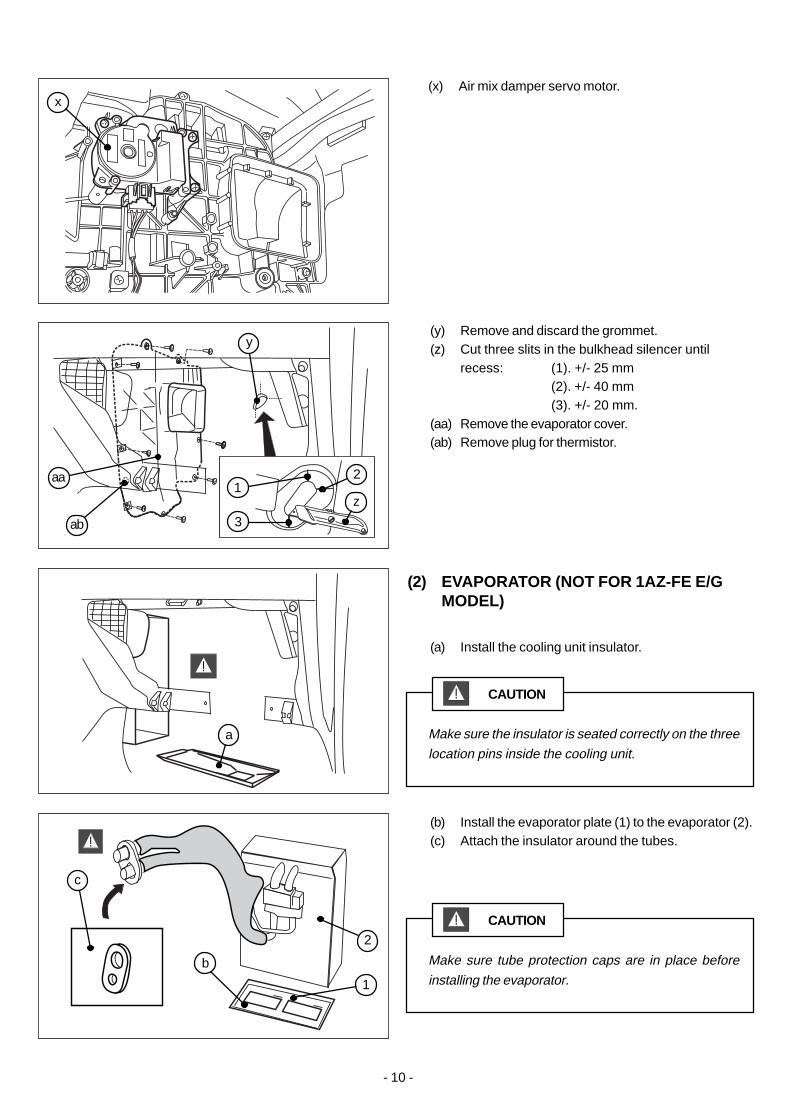
(y) Remove and discard the grommet.(z) Cut three slits in the bulkhead silencer until
recess: (1). +/- 25 mm(2). +/- 40 mm(3). +/- 20 mm.
(aa) Remove the evaporator cover.(ab) Remove plug for thermistor.
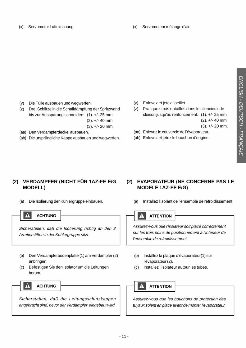
(a) Install the cooling unit insulator.
(b) Install the evaporator plate (1) to the evaporator (2).(c) Attach the insulator around the tubes.
(2) EVAPORATOR (NOT FOR 1AZ-FE E/GMODEL)
(x) Air mix damper servo motor.
Make sure tube protection caps are in place before
installing the evaporator.
CAUTION
Make sure the insulator is seated correctly on the three
location pins inside the cooling unit.
CAUTION
y
2
1
ab
aa
c
a
b
z1
2
3
x
- 11 -
AAUMU-36
(b) Den Verdampferbodenplatte (1) am Verdampfer (2)anbringen.
(c) Befestigen Sie den Isolator um die Leitungenherum.
(b) Installez la plaque d’évaporateur(1) surl’évaporateur (2).
(c) Installez l’isolateur autour les tubes.
(y) Die Tülle ausbauen und wegwerfen.(z) Drei Schlitze in die Schalldämpfung der Spritzwand
bis zur Aussparung schneiden: (1). +/- 25 mm(2). +/- 40 mm(3). +/- 20 mm.
(aa) Den Verdampferdeckel ausbauen.(ab) Die ursprüngliche Kappe ausbauen und wegwerfen.
(a) Die Isolierung der Kühlergruppe einbauen.
(y) Enlevez et jetez l’oeillet.(z) Pratiquez trois entailles dans le silencieux de
cloison jusqu'au renfoncement: (1). +/- 25 mm(2). +/- 40 mm(3). +/- 20 mm.
(aa) Enlevez le couvercle de l’évaporateur.(ab) Enlevez et jetez le bouchon d’origine.
(a) Installez l'isolant de l'ensemble de refroidissement.
(2) VERDAMPFER (NICHT FÜR 1AZ-FE E/GMODELL)
(2) EVAPORATEUR (NE CONCERNE PAS LEMODELE 1AZ-FE E/G)
(x) Servomotor Luftmischung. (x) Servomoteur mélange d'air.
EN
GLIS
H - D
EU
TS
CH
- FR
AN
ÇA
IS
Sicherstellen, daß die Leitungsschutzkappen
angebracht sind, bevor der Verdampfer eingebaut wird.
ACHTUNG
Assurez-vous que les bouchons de protection des
tuyaux soient en place avant de monter l'evaporateur.
ATTENTION
Sicherstellen, daß die Isolierung richtig an den 3
Arretierstiften in der Kühlergruppe sitzt.
ACHTUNG
Assurez-vous que l'isolateur soit placé correctement
sur les trois poins de positionnement à l'intérieur de
l'ensemble de refroidissement.
ATTENTION
- 12 -
AAUMU-36
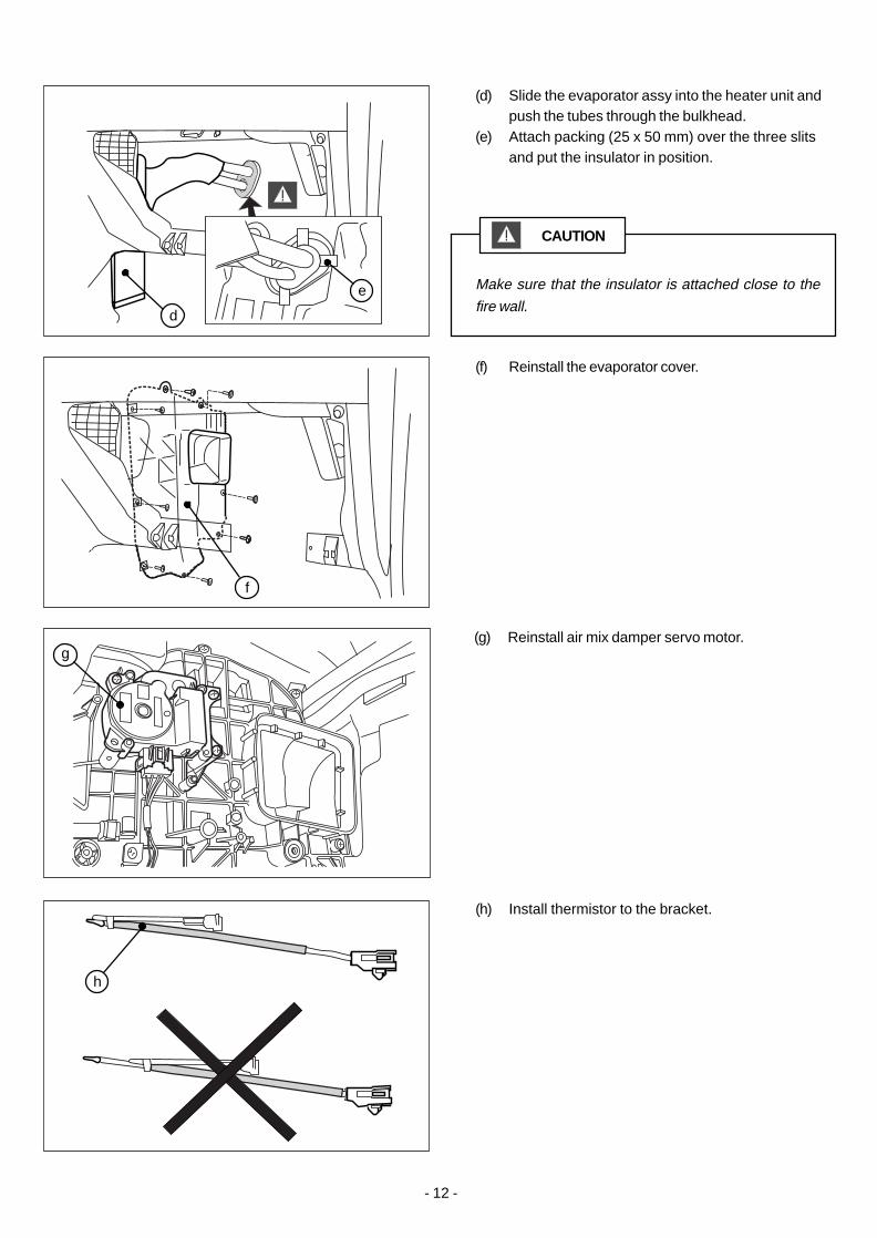
(f) Reinstall the evaporator cover.
(d) Slide the evaporator assy into the heater unit andpush the tubes through the bulkhead.
(e) Attach packing (25 x 50 mm) over the three slitsand put the insulator in position.
(h) Install thermistor to the bracket.
Make sure that the insulator is attached close to the
fire wall.
CAUTION
(g) Reinstall air mix damper servo motor.
d
f
h
e
g

- 13 -
AAUMU-36
EN
GLIS
H - D
EU
TS
CH
- FR
AN
ÇA
IS
(d) Die Verdampferbaugruppe in die Heizungseinheitschieben und die Schläuche durch die Spritzwanddrücken.
(e) Packung (25 x 50 mm) über den drei Schlitzenbefestigen und die Isolierung an ihrem Platzanbringen.
(d) Glissez l’ensemble évaporateur dans le réchauffeuret poussez le tube à travers la paroi.
(e) Fixez le joint (25 x 50 mm) sur les trois entailles etmettez l'isolateur en place.
(f) Den Verdampferdeckel wieder anbringen. (f) Remettez le couvercle de l’évaporateur en place.
(h) Thermistor an der Halterung anbauen. (h) Installez la résistance thermosensible sur l'étrier.
Veiller à ce que l’isolateur soit attaché tout près de la
paroi ignifuge.Sicherstellen, daß die Isolierung nahe an der Spritzwand
angebracht ist.
ACHTUNG ATTENTION
(g) Servomotor Luftmischung wieder einbauen. (g) Remettez en place le servomoteur mélange d'air.
- 14 -
AAUMU-36
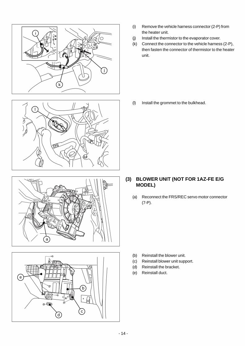
(i) Remove the vehicle harness connector (2-P) fromthe heater unit.
(j) Install the thermistor to the evaporator cover.(k) Connect the connector to the vehicle harness (2-P),
then fasten the connector of thermistor to the heaterunit.
(l) Install the grommet to the bulkhead.
(b) Reinstall the blower unit.(c) Reinstall blower unit support.(d) Reinstall the bracket.(e) Reinstall duct.
(3) BLOWER UNIT (NOT FOR 1AZ-FE E/GMODEL)
(a) Reconnect the FRS/REC servo motor connector(7-P).
k
j
l
a
b
dc
e
i

- 15 -
AAUMU-36
EN
GLIS
H - D
EU
TS
CH
- FR
AN
ÇA
IS
(i) Den Fahrzeug-Kabelbaumverbinder (2-P) von derHeizungseinheit abziehen.
(j) Den Thermistor am Verdampferdeckel anbringen.(k) Erst den Verbinder am Fahrzeug-Kabelbaum (2-P)
anschließen, und dann den Verbinder desThermistors an der Heizungseinheit anbringen.
(i) Déposez le connecteur du faisceau véhicule(2-broches) du réchauffeur.
(j) Fixez le thermistor sur le couvercle del’évaporateur.
(k) Raccordez le connecteur au faisceau véhicule(2-broches), puis fixez le connecteur du thermistorsur le chauffage.
(l) Befestigen Sie den Dichtungsring in derSpritzwand.
(l) Installez le joint dans la cloison.
(b) Die Gebläse-Einheit wieder einbauen.(c) Halter der Gebläse-Einheit wieder einbauen.(d) Den Bügel wieder einbauen.(e) Schacht wieder einbauen.
(b) Remettre la soufflerie en place.(c) Remettre le support de la soufflerie en place.(d) Remettez en place le cache-conduit.(e) Remettez en place le conduit de passage.
(3) GEBLÄSE-EINHEIT (NICHT FÜR 1AZ-FEE/G MODELL)
(3) SOUFFLERIE (NE CONCERNE PAS LEMODELE 1AZ-FE E/G)
(a) Den Verbinder (7-P) vom Servomotor Frisch/Umluftwieder anschließen.
(a) Rebranchez le connecteur (7-broche) duservomoteur air frais/recirculation d'air.

- 16 -
AAUMU-36
(a) Install the A/C amplifier to the blower unit.
(4) A/C AMPLIFIER
(f) Reinstall connector block.(g) Reinstall ECU.(h) Reinstall bracket and blower harness.(i) Reinstall vehicle harness connector.
(b) Connect the vehicle harness (14-P) to the A/Camplifier.
(a) Install the bracket to the vehicle stay using twobolts (black M5 x 12).
(b) Put packing on both bolt thread ends.
(5) BRACKET (NOT FOR 1AZ-FE E/GMODEL)
a
fghi
b
a b
- 17 -
AAUMU-36
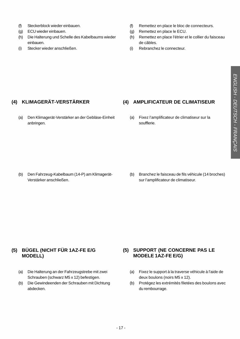
(4) KLIMAGERÄT-VERSTÄRKER
(a) Fixez l’amplificateur de climatiseur sur lasoufflerie.
(a) Den Klimagerät-Verstärker an der Gebläse-Einheitanbringen.
(4) AMPLIFICATEUR DE CLIMATISEUR
EN
GLIS
H - D
EU
TS
CH
- FR
AN
ÇA
IS
(f) Steckerblock wieder einbauen.(g) ECU wieder einbauen.(h) Die Halterung und Schelle des Kabelbaums wieder
einbauen.(i) Stecker wieder anschließen.
(f) Remettez en place le bloc de connecteurs.(g) Remettez en place le ECU.(h) Remettez en place l'étrier et le collier du faisceau
de câbles.(i) Rebranchez le connecteur.
(b) Den Fahrzeug-Kabelbaum (14-P) am Klimagerät-Verstärker anschließen.
(b) Branchez le faisceau de fils véhicule (14 broches)sur l’amplificateur de climatiseur.
(a) Die Halterung an der Fahrzeugstrebe mit zweiSchrauben (schwarz M5 x 12) befestigen.
(b) Die Gewindeenden der Schrauben mit Dichtungabdecken.
(a) Fixez le support à la traverse véhicule à l'aide dedeux boulons (noirs M5 x 12).
(b) Protégez les extrémités filetées des boulons avecdu rembourrage.
(5) BÜGEL (NICHT FÜR 1AZ-FE E/GMODELL)
(5) SUPPORT (NE CONCERNE PAS LEMODELE 1AZ-FE E/G)
- 18 -
AAUMU-36
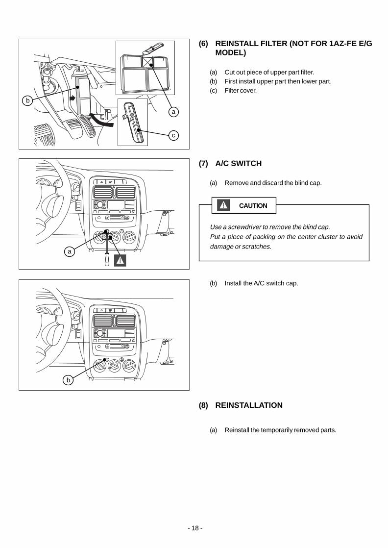
(a) Cut out piece of upper part filter.(b) First install upper part then lower part.(c) Filter cover.
(a) Remove and discard the blind cap.
(a) Reinstall the temporarily removed parts.
(6) REINSTALL FILTER (NOT FOR 1AZ-FE E/GMODEL)
(7) A/C SWITCH
(8) REINSTALLATION
Use a screwdriver to remove the blind cap.
Put a piece of packing on the center cluster to avoid
damage or scratches.
CAUTION
(b) Install the A/C switch cap.
160
120
2
34
H
C
160
120
2
34
H
C
A/C
c
a
b
a
b

- 19 -
AAUMU-36
EN
GLIS
H - D
EU
TS
CH
- FR
AN
ÇA
IS
(a) Oberes Teil des Filters herausschneiden.(b) Erst das obere Teil dann das untere Teil einbauen.(c) Filterdeckel.
(a) Die ursprüngliche Kappe ausbauen und wegwerfen.
(a) Die provisorisch ausgebauten Teile wiedereinbauen.
(a) Découpez un morceau de la partie supérieure dufiltre.
(b) Installez tout d'abord la partie supérieure puis lapartie inférieure.
(c) Couvercle du filtre.
(a) Enlevez et jetez le bouchon d’origine.
(a) Remettre en place les pièces enlevéestemporairement.
(6) FILTER WIEDER EINBAUEN (NICHT FÜR1AZ-FE E/G MODELL)
(6) REMISE EN PLACE DU FILTRE (NECONCERNE PAS LE MODELE 1AZ-FE E/G)
(7) KLIMAGERÄT-SCHALTER (7) COMMUTATEUR DE CLIMATISEUR
(8) WIEDEREINBAU (8) REINSTALLATION
Mit einem Schraubendreher die ursprüngliche Kappe
entfernen. Eine Dichtung über das mittlere
Instrumentenfeld kleben, damit es nicht beschädigt oder
zerkratzt wird.
ACHTUNG
Enlevez le bouchon d'origine à l'aide d'un tournevis.
Protégez le panneau central des rayures ou des
coupures avec du rembourrage.
ATTENTION
(b) Die Kappe des Klimaanlagenschalters einbauen. (b) Montez le bouchon du commutateur de climatiseur.

- 20 -
AAUMU-36

AAUMU-36
© 2000 (EUROPE) B.V..
SERVICE DEPARTMENT
WEESP, THE NETHERLANDS
FIRST ISSUE: JULY 2000
PUBLICATION NO.: AAUMU-36
AAUMU-36
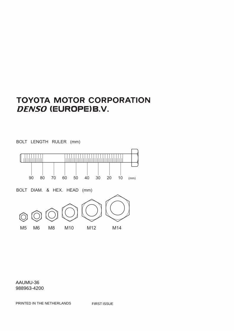
BOLT LENGTH RULER (mm)
BOLT DIAM. & HEX. HEAD (mm)
(mm)20 1030405060708090
M14M12M10M8M6M5
PRINTED IN THE NETHERLANDS FIRST ISSUE
AAUMU-36988963-4200